
Timeline

Since I no longer had to create a physical table, my timeline for this project became more relaxed. I was able to step away from the project for the duration of Spring Break and was able to dedicate two full weeks to modeling my table on Rhino 6. I spent the following week creating digital renderings on Autodesk Fusion 360 and spent the last three days before the beginning of our presentations completing the documentation and building my power point. If I find additional things to adjust based on my presentation, I will take care of them before the Zoom Showcase on May 3rd.
Rhino 6
A few semesters ago I learned how to create 3D models on Rhino 6. Thanks to this skill, I was able to modify my plans for my folding coffee table in light of the pandemic and created a 3D model of it instead.
To begin, I created the oval, wooden table top and added dimension marks. The table itself is quite large (24″ X 48”) because I wanted it to meet my requirement of being able to fit at least four people comfortably. The additional dimensions are for the hinges that will hold the copper tube legs. The spaces are staggered to allow the legs on either half to cross each other without clashing.

Initially, I had not considered that the legs themselves would need slots within the bottom of the table so that they sit flushed when the table is put a way. Only after I created an iteration of the table closed, I carved rails for them to sit. Later, when I added the thumbscrews, I carved the piece of wood once again to give them a space.

Next, I created the legs. I did not know how much material I would need but I did know how tall I wanted the table to be at its highest point (34”). 
In order to “attach” the legs to the table top, I needed hinges. McMaster-Carr helped me find an adjustable angle elbow hinge which I modified in my document to have a flat side. This may not necessarily be an appropriate way of customizing a hinge but it was the best 3D model I could find.
 Aluminum Slip-on Fitting, Adjustable-Angle Elbow Connector for 1-1/4” Rail OD [1]


Additionally, I borrowed 3D models of a wing nut and a thumb screw to show functionality. By tightening and loosening these two components, one can adjust the height of the table.
 Wing Nut Steel, 5/16″-18 Thread Size, 15/32″ Base Diameter [2]
 Stainless Steel Knurled-Head Extended-Tip Thumb Screw 5/16″-18 Thread Size, 2-3/4″ Long [3]


Room for Improvement

At the foot of the table, I originally sliced off the tubes when they touched the bottom. The problem came when I tried to re-adjust the height of the table to an in-between setting. Unless the table is at maximum height or closed, the feet do not adjust themselves to the floor, making them unable to balance and prone to scratching the surface below. For the future, I plan to add metal base swivel attachments like the one below.
 Metal Base Swivel Glide [4]
 Swivel Leveling Mount Corrosion-Resistant with 32 mm Long M8 Threaded Stud [5]
Autodesk Fusion 360
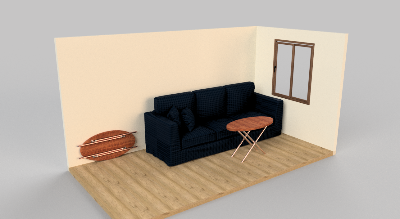
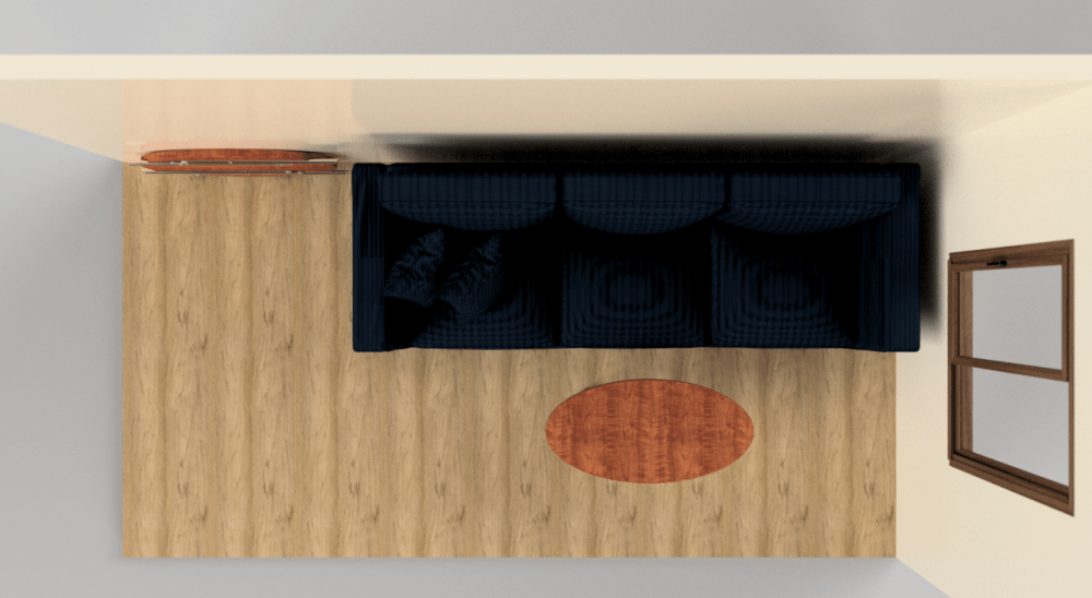
After creating the table and building an environment for it in Rhino 6, I imported the document into Autodesk Fusion 360 where I added colors and textures to all of the elements and rendered them. The renders show the table as it would look in front of a couch and leaning against a wall. When the table is closed, it can fit nicely behind a couch or lay nonchalantly to the side. Whether open or closed, it does not take up too much space. I purposely did not include many ornaments in the room to show that the table does not need embellishments or an excessively decorated environment to be beautiful.


Looking Ahead
At the end of the day, I am glad that I spent all of this time creating a 3D model rather than the actual table. Ideally, the final product is something that I want to be proud of and keep for a long time. It is something that I want to dedicate myself to and do it right. Originally, I was not planning on creating a digital version whatsoever of the table. The plan was to create several sketches, buy my materials, and get to it. Had I proceeded that way, I would not have realized that I needed to carve wells into the wood for the legs, or that I needed swivel bases for the legs. I am sure that even tough I examined most details while making the 3D model, I still overlooked other minor details that I simply could not possibly be aware of unless I were working with real materials. Nevertheless, I learned how to properly conceptualize my designs and feel less intimidated by working with the physical objects.
I look forward to the upcoming Summer months to bring my design to life in a post-quarantine time. Now that I have focused mainly on the aesthetic, I will focus on functionality. I will make sure that the table will hold as much weight as I would like it to, I will experiment with different thumb screws to see which ones feel better to use, I will look into different hinges and examine how they can be attached to the table without damaging the wood. I will use all of my resources to learn more about wood working and finally create a coffee table for my apartment!
Presentation Video
Sources
[1] https://www.mcmaster.com/4698t83[2] https://www.mcmaster.com/90876a355
[3] https://www.mcmaster.com/93015a222
[4] https://tinyurl.com/y9wnaxzy
[5] https://www.mcmaster.com/6301k87
1 Comment. Leave new
Hey Nicole! It’s great to hear that you are continuing with this project, as I’m sure the final product will look great. As a statement of meaning, I enjoyed your room for improvement section. It was great to see you were looking ahead. As a neutral question, does what you learned about the design phase of a project over this semester change the way you plan to tackle projects in the future? In other words, do you plan on spending more time sketching things out before actually working on the hardware? As a permissioned opinion, I would look into creating some engineering drawings for these parts prior to construction. This would help you greatly during the fabrication and assembly process.