
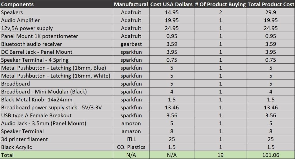
Starting out with the cost of the project as seen in Table 1, the total price to complete this project came out to be a little over $160 dollar. My budget that I set out for this project was $150 dollar, but one thing to take into consideration is that I did not use all of the 3D filament or black acrylic. I would say that if I was to just by the filament I needed for the 3D printer it would be a maximum of 5 dollars, this would bring the cost down to $141.06 dollars putting me in the budget rage that I set my self. In the table below you will see the components, the amount of each product, and the cost per unit.
Path to build your own Bluetooth speaker
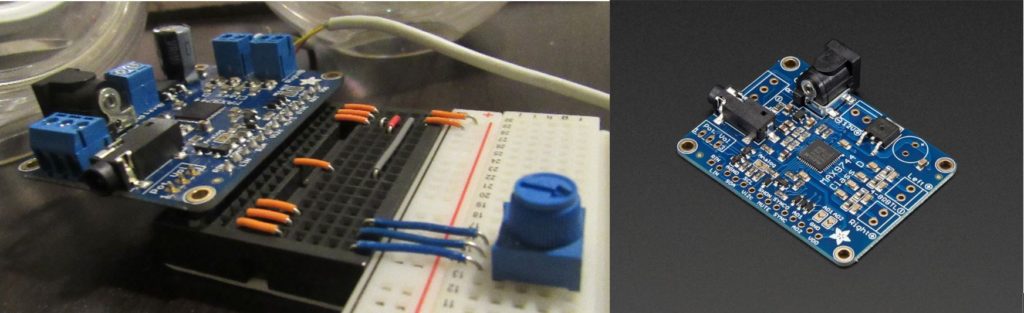
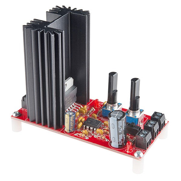
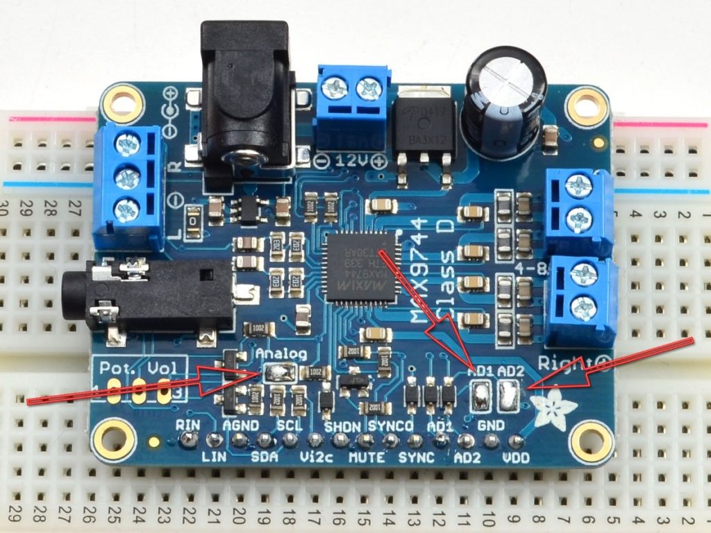
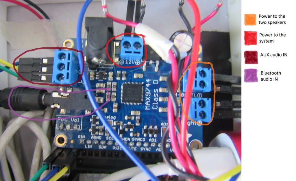
For my final project I created Bluetooth speakers and designing the overall exterior look for both the electronics box and the two speakers. For the brains of my project I used a high-efficiency class D audio amplifier as seen in Figure 1. The Amplifier provide most of the functionality that the system as a hole, such as volume control, 20 Watts of power to each speaker and 5v of power to the white LED, as well as providing two ports for audio in as seen in Figure 3. The way that I started building this concept of Bluetooth stereo system was by doing research on audio amplifiers for power, functionality, ease of use, and flexibility (meaning that I could change functions). There was two that I had set my heart in, one being SparkFun Audio Amplifier that would put out 30 Watts of power and already had analog volume control seen in Figure 2, and of course the other being the Adafruit Class D audio amplifier in Figure 1. The reason that I went with the Adafruit over the SparkFun was because it was smaller and it provided flexibility (in terms that if I wanted to I could make the volume controls both analog and/or digital).
Building and prototyping
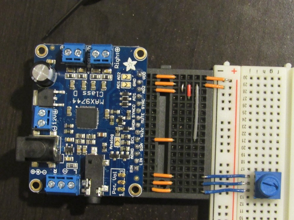
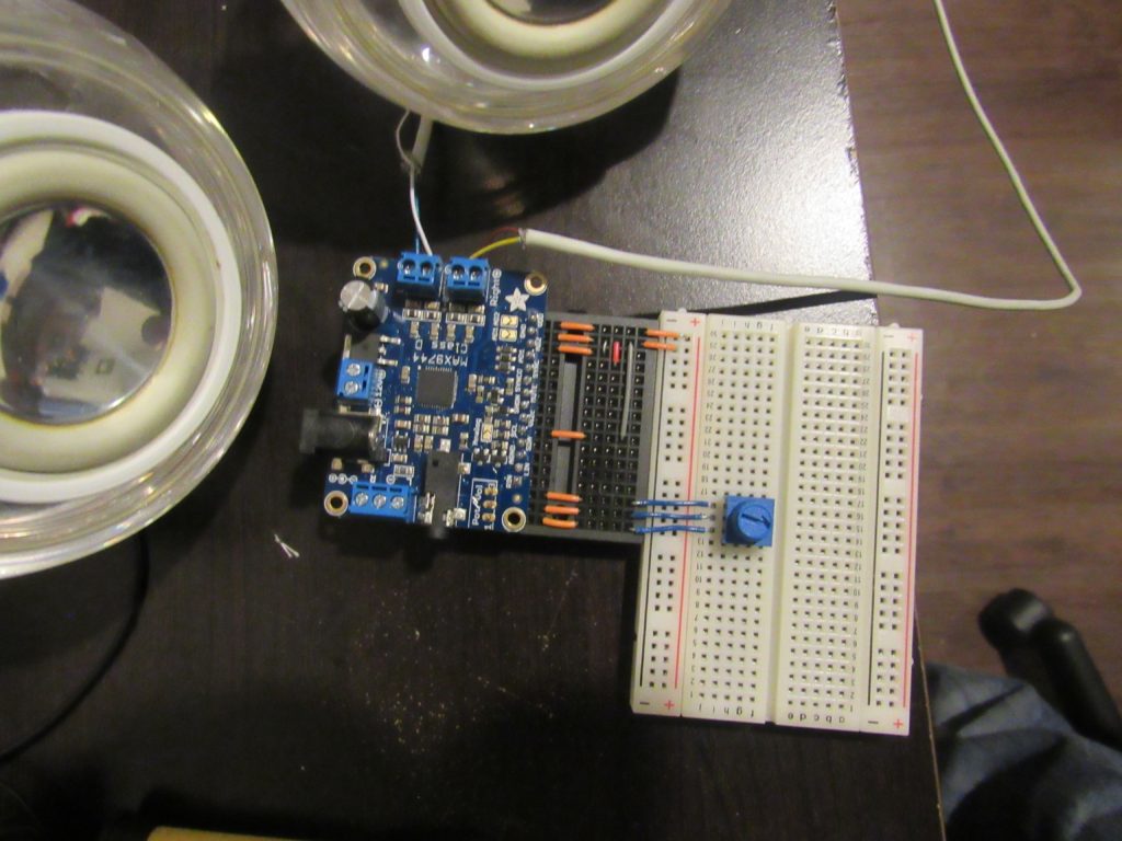
Once I knew the amplifier that I was going to use the rest was a little more strait forward of how the system will function. I wanted to have analog volume control because it gives it a more natural look and feeling to the hole experience, but the amplifier default setting wore digital and so I rewired a few outputs and inputs to the amplifier pins as instructed on the back seen in Figure 4. There are Two ways of making the audio amplifier analog, one is to close the three jumper labeled Analog, AD1, AD2 as you can see in Figure 5. The second is to get jumper wires and connect SCL/ AD1/AD2 pins on the amplifier to ground as seen in Figure 4 and Figure 6. Once you have converted it to analog you can then connect a 1k potentiometer to the three Pot. Volume. I ended up doing the second options in the case that I wanted to make it digital later on in the semester as you can see in Figure 6.

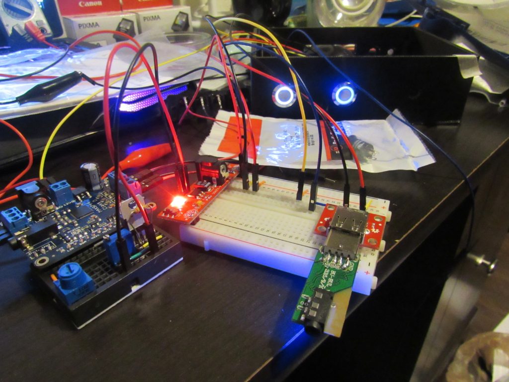
I always want to check that my electronics are working properly early on, and I would say that it is a good rule of thumb to do so. So I assembled the amplifier so it had power and the speakers wore connected to check the audio control and that sound was actually coming out of the speakers. You can see the setup in the Figure 7.
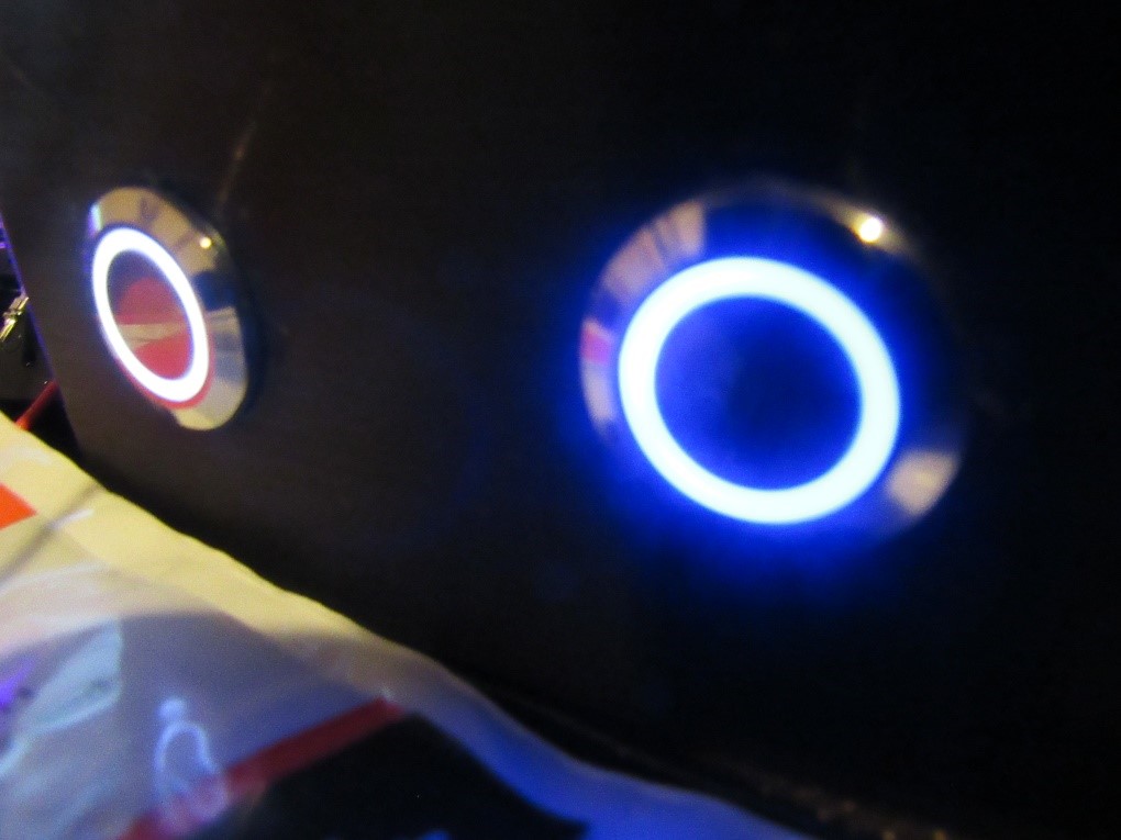
Now that I had a working audio amplifier it was time to improve on it and make it more functional and actually add some aesthetics. I wanted the amplifier to also have an on/ off bottom rather than plugging the power cord in and out to turn it on and off. Because the amplifier had two ports for audio IN, one was reserved for AUX and the other for Bluetooth. I also wanted to have Bluetooth capabilities and the option of having Bluetooth to also be turned on/off, so I added a button to turn it on/off as well. Finally, I wanted to know when my devise was on/off for both the amplifier and the Bluetooth but I did not want to add to much stuff seeing that for this project less seemed to be more, that’s why I searched for a button that had LED already implemented in it. The buttons turned out great, they wore very bright that I could see them even during daylight you can see in Figure 8.
Once I had all the components working individually I went on to put them together. In my research in finding the audio amplifier I found that this one had a 12-volt output on the VDD pin that I could use to power the Bluetooth and the LEDs, but I ran into two problems one was that the LEDs and the Bluetooth receiver ran at 5 Volts not 12 Volts. The second was that once I got the voltage down to 5 volts using a voltage regulator, aside from the LEDs working great the Bluetooth receiver gained some static and distorted the sound when the volume was lowered in Figure 9 you can see the first few attempts. I tried everything that I could think off to try to fix it but eventually I decided to power the Bluetooth separately using a power bank I got from BestBuy for 7 or 10 dollars.
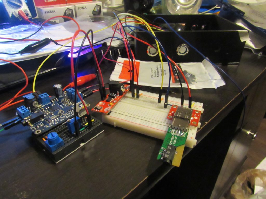
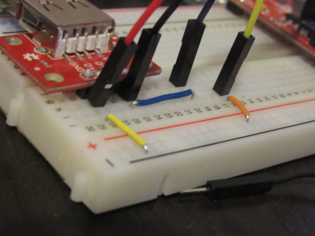
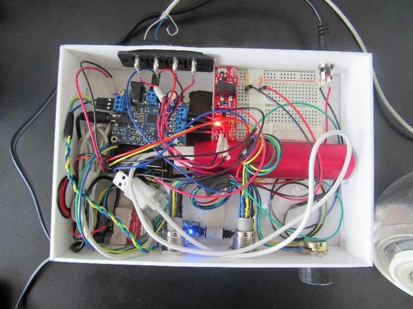
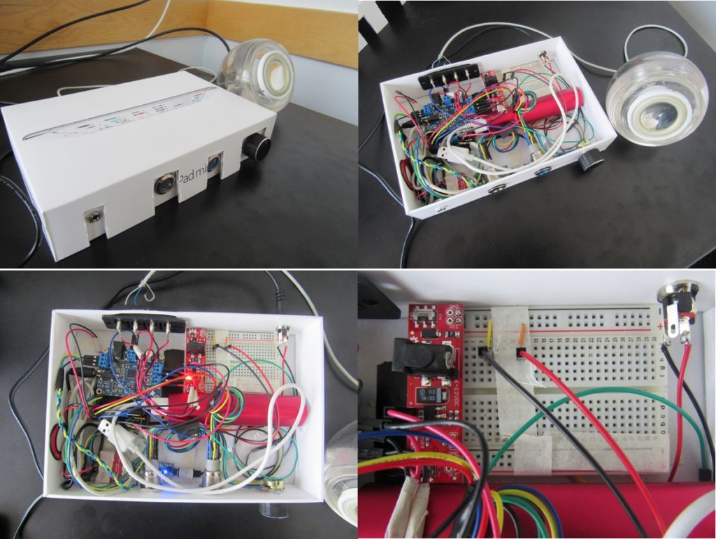
In the attempt to get the Bluetooth to work as I intended, I obtained a box that would represent a similar size of what the final product would look. In Figure 10, you see one of the final prototypes, I used an IPad mini box that was able to house all of the components connected to the audio amplifier including the power bank and the audio Bluetooth receiver, in Figure 11 you can see a closer look of how every thin was connected. The speaker that you see in the pictures was to test my system and due to its durability and size to be able carry them around. The speakers are from an old Mac computer were the audio plug was out of date and would not fit in any audio jack. Once I got everything to fit in the box I went on to use SolidWorks (a 3D modeling software) to design the box that would house all off the electronics, as well as making the speaker housing to amplify the sound and give them some aesthetic look to match the electronic box.
Bellow is a recap of all the components that wore placed in the final prototype.
This video will explain and show how everything works.
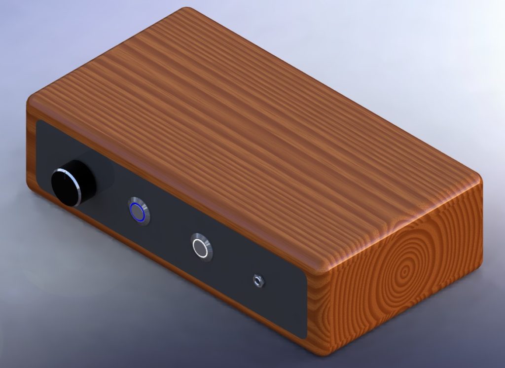
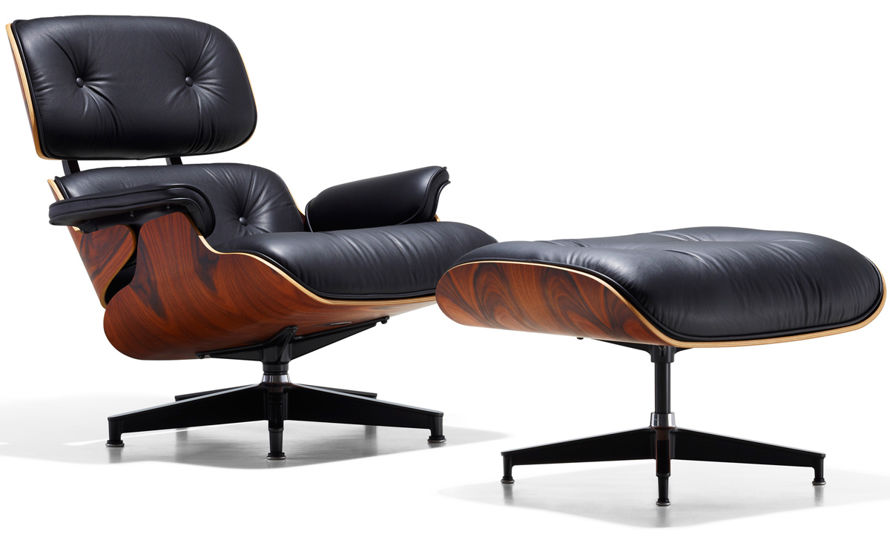
The inner dimensions of the box wore the most important 5 X 8 X 1.3 inches was the min dimensions that I set to allow the electronics to fit properly. Aside from the interior volume restriction that I set as a precaution, I then went on to create a few designs. In Figure 12 you see one of my first designs, this design was inspired by the Eames Lounge Chair shown in Figure 13. I really liked how this high quality chair looked, and it was not just the quality of the material but how they complimented one another. The black leather with the dark stain really sold me to making my first design on SolidWorks. What you are seeing in Figure 12 I a dark stain wood exterior with a glossy black acrylic on the front and back. This provided a very slick look to the overall design and I felt that these two materials worked very well in complimenting one another. The intent was to make a design that made the user feel that he or she had a high quality, and well-made product. Unfortunately, some of the geometry turned out to be too complex for the material I had available at home. Although the design was doable if I used a CNC machine, the problem in completing this design was that you needed at least two-week notice to complete the code conversion from SolidWorks to the CNC program. Due to time I when back to the drawing board, and looked at all the resources that I had to complete the project on schedule.
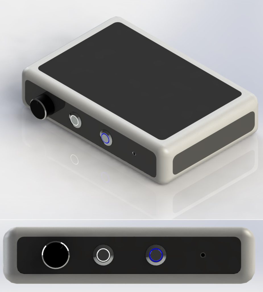
After looking over my options and the time I had left I decided to exchange the wood for a silver 3D printable filament. The new design had its pros and cons when it came to manufacturing. I had to take into account how long it would take me to print it. The other concern was the size that it had to be to hold all of the electronics, for that reason I became more restricted of whish 3D printers I could use limiting me to the larger Taz 5 that are available in the ITLL. The pros of doing 3D printed parts are that you can make them very complex, although it takes a lot of time you can walk away and do other stuff as it is being printed, and it fit with my time restrictions. For the design that you see in Figure 14 was carefully design to still look as a high end product and reduce the amount of time needed to complete it. As you can see in the picture below there is a lot more black acrylic in Figure 14 then there is in Figure 12. There are two main reasons I implemented that design, one was to give a more polish and sophisticated look to the design, and the other was to reduce the parts needed to be printed and the time it took to complete the task. Once the silver casing was completed I premeasured all of the cut out to make sure the black acrylic fit perfectly and once the measurements wore updated the acrylic cut using a laser cuter. I was very happy how it turned out, and the I was able to reduce the profile significantly because the wall thickness was set to 1/8 inch in comparison to the wood design. Seen in Figure 12 the wood design has a wall thickness of 3/4 inch that made to overall look bulky.
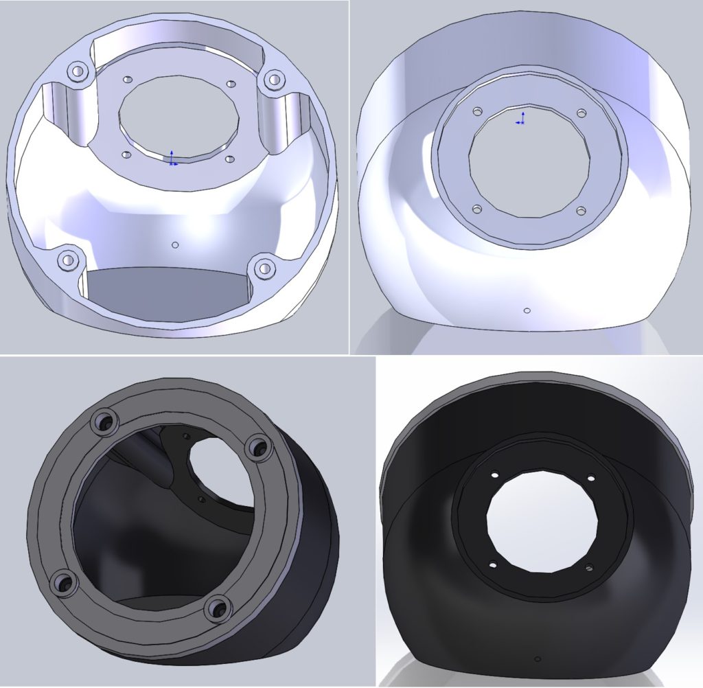
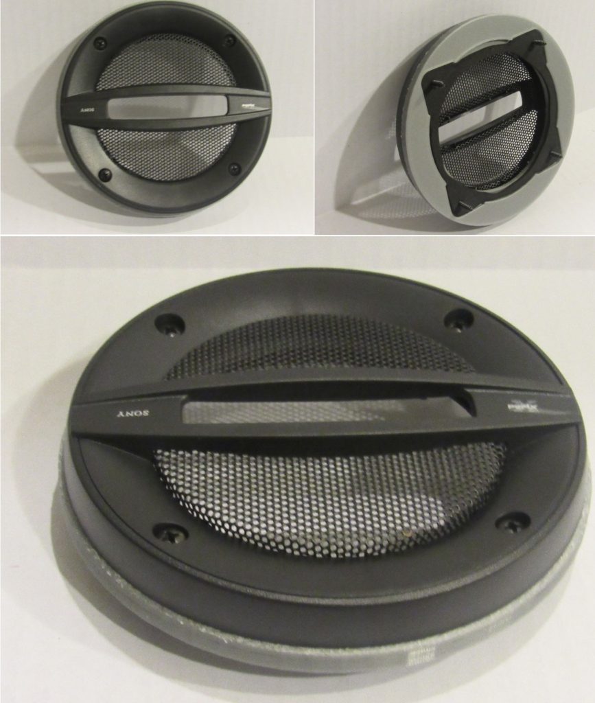
Once the amplifier box was fully assembled it could provide high quality sound with any speaker you plugged in it. I wanted the aesthetic to stay uniformed, from the speakers to the amplifier system. The next step was to creating the casing for the speaker, because I was already using 3D printing to make the amplifier and electronics box I decide to also 3D print the speaker casings as well. In Figure 15 are my first and last design because they worked and all the parts fit together nicely. What I made sure that I included into this design was for the speaker to be angled to face me if I was sitting down on my desk, this was in the intent to direct the sound directly to me. The other part was having the extrusion to fit screws to mount the speaker, and finally I made a section on the back to fit a more aesthetically pleasing wire connection for power.
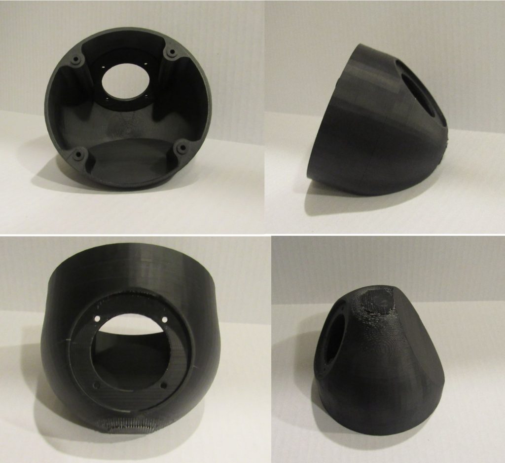
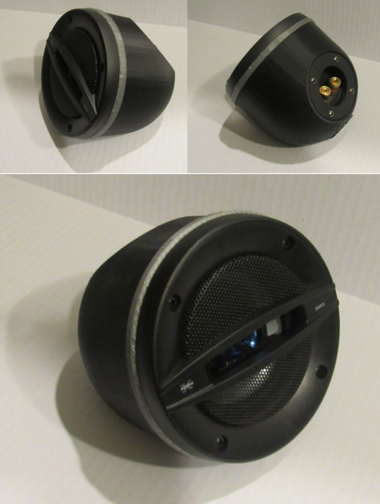
The 3D printed parts came out very nice and they fit well with each other. Interestingly enough I did use two different types of materials when I 3D printed them, this is important because depending on the material you are able to do some additional post processing to make them look smoother. The part in Figure 16 was printed with ABS, the intent for this choose was that you could apply acetone to it and make the surface smooth and also get rid of the layer that propagate when you use a 3D printer. This also provided a more of a glossy look that would match the black acrylic. The other material that was used is PLA, this material already prints out with a glossy finish but there is not a lot of post processing that you can do like the ABS. Each material has their pros and cons there it is the ease of post processing like the ABS or the higher strength of the PLA. The finished 3D printed parts are shown In Figures 16 and 17.
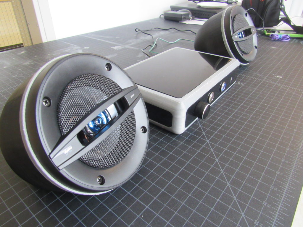
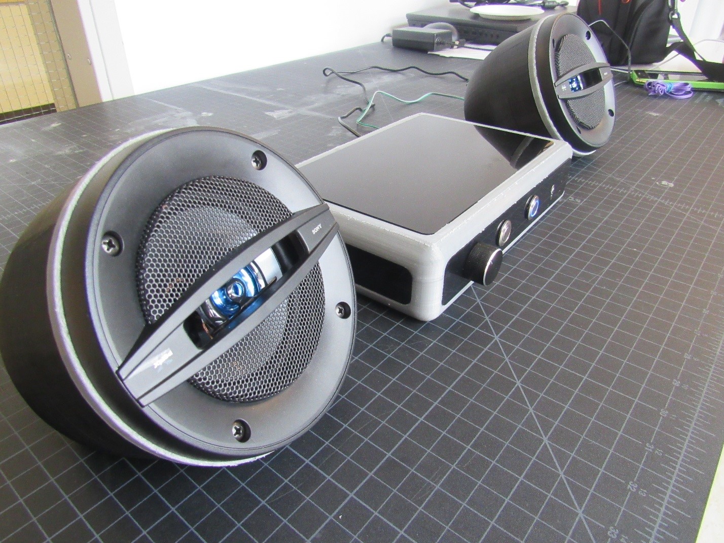
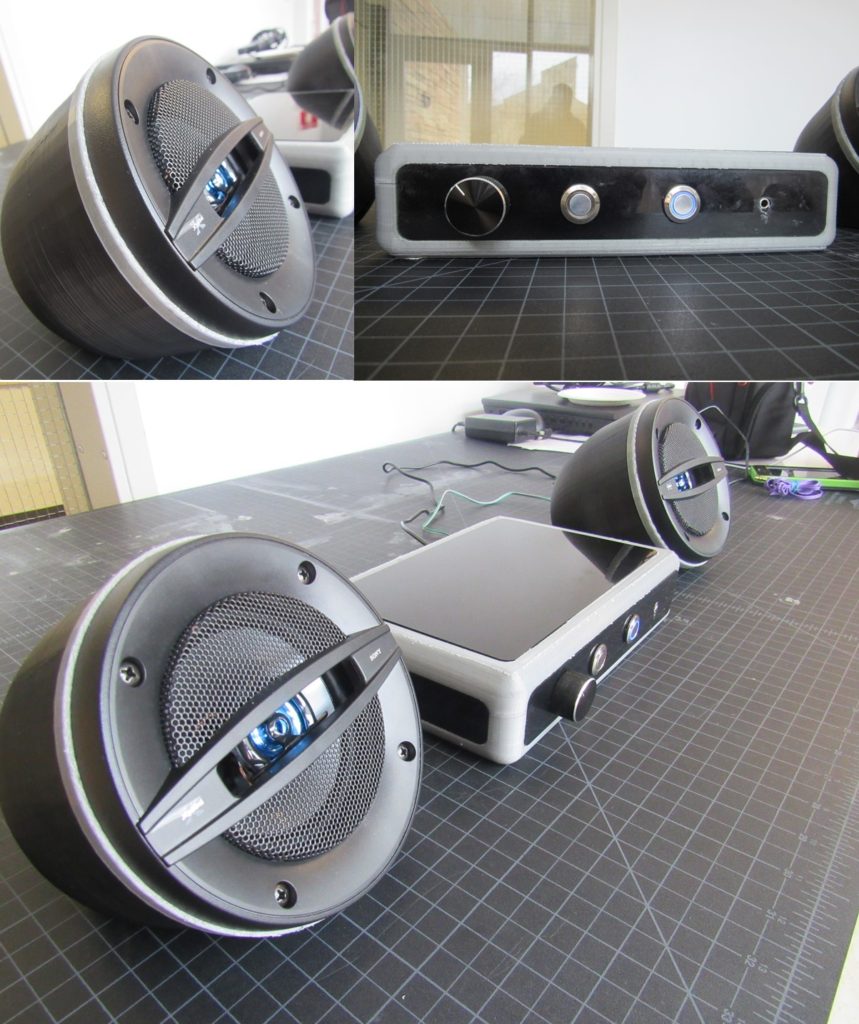
In Figure 18 shows the final assembly of the speaker casing. I really liked how the speakers turned out. In Figure 19 you can see the entire system completed. Over all this was a very fun project from start to finish, and know I have my very own blue tooth system. Moving forward with this project I like to coat the ABS material with acetone to give it that nice glossy look, but overall I am very happy how this turned out.
Although I did not end up implementing the hologram I feel that the project went in a good direction. I do think that I had enough time to apply the hologram to my system, but mid-way through the semester I feel that it would hurt my end design more than add to it. Once I dropped the hologram idea I had more time to really focus on the needy details that made the project stand out. The reaction that I got from people in the expo was what I hoped for, they really liked the functionality of the product together. Interesting enough I got more amassment on the speakers overall look more then the other parts and commented on a well-polished project.
One things I would probably change of this project if I wore to do it again is perhaps make it out of a nice stained wood. Even though most parts wore 3D printed the project turned out looking very nice, and so I believe will just keep this design as it is.
There are many reasons why I would recommend this project to others, but the reason I decided to do it was to learn more about electronics and amplifiers. I also wanted to do a project that at the end of the semester I could enjoy. I will say that I am really happy how it turned out and I will be using it at my graduation party, and at home.
2 Comments. Leave new
My father is a hardcore speaker player, your speaker is great too
This is an amazing device! Also, the blog is very detailed, so I think I can build my own now variant too. The final design is super sleek, and you put a lot of hard work into making the electronics run smoothly. I remembered we talked a little about the challenges of 3-D printing the box, but overall it ended up looking great!