Home
Most Recent (2026)
Past Work
Light fixture
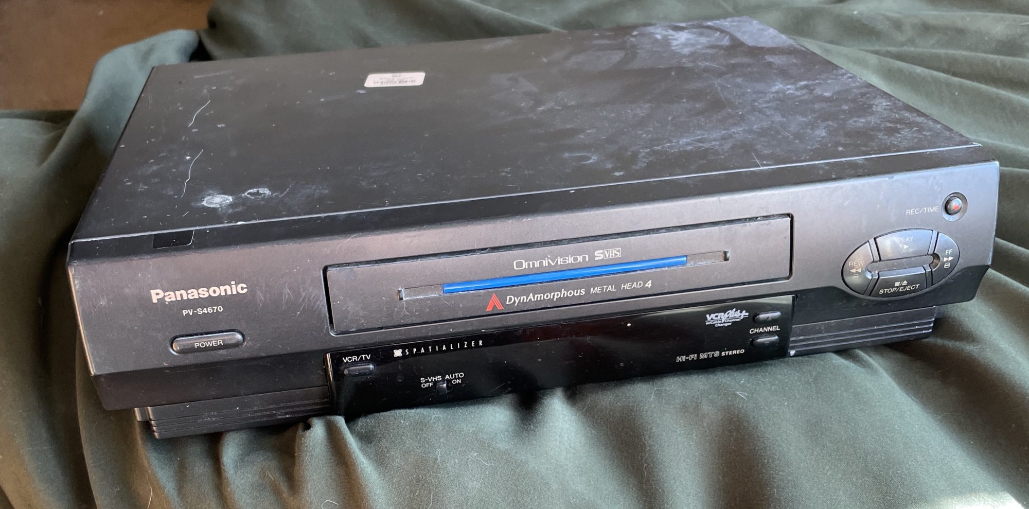
A/V music tech
Furniture
Mirror
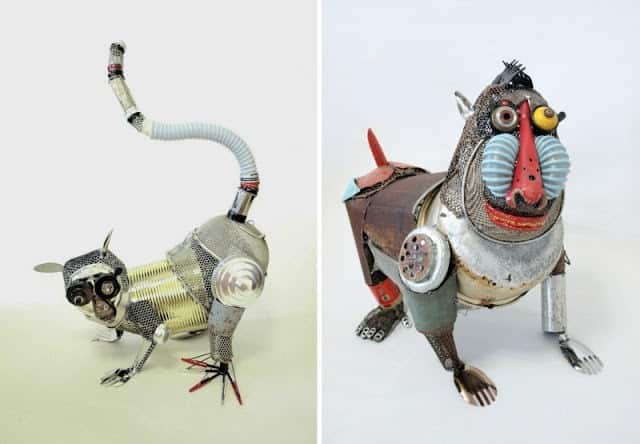
Pet Accessory
Product Design
Sculpture
Wall art
Other
2025
Post 01 2025: Aesthetic Explorations
Post 2- 2025 : What is your Upcycling project? What is the aesthetic and why?
Post 3 – 2025 : Upcycle Progress
Post 4- 2025 : Opposite Upcycle Aesthetic
Post 5 – 2025: Upcycle Design Report
Post 6 – 2025 : Main Project Plans and Inspirations
Post 7 – 2025 : Main Project Aesthetics: Plans and Alternatives.
Post 8 – 2025 : Design Preview Report
Post 9 – 2025 : Top 5 specifications, top 5 constraints
Post 10 – 2025 : Progress
Post 11 – 2025 : Final Report Part 1
Post 12 – 2025 : Main Project Final Report Part 2
Post 13 – 2025 : Portfolio
2024
Post 1: Aesthetics Exploration
Post 2: What is your upcycling aesthetic and why?
Post 3: Upcycle progress
Post 4: Opposite Upcycle Aesthetic
Post 5: Upcycle Design Report
Post 6: Main project plans and inspiration
Post 7 2024: Main Project Aesthetics – Plans and Alternatives
Post 8 2024: Design Preview Report
Post 9 2024: : Top 5 specifications, top 5 constraints
Post 10 2024: Progress Since Design Preview
Post 11 2024 Final Report Part 1: What and Why
Post 12 2024: How and What Next?
Post 13 2024: Portfolio
2023
Post 1 – 2023
Post 2 – 2023
Post 3 – 2023
Post 4 – 2023
Post 5 – 2023
Post 6 – 2023
Post 7 – 2023
Post 8 – 2023
Post 9 – 2023
Post 10 – 2023
Post 11 – 2023
Post 12 – 2023
Post 13 – 2023
2022
Post 1 – 2022
Post 2 – 2022
Post 3 – 2022
Post 4 – 2022
Post 5 – 2022
Post 6 – 2022
Post 7 – 2022
Post 8 – 2022
Post 9 – 2022
Post 10 – 2022
Post 11 – 2022
Post 12 – 2022
Post 13 – 2022
2021
Post 1 – 2021
Post 2 – 2021
Post 3 – 2021
Post 4 – 2021
Post 5 – 2021
Post 6 – 2021
Post 7 – 2021
Post 8 – 2021
Post 9 – 2021
Post 10 – 2021
Post 11 – 2021
Post 12 – 2021
Post 13 – 2021
2020
Post 1 – 2020
Post 2 – 2020
Post 3 – 2020
Post 4 – 2020
Post 5 – 2020
Post 6 – 2020
Post 7 – 2020
Post 8 – 2020
Post 9 – 2020
Post 10 – 2020
Post 11 – 2020
Post 12 – 2020
Post 13 – 2020
2019
Post 1 – 2019
Post 2 – 2019
Post 3 – 2019
Post 4 – 2019
Post 5 – 2019
Post 6 – 2019
Post 7 – 2019
Post 8 – 2019
Post 9 – 2019
Post 10 – 2019
Post 11 – 2019
Post 12 – 2019
Post 13 – 2019
2018
Post 1 – 2018
Post 2 – 2018
Post 3 – 2018
Post 4 – 2018
Post 5 – 2018
Post 6 – 2018
Post 7 – 2018
Post 8 – 2018
Post 9 – 2018
Post 10 – 2018
Post 11 – 2018
Post 12 – 2018
Post 13 – 2018
2017
Post 1 – 2017
Post 2 – 2017
Post 3 – 2017
Post 4 – 2017
Post 5 – 2017
Post 6 – 2017
Post 7 – 2017
Post 8 – 2017
Post 9 – 2017
Post 10 – 2017
Post 11 – 2017
Post 12 – 2017
Post 13 – 2017
2016
Post 1 – 2016
Post 2 – 2016
Post 3 – 2016
Post 4 – 2016
Post 5 – 2016
Post 6 – 2016
Post 7 – 2016
Post 8 – 2016
Post 9 – 2016
Post 10 – 2016
Post 11 – 2016
Post 12 – 2016
Post 13 – 2016
Resources
Blog and Blog Comment/Critique Policies
Presentation Critiques
Pod and Critique Facilitator Responsibilities
Sources for materials
Student Resources
Zotero Library Access
Designers and fun links
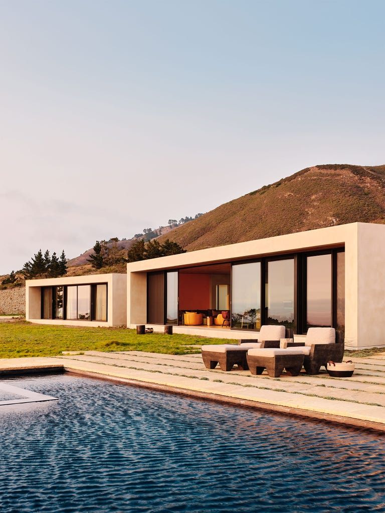
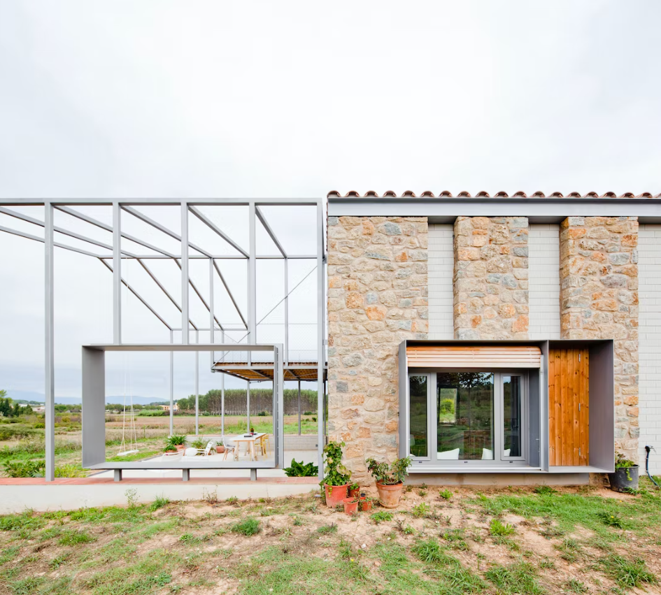
Aesthetic Exploration – Modern Architecture, Jakubczak
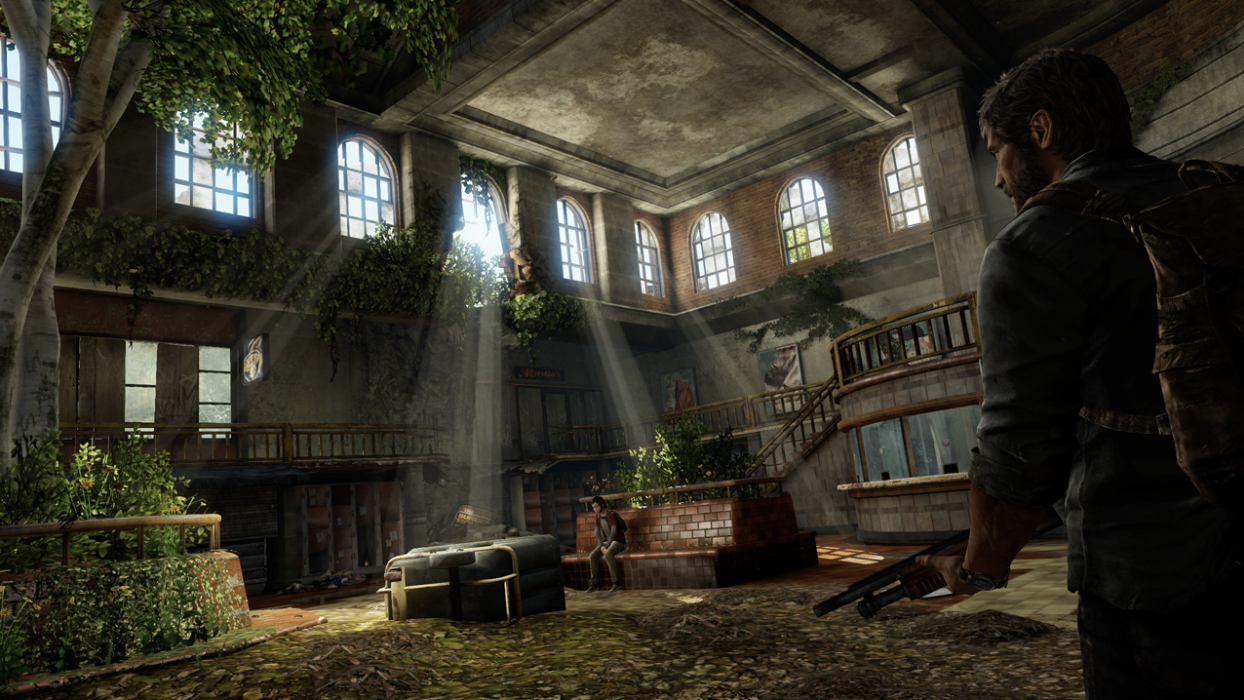
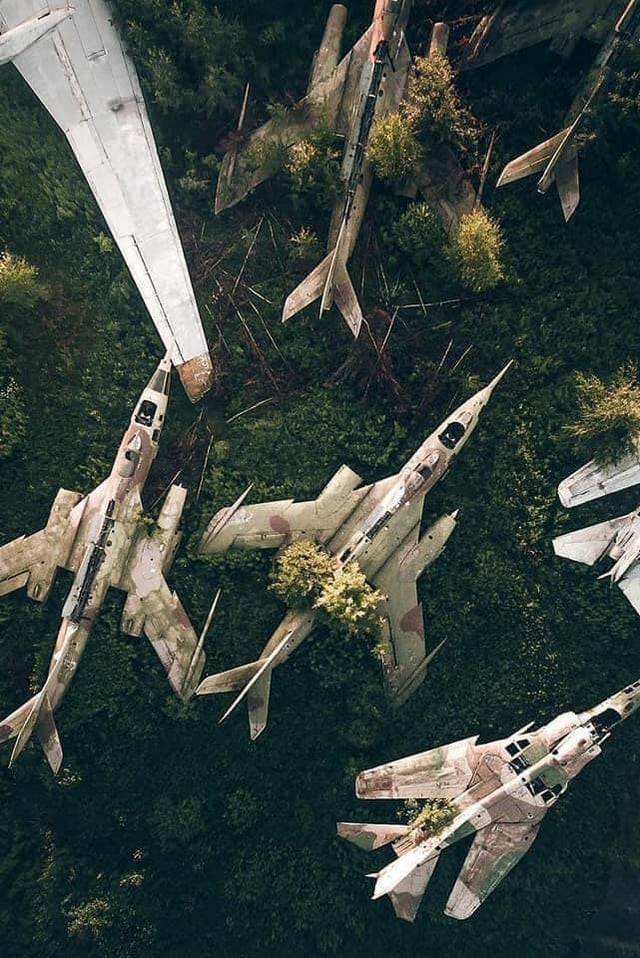
Aesthetic Exploration – Nature Reclaiming Civilization
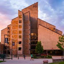
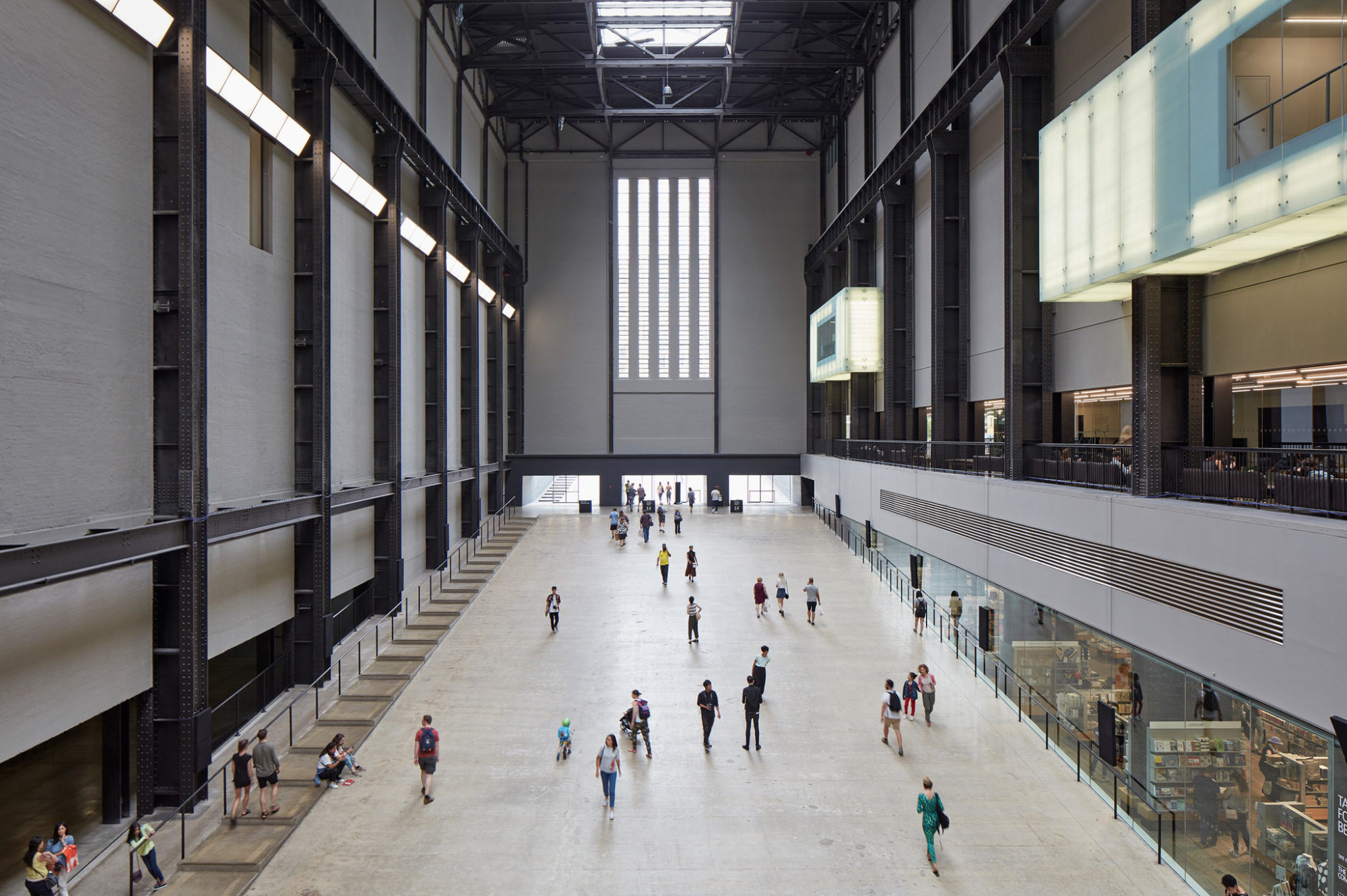
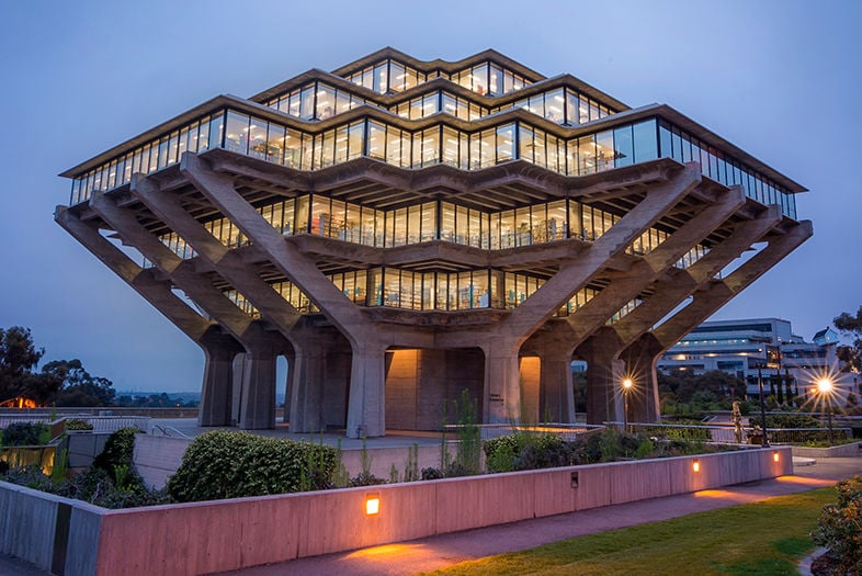
Aesthetic Exploration – Brutalism
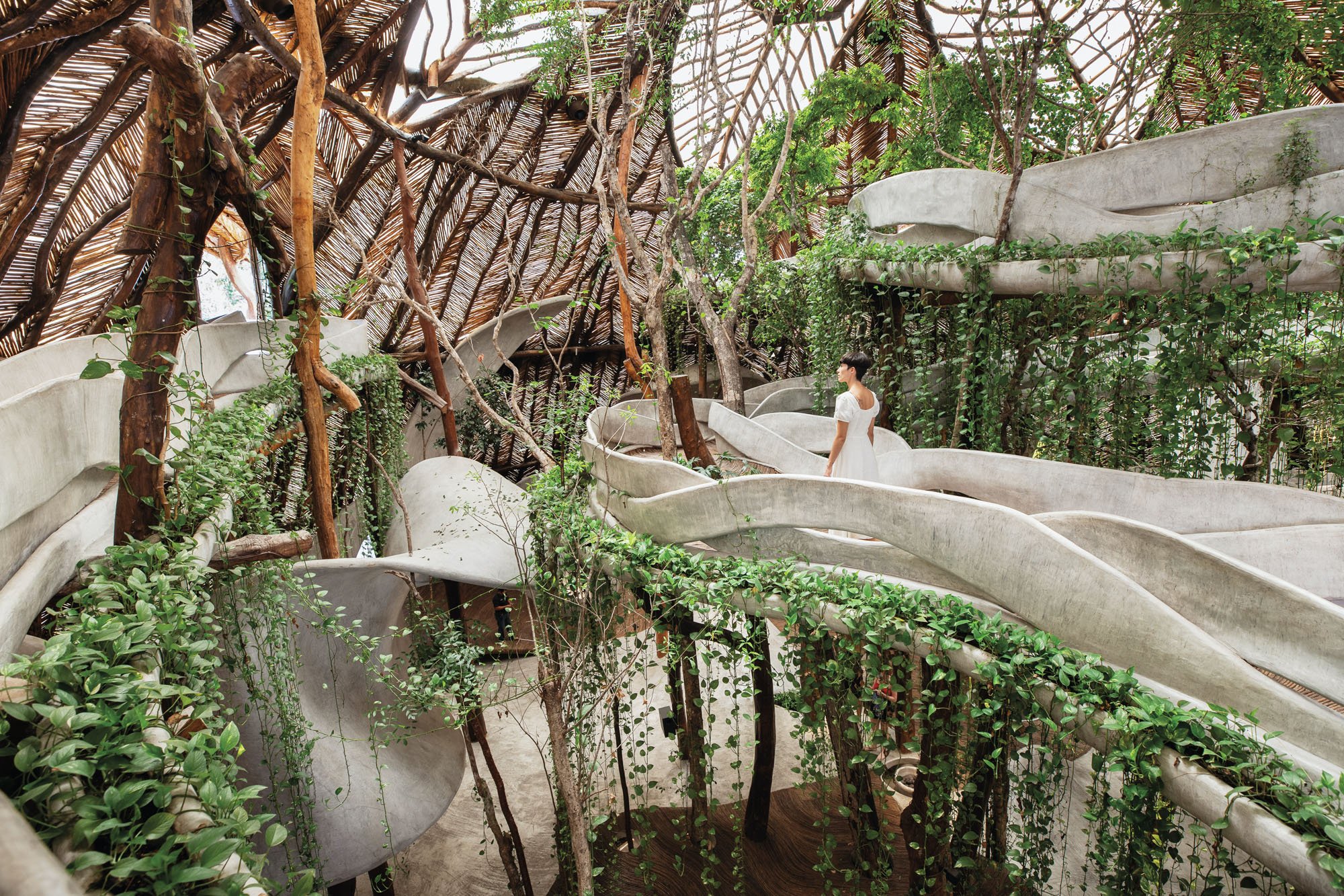
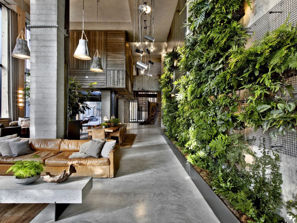
Biophilic Design
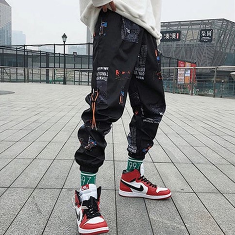
Aesthetics Exploration- Streetwear
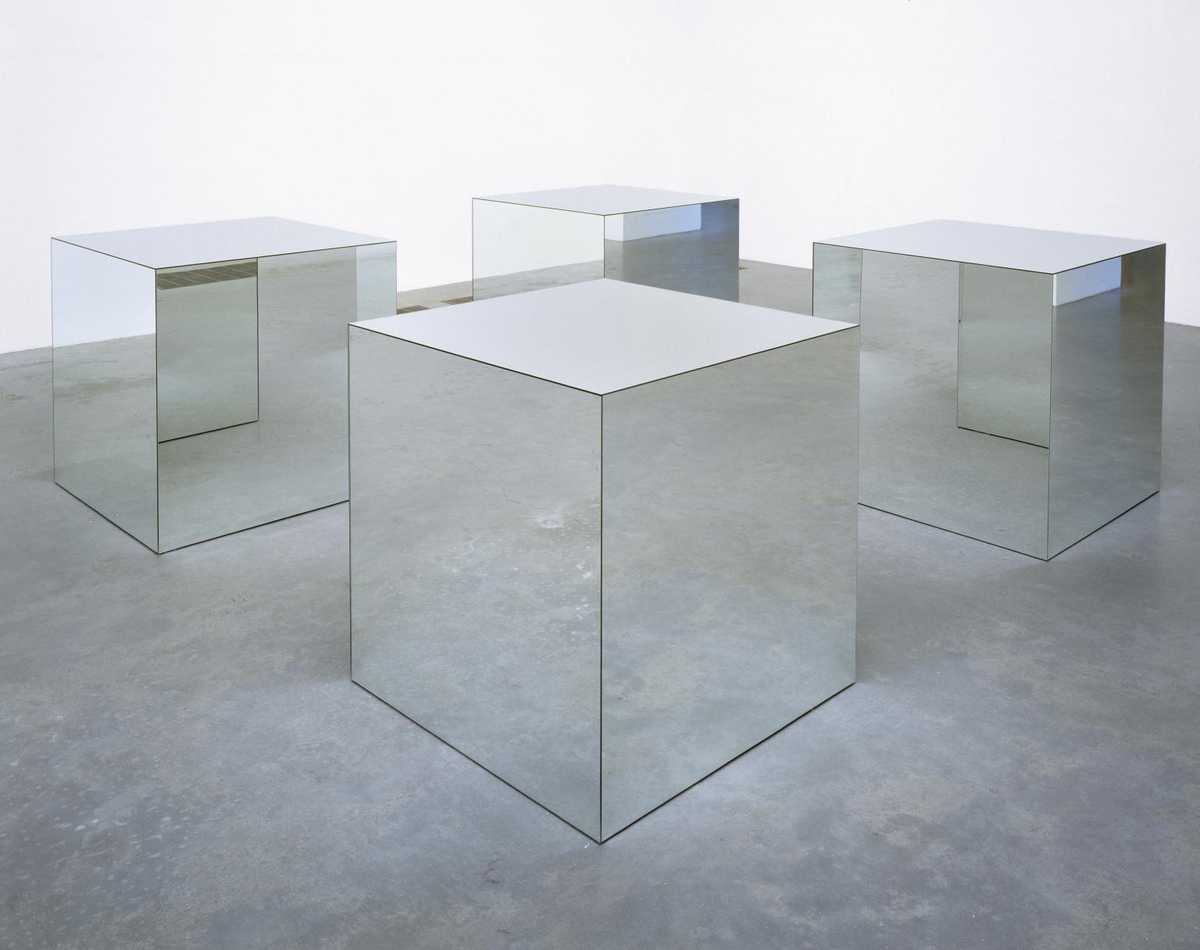
Aesthetics Exploration – Minimalism
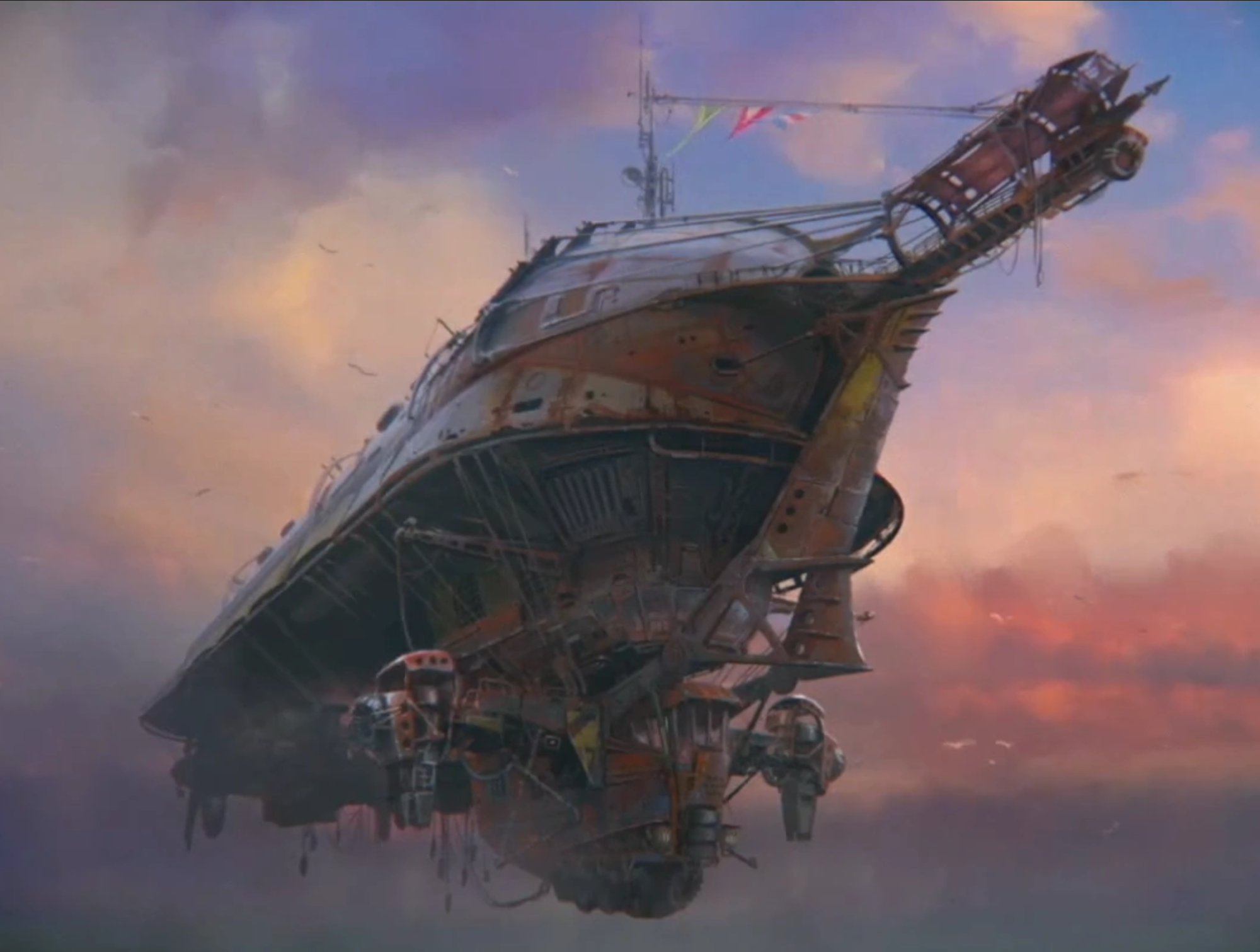
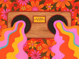
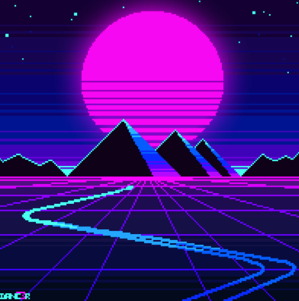
Aesthetics Exploration – Retro Futurism
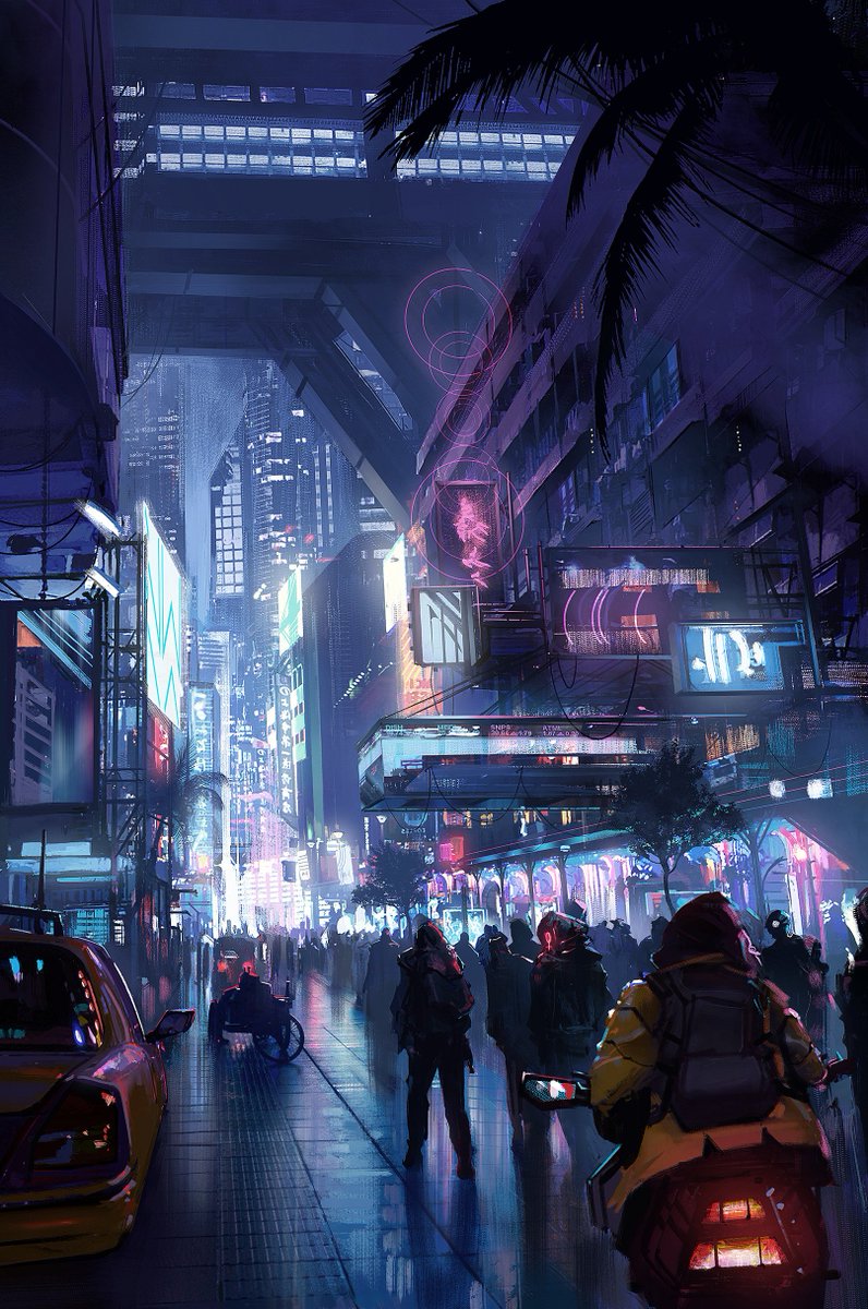
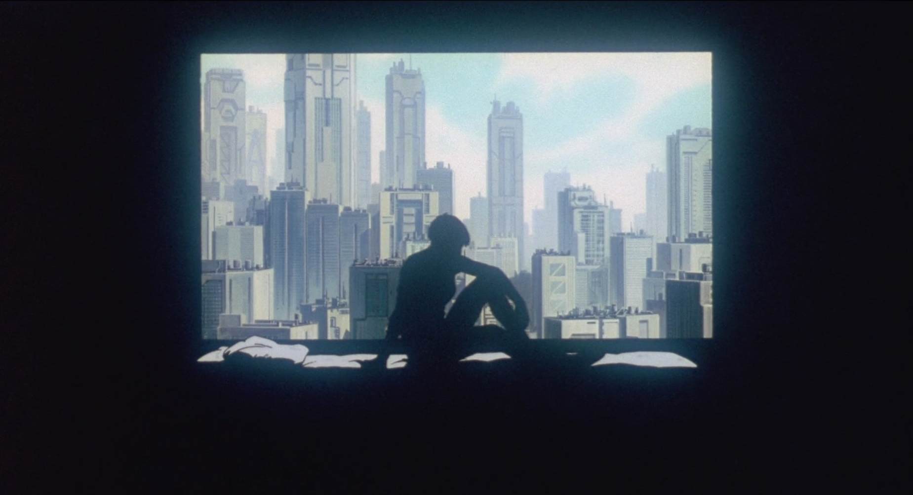
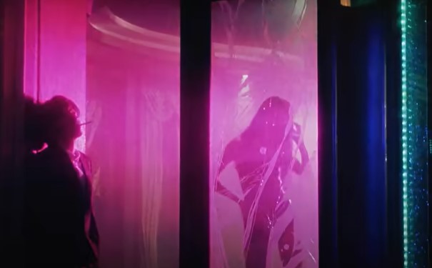
The Cyberpunk Aesthetic
Aesthetic Exploration – Minimalism
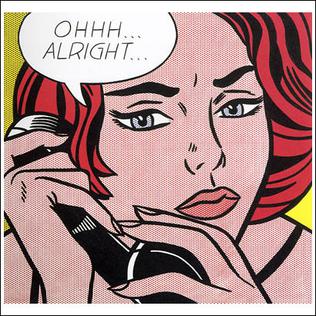
An Examination of Pop Art
Aesthetics Exploration: Minimalism – The Art of Simplicity
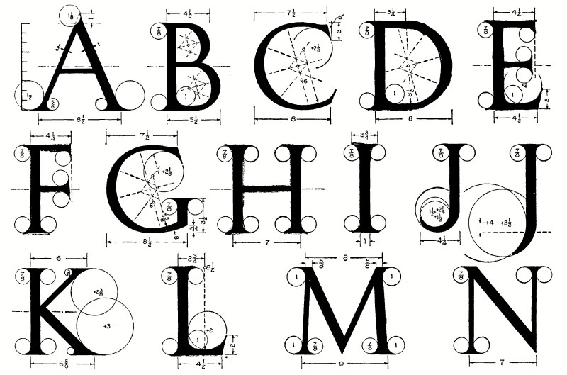
1912 Web Text about Lettering
Aesthetics exploration – Lighting
Bohemian Aesthetic
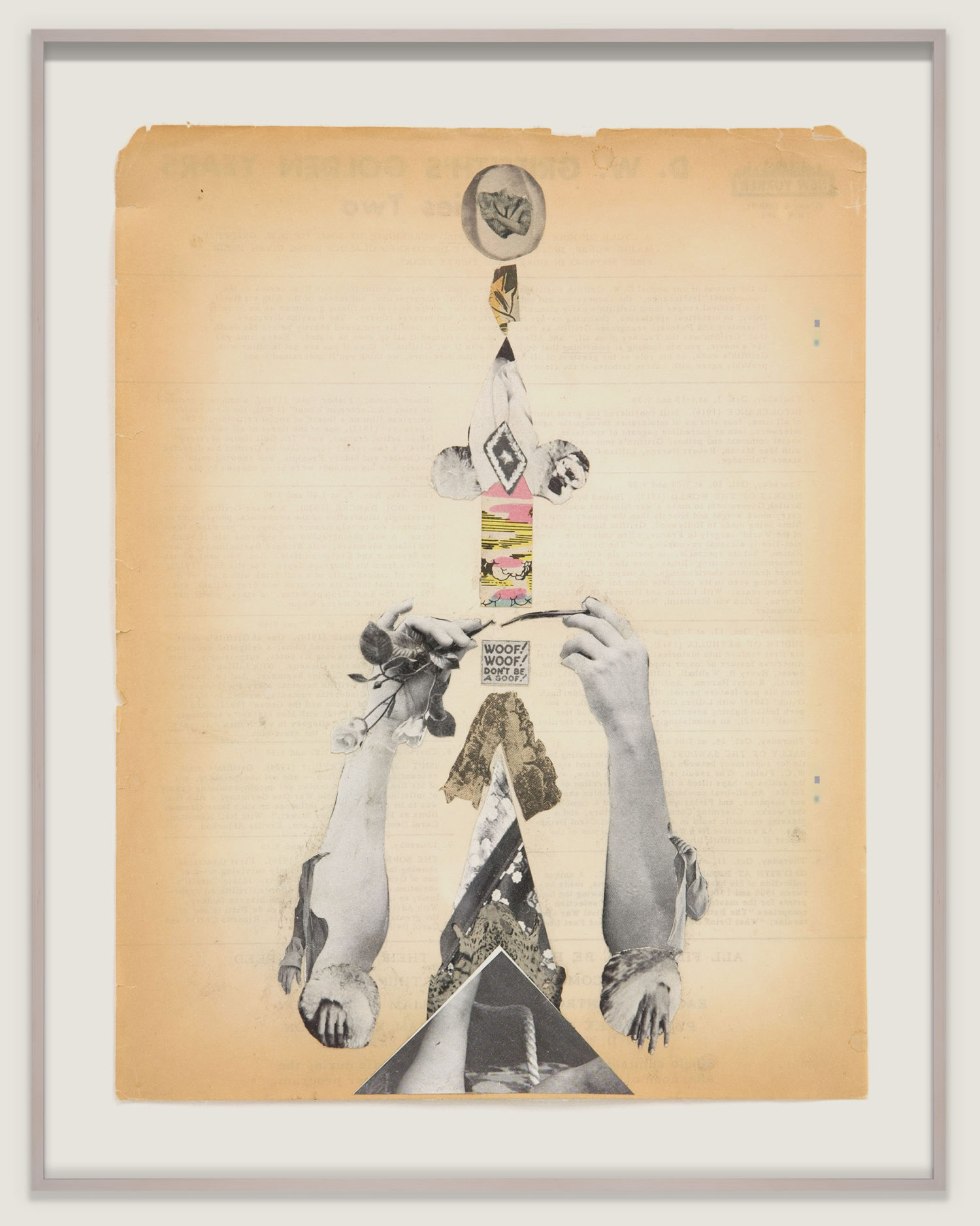
Aesthetic Exploration // Dadaism
Instagram User neptunes2000’s Outfit Pictures
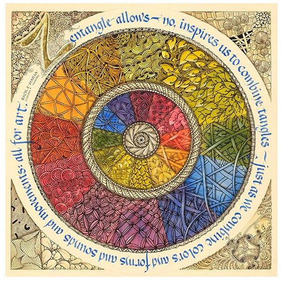
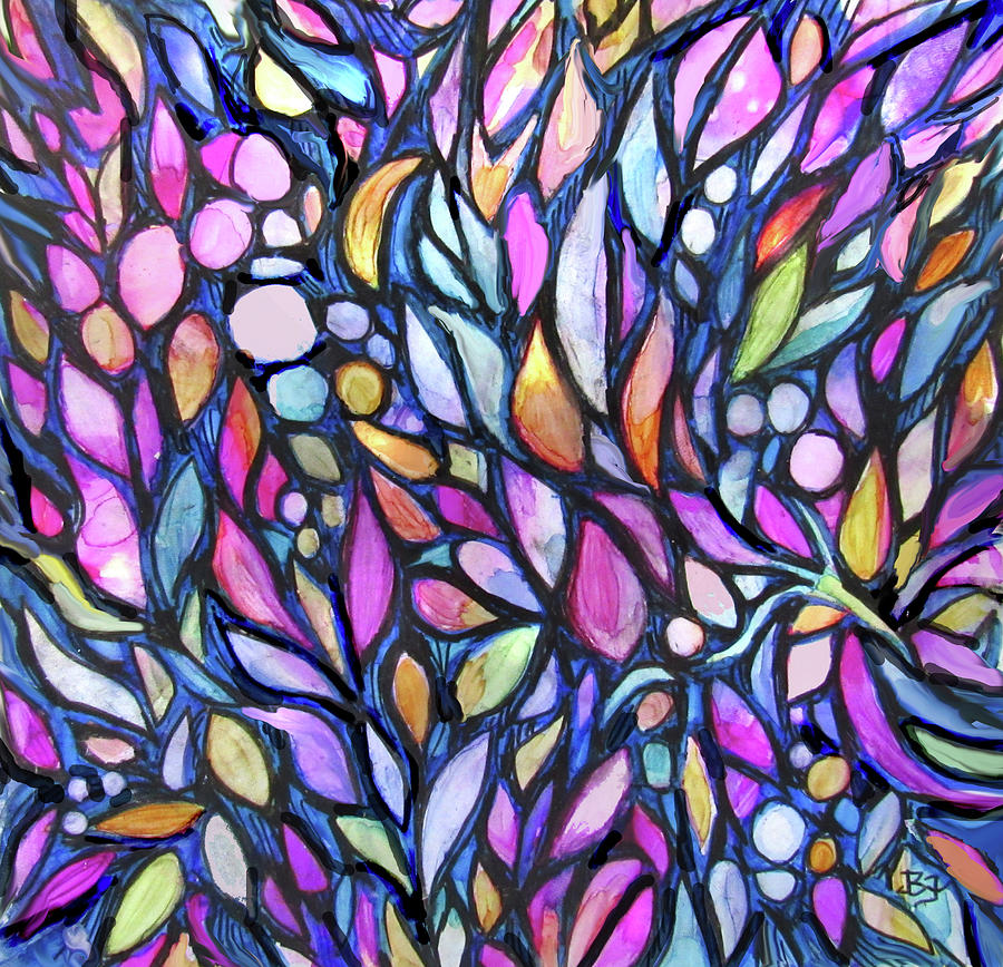
Exploration an aesthetics: Zentangle
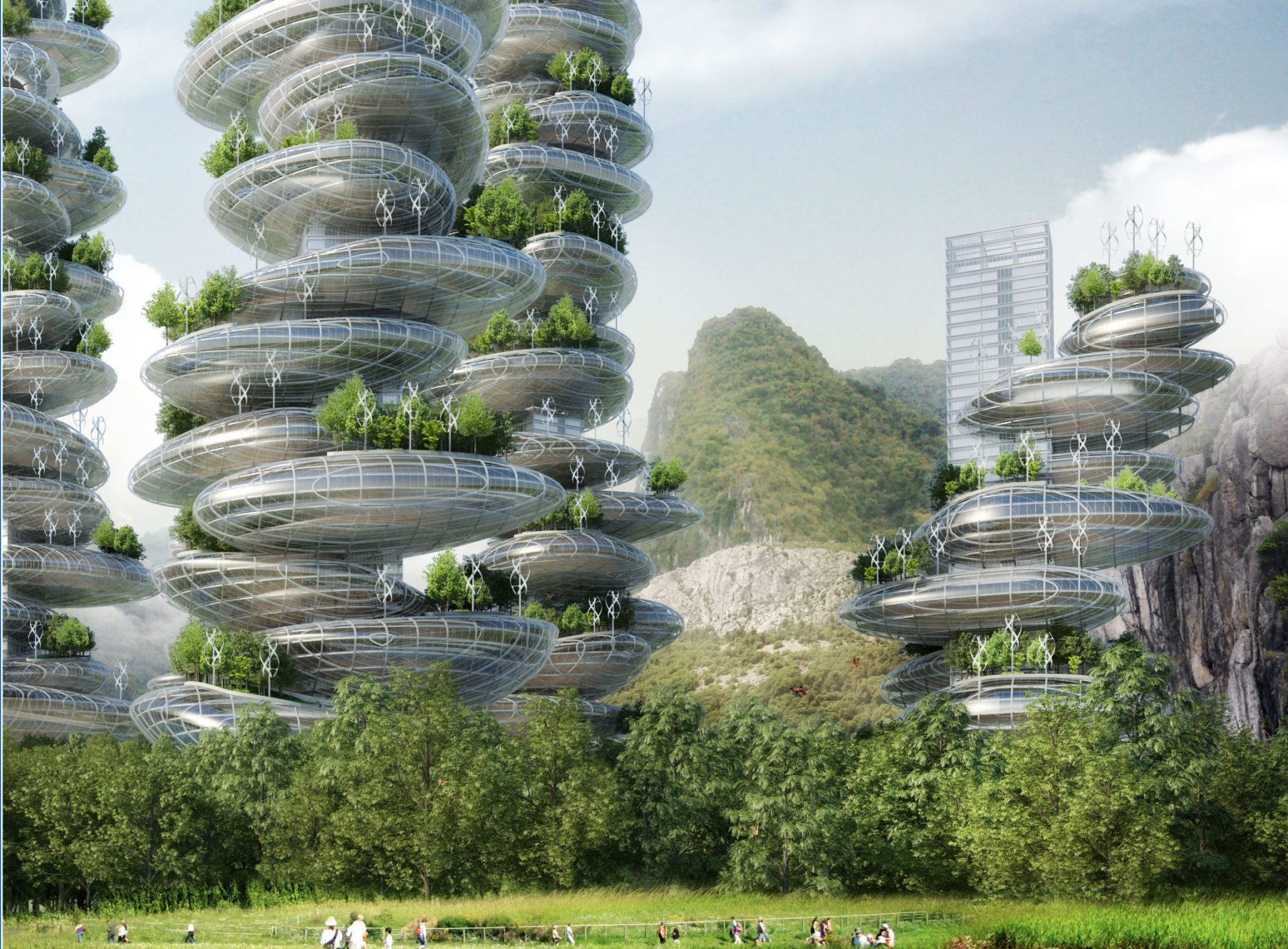
Aesthetic Exploration- SolarPunk
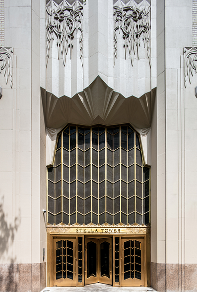
Aesthetics Exploration – Art Deco
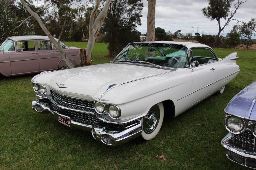
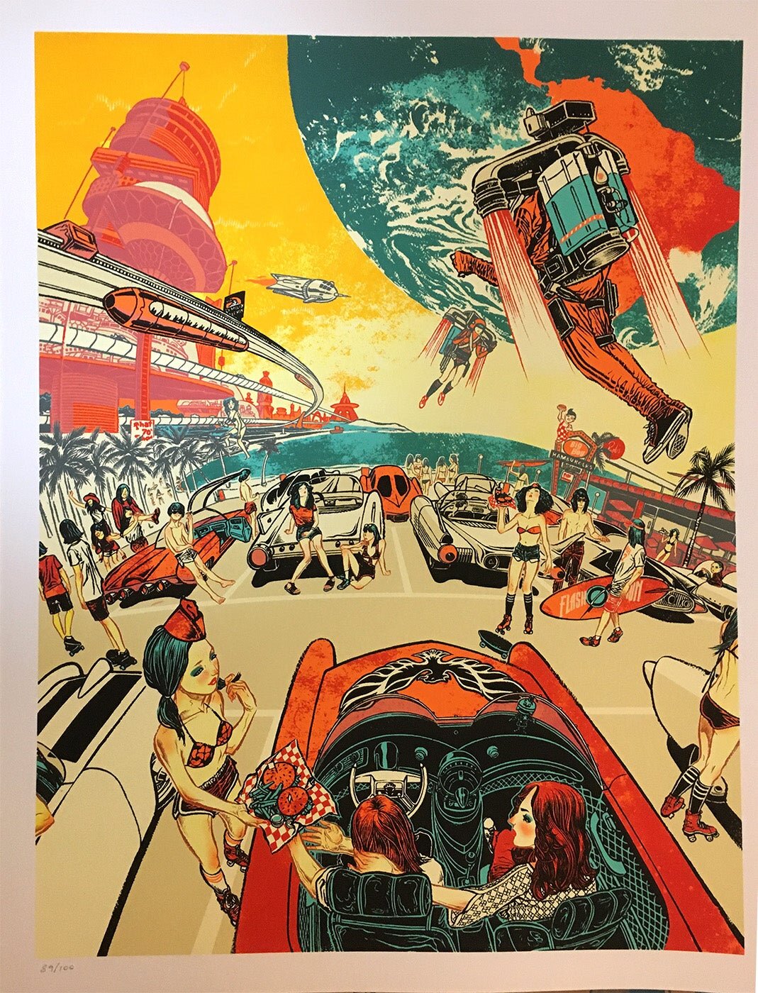
Aesthetic Exploration: 60s Show Bikes
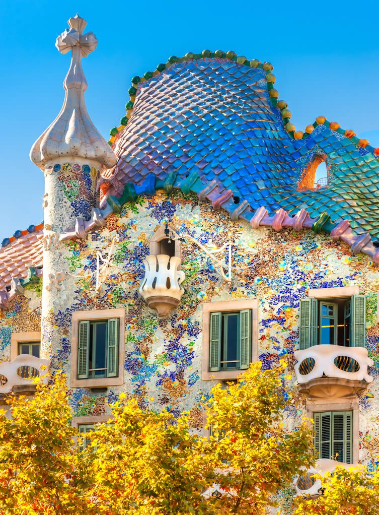
Aesthetics exploration – Catalan Modernisme in Arquitecture
Aesthetic Exploration – Art Deco
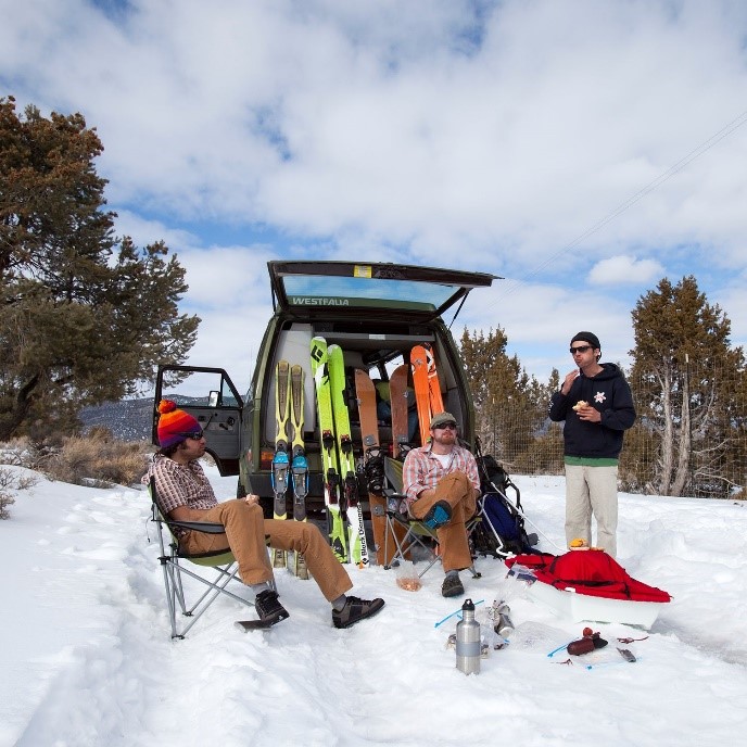
Ski Bum Aesthetic
Aesthetic Exploration – The Space Age
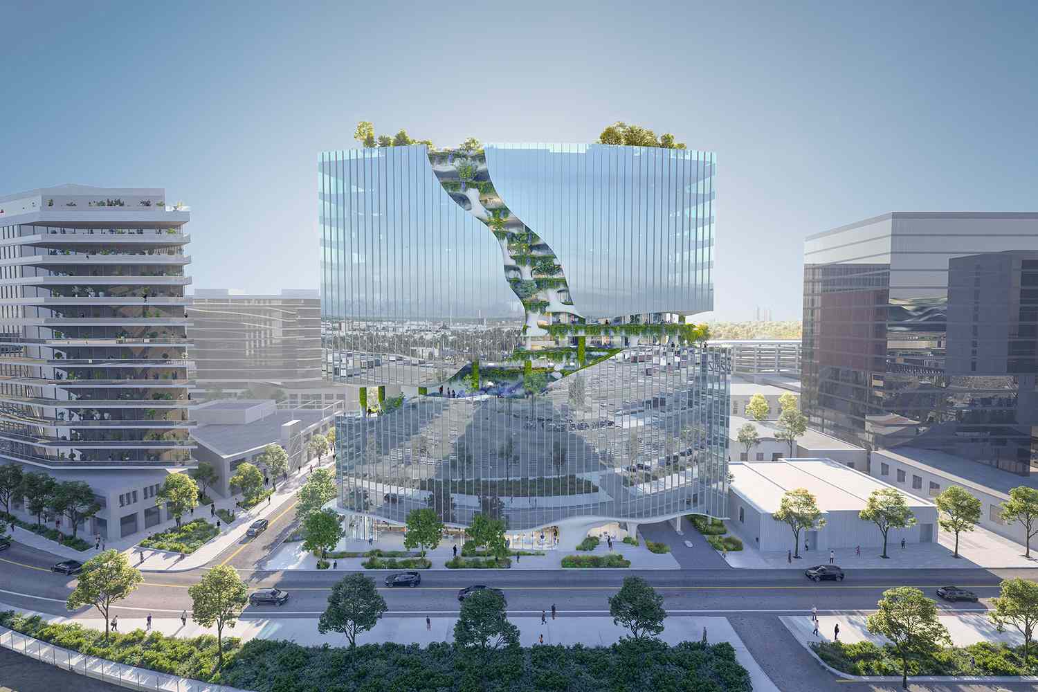
The Aesthetic of Green Cities
Aesthetic Exploration – Cyberpunk
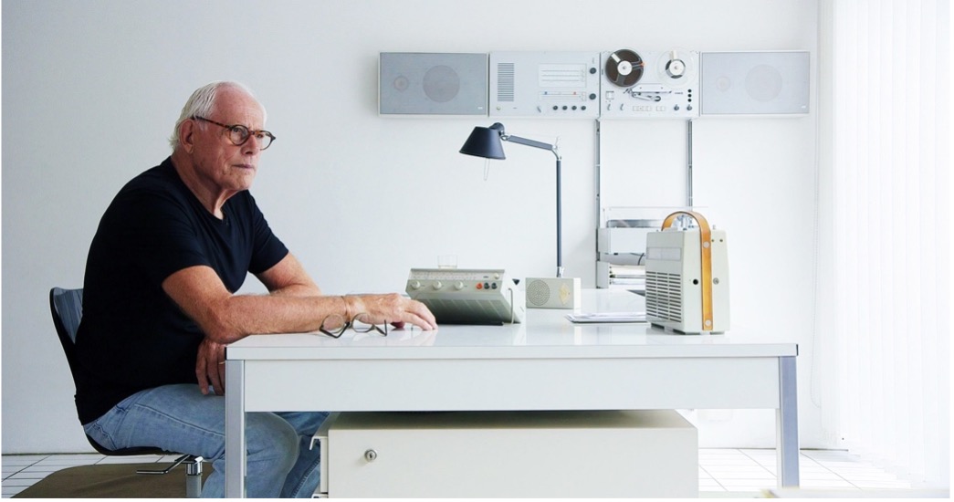
Aesthetic Exploration – The Braun Style
Aesthetic Exploration – Utilitarian Design
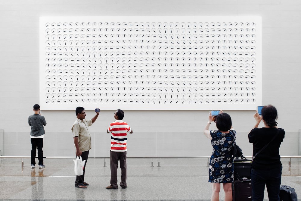
Aesthetic Exploration- A Million Times
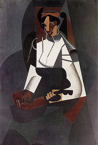
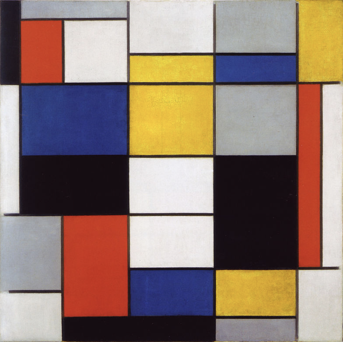
Aesthetics Exploration- Cubism
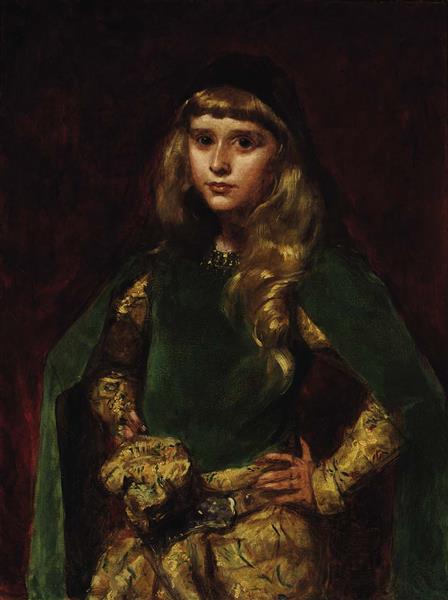
Aesthetics Exploration – Art Academia
Aesthetics Exploration – De Stijl
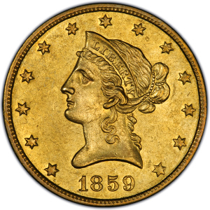
Aesthetic Exploration – American Numismatics
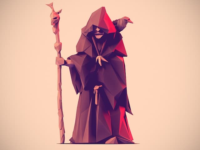
Aesthetic Exploration: Eldritch
Aesthetic of the Incomplete
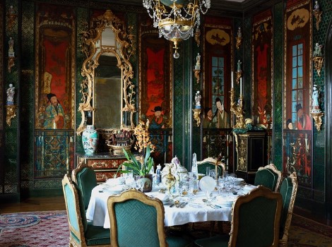
Maximalism as an Aesthetic
Aesthetic Exploration – Blobject
Industrial Design Aesthetic
Aesthetic Exploration: 70’s
Industrial Aesthetic
Aesthetics Exploration – Outrun
Aesthetic Exploration – Whimsical Aesthetic
Aesthetic Exploration- BRTHR
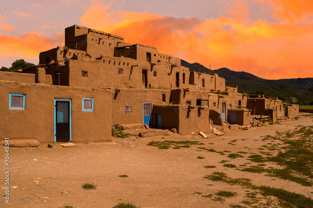
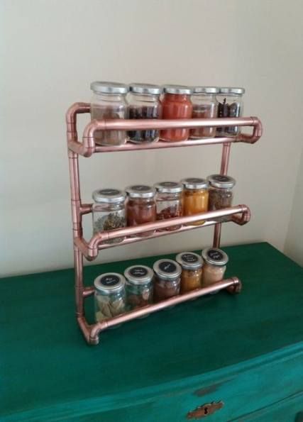
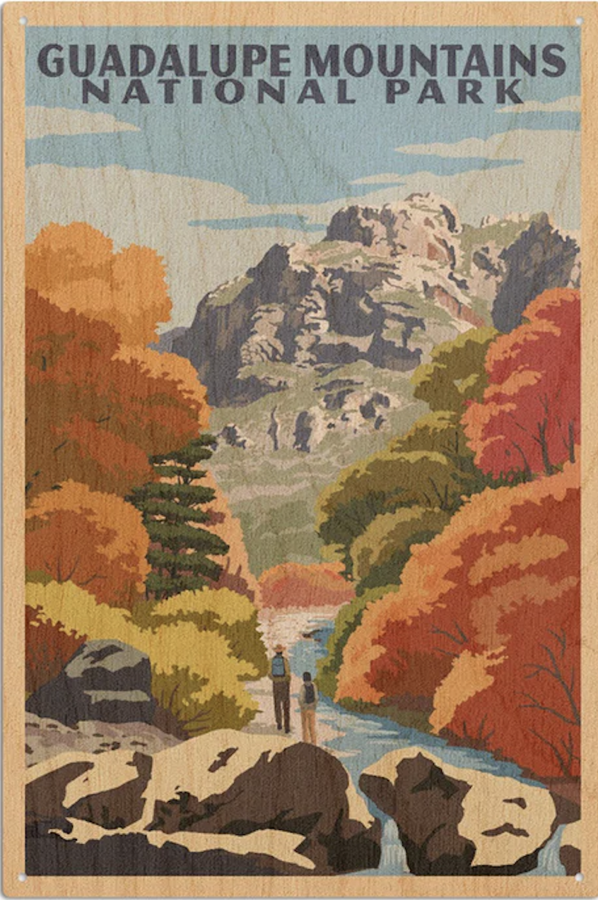
Aesthetic Exploration – Southwestern
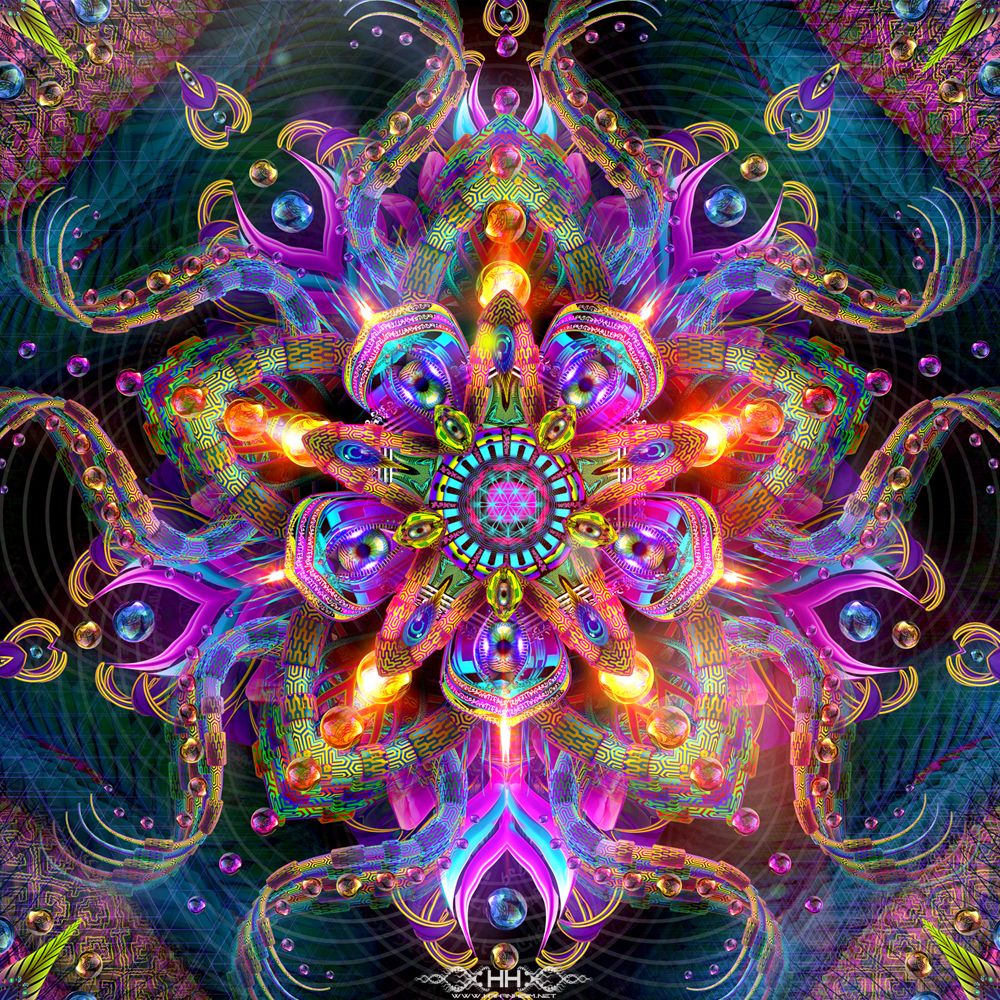
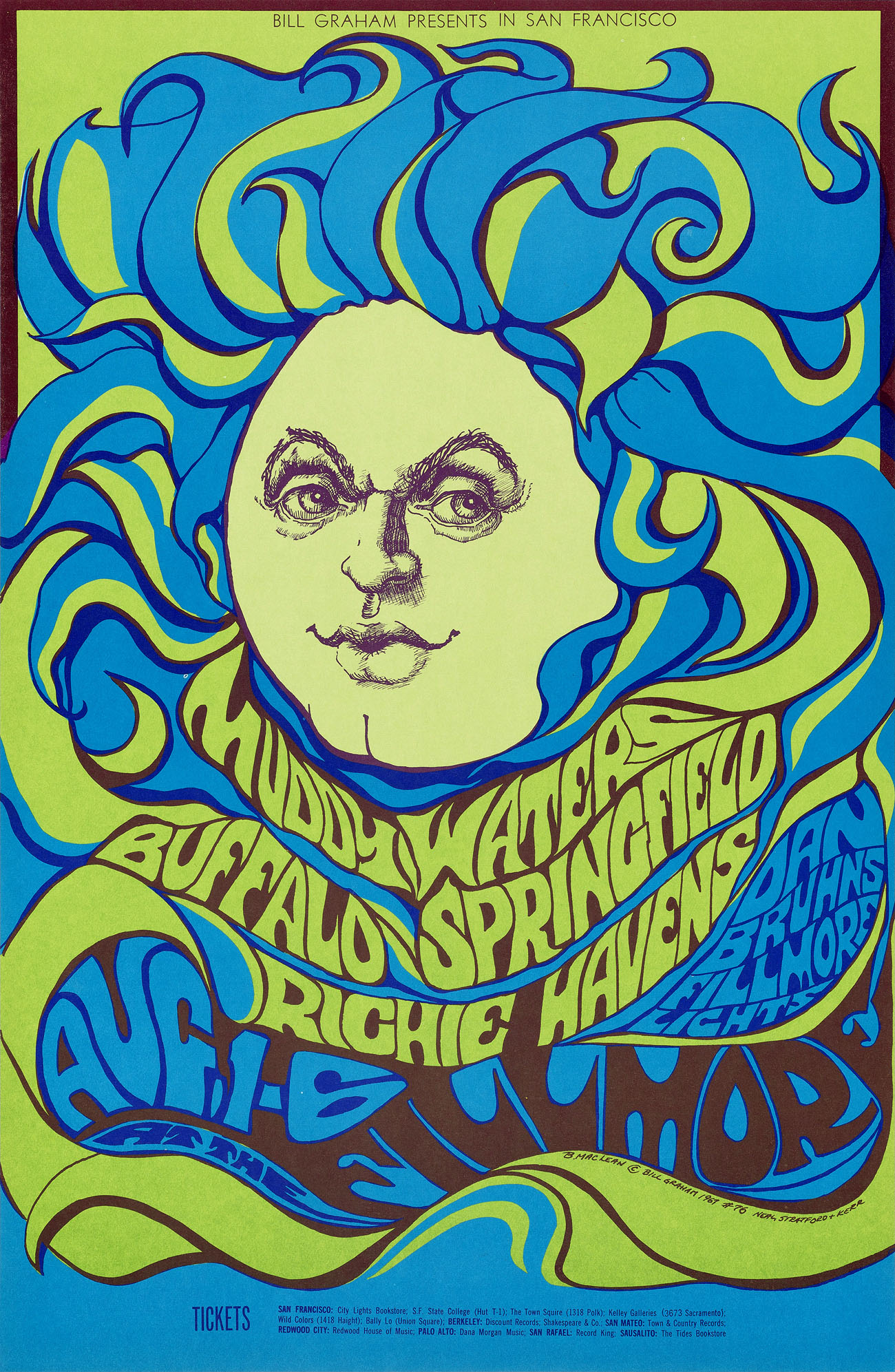
Aesthetics Exploration – Psychedelic
Superflat Aesthetic
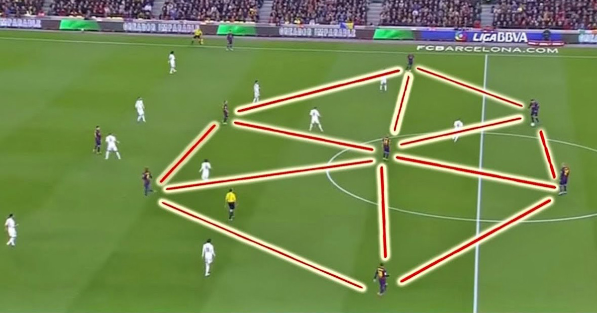
Tiki Taka: An Aesthetic of Soccer
Midcentury Modern Aesthetic
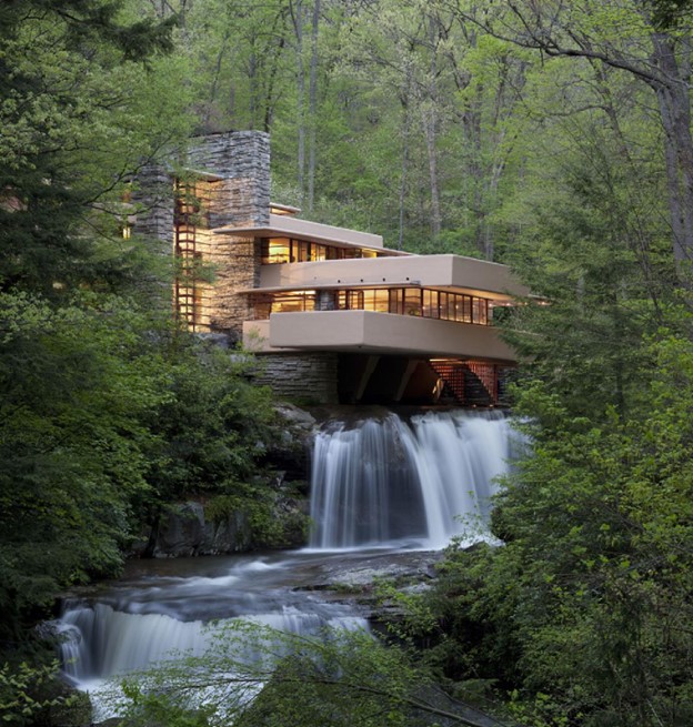
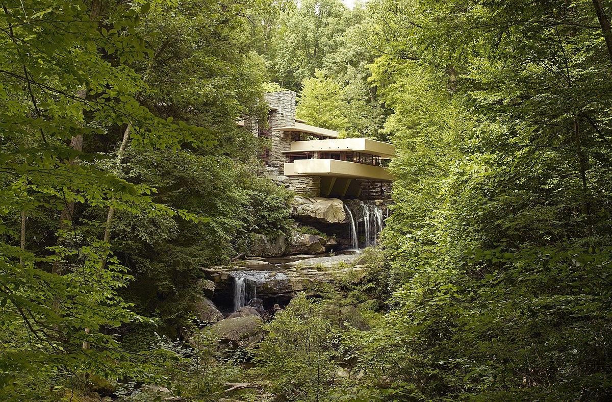
Organic Architecture Aesthetic Exploration
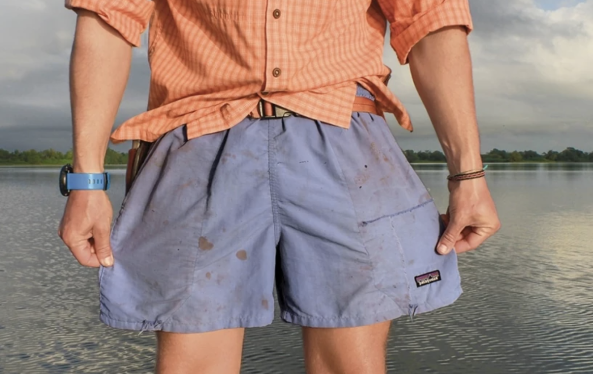
Dirtbag Aesthetic Exploration
Aesthetics Exploration – Ma(間)
Aesthetic Exploration- Retro-Futuristism
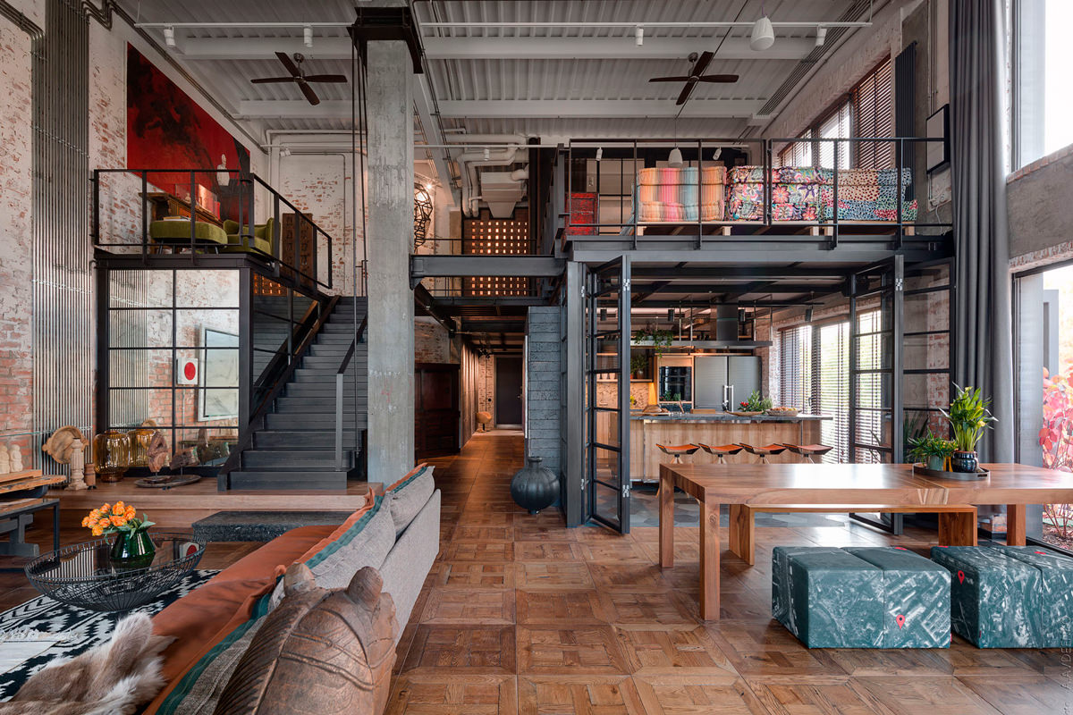
From Factories to Furnishings: Industrial Chic
Aesthetic Exploration – 60’s and 70’s Concert Poster Art
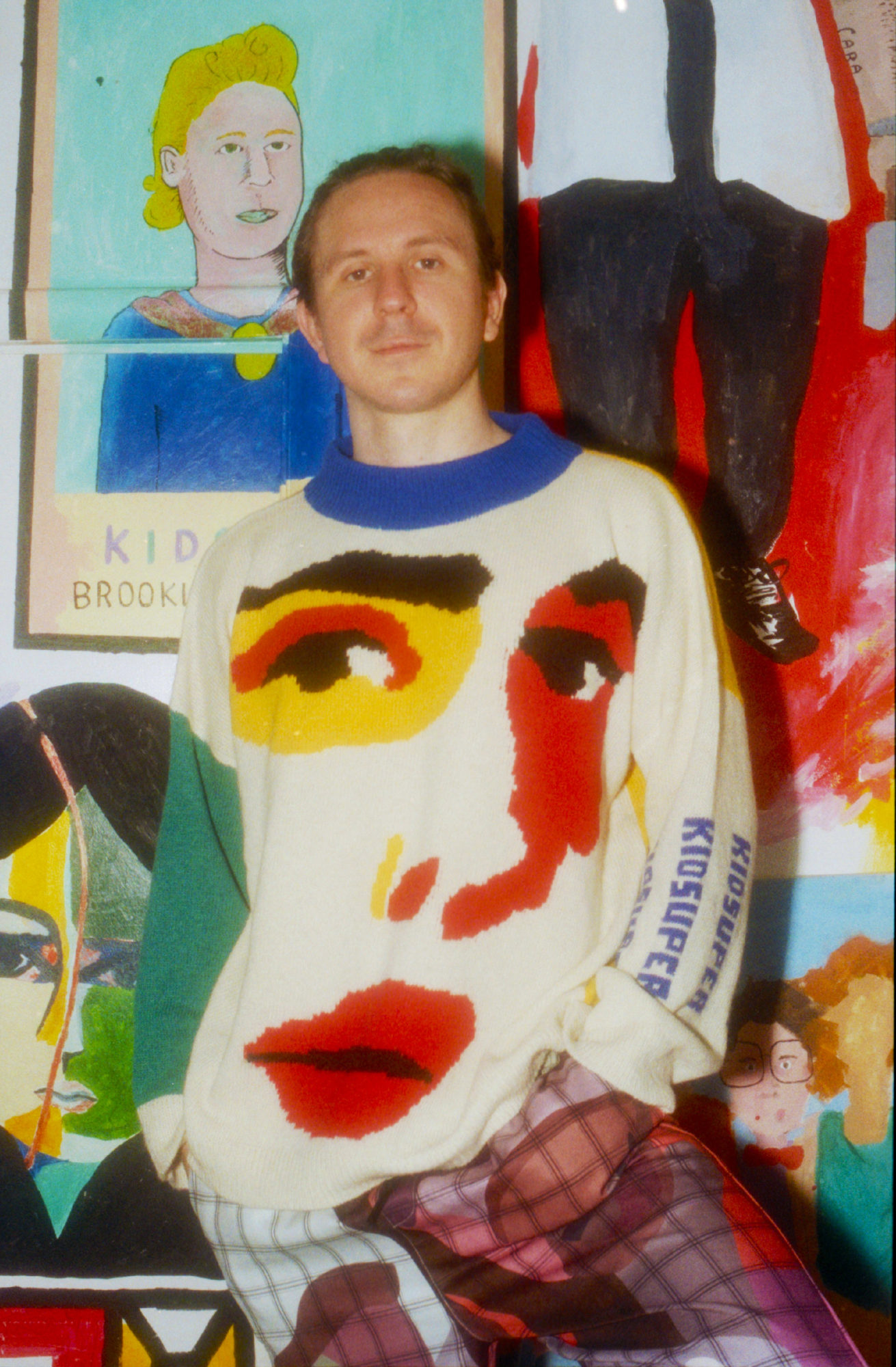
Aesthetic Exploration – KidSuper: Colm Dillane’s Whimsical Approach to High Fashion
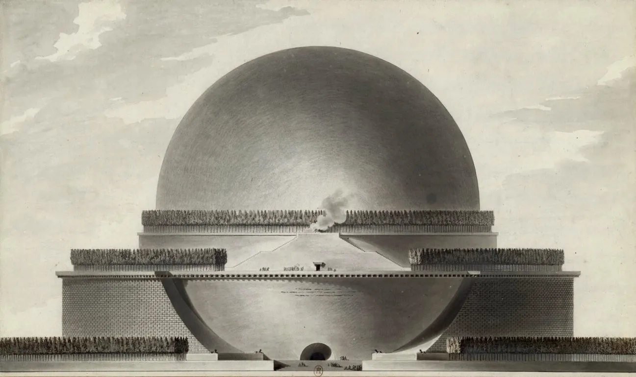
Aesthetic Exploration – Architecture Parlante
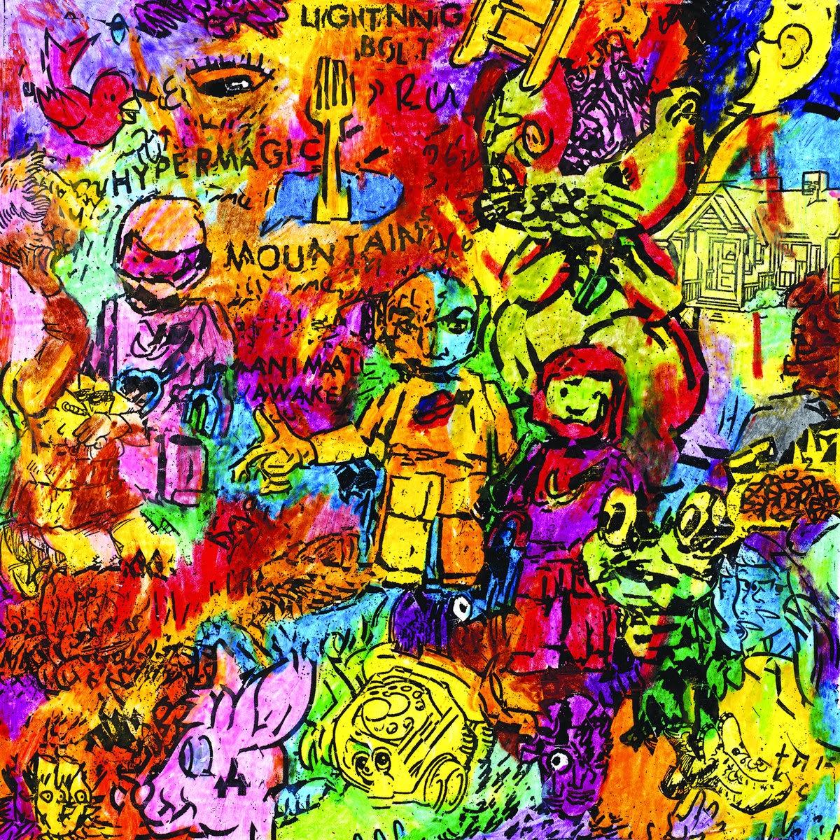
Aesthetics Exploration :- MAXIMALISM
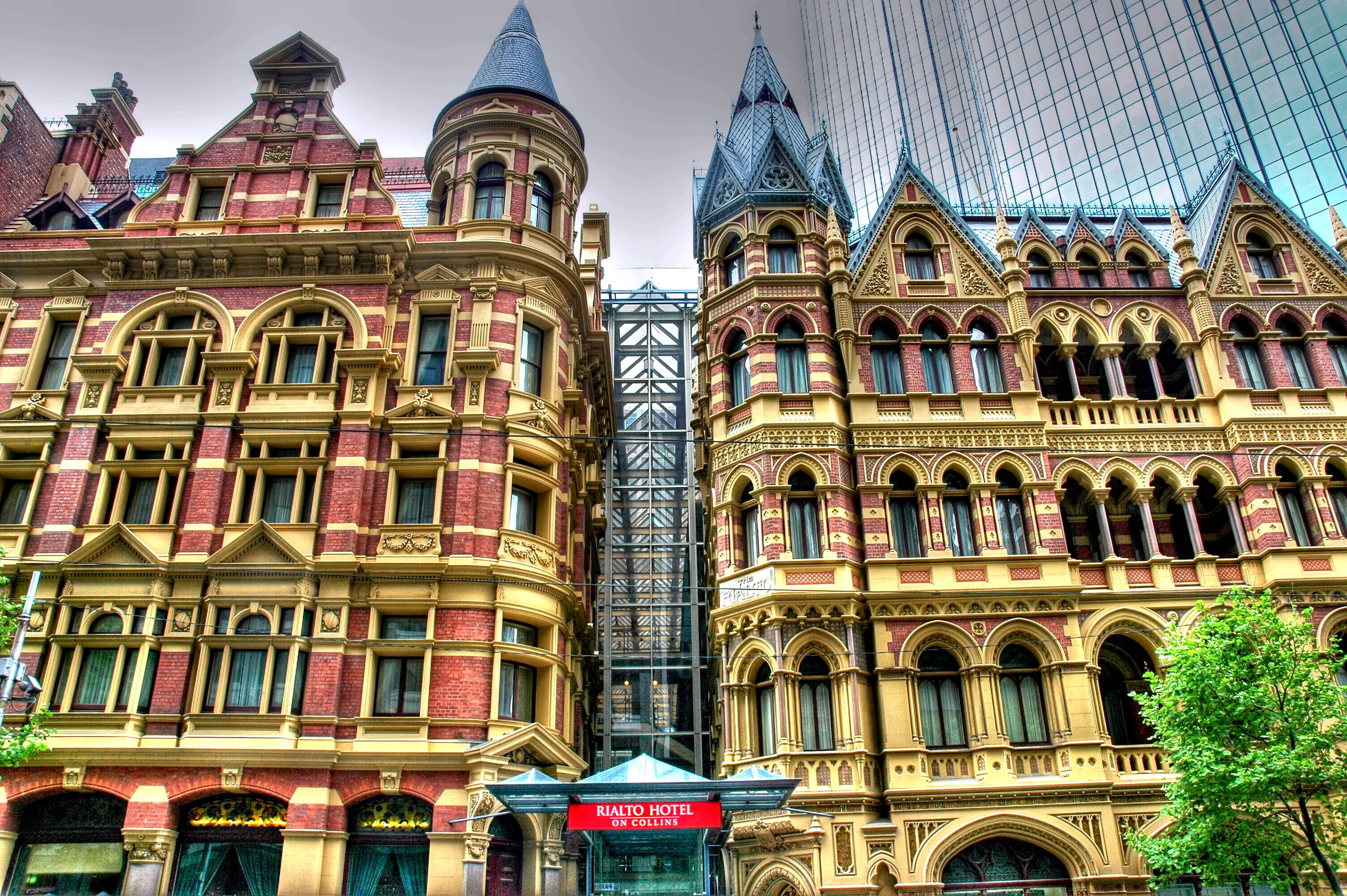
Aesthetic Exploration: Victorian Architecture
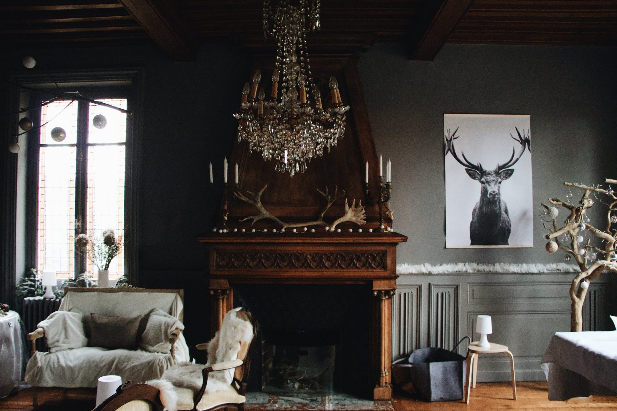
Aesthetics of Modern Gothic Design
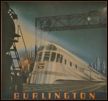
Streamline Moderne: Simplified Art Deco
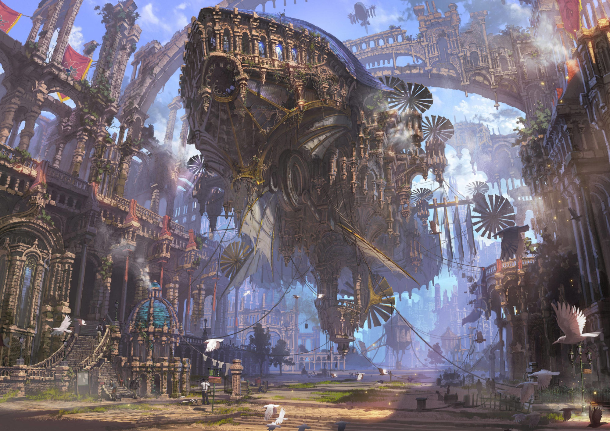
Aesthetic Exploration – Steampunk
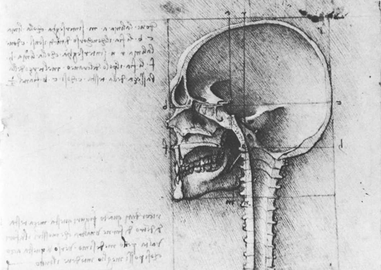
Aesthetic Exploration – Art of Human Anatomy
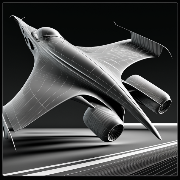
Aesthetics Exploration: Aerodynamic Design
Aesthetic Exploration: Magewave
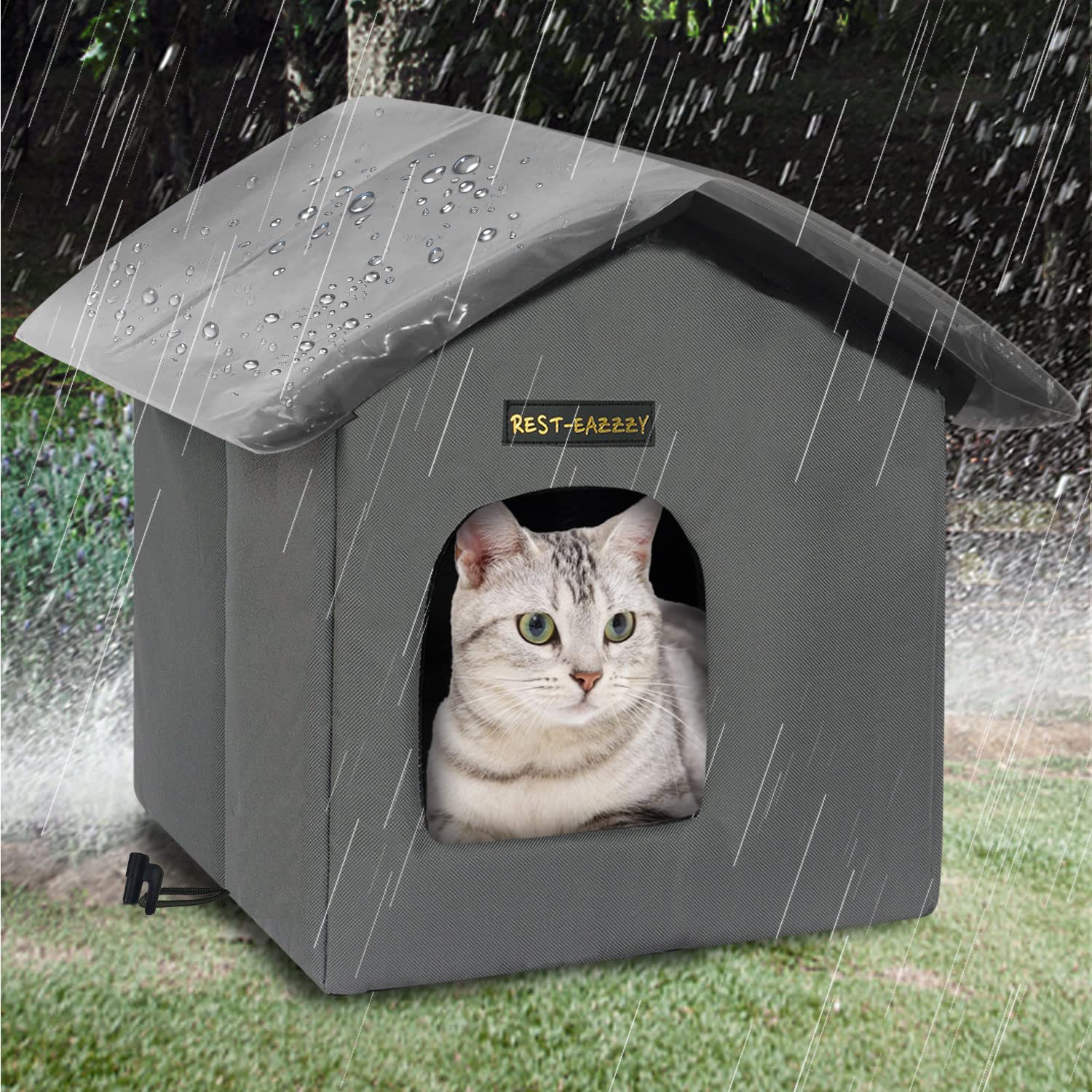
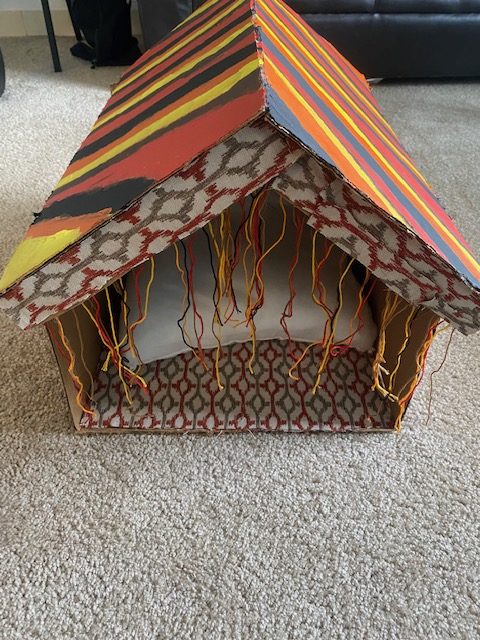
Upcycle Cat House – 70’s Theme
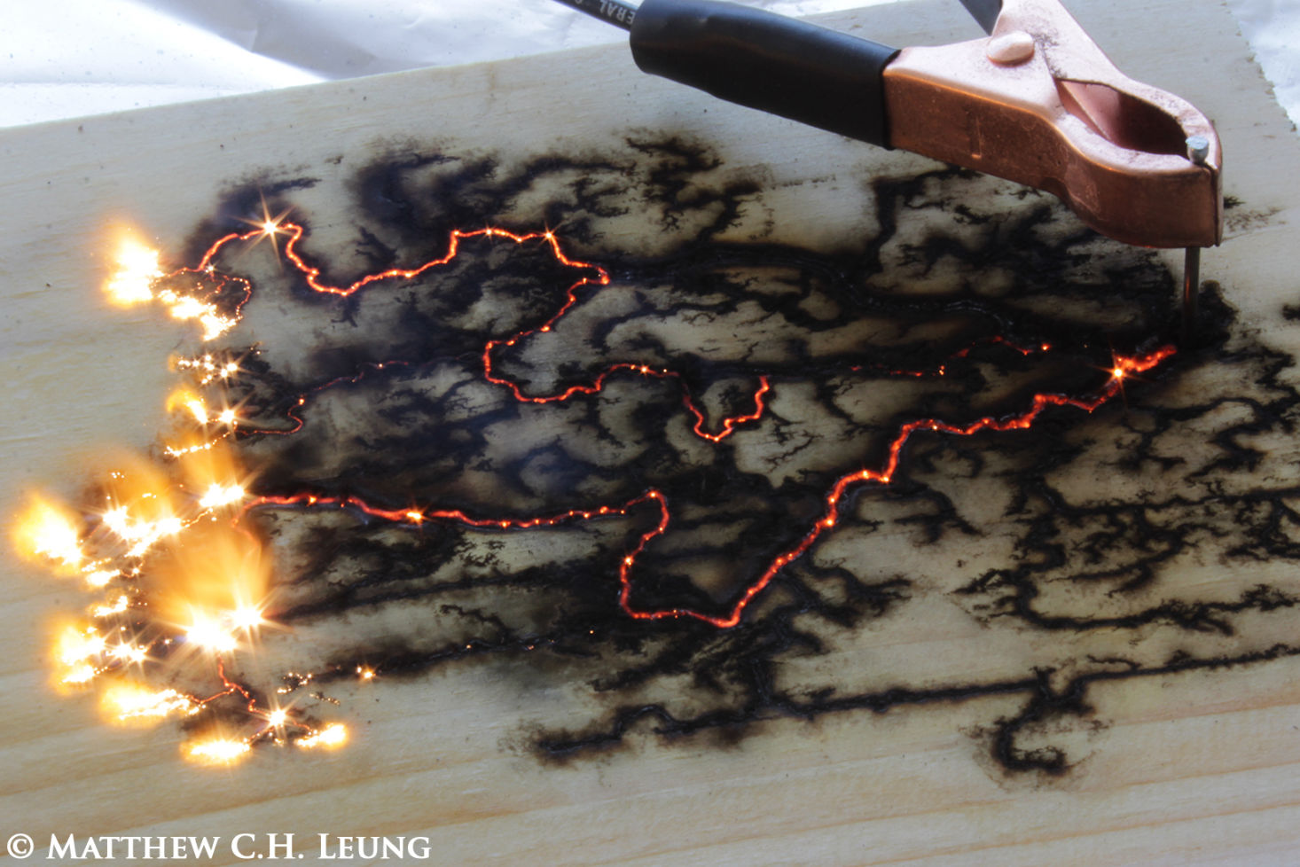
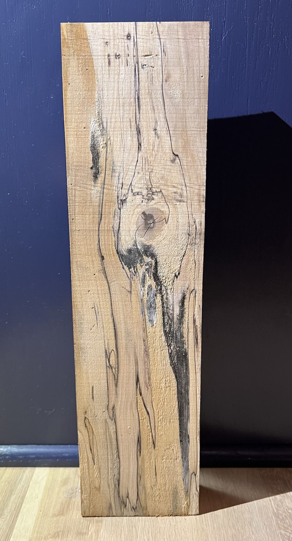
Upcycle Wood Wall Piece – Rustic/ Fractal Burn aesthetic
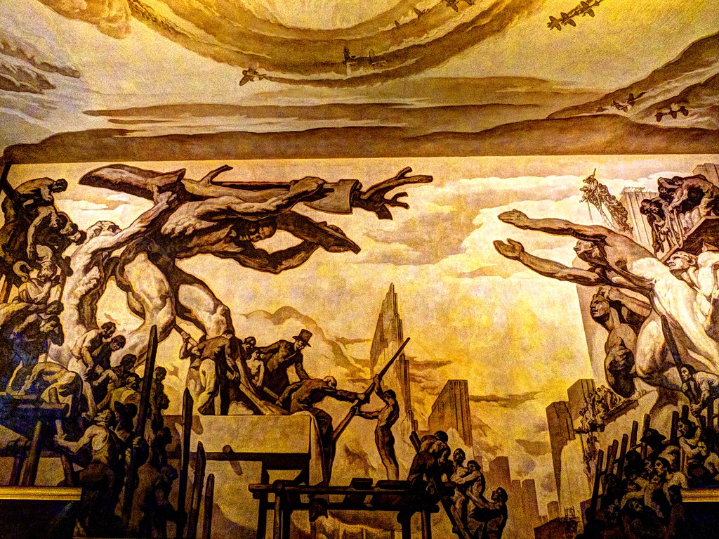
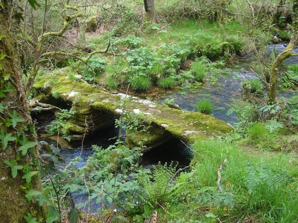
Nature vs Humanity
Keyboard Upcycle – Pixel Art Aesthetic
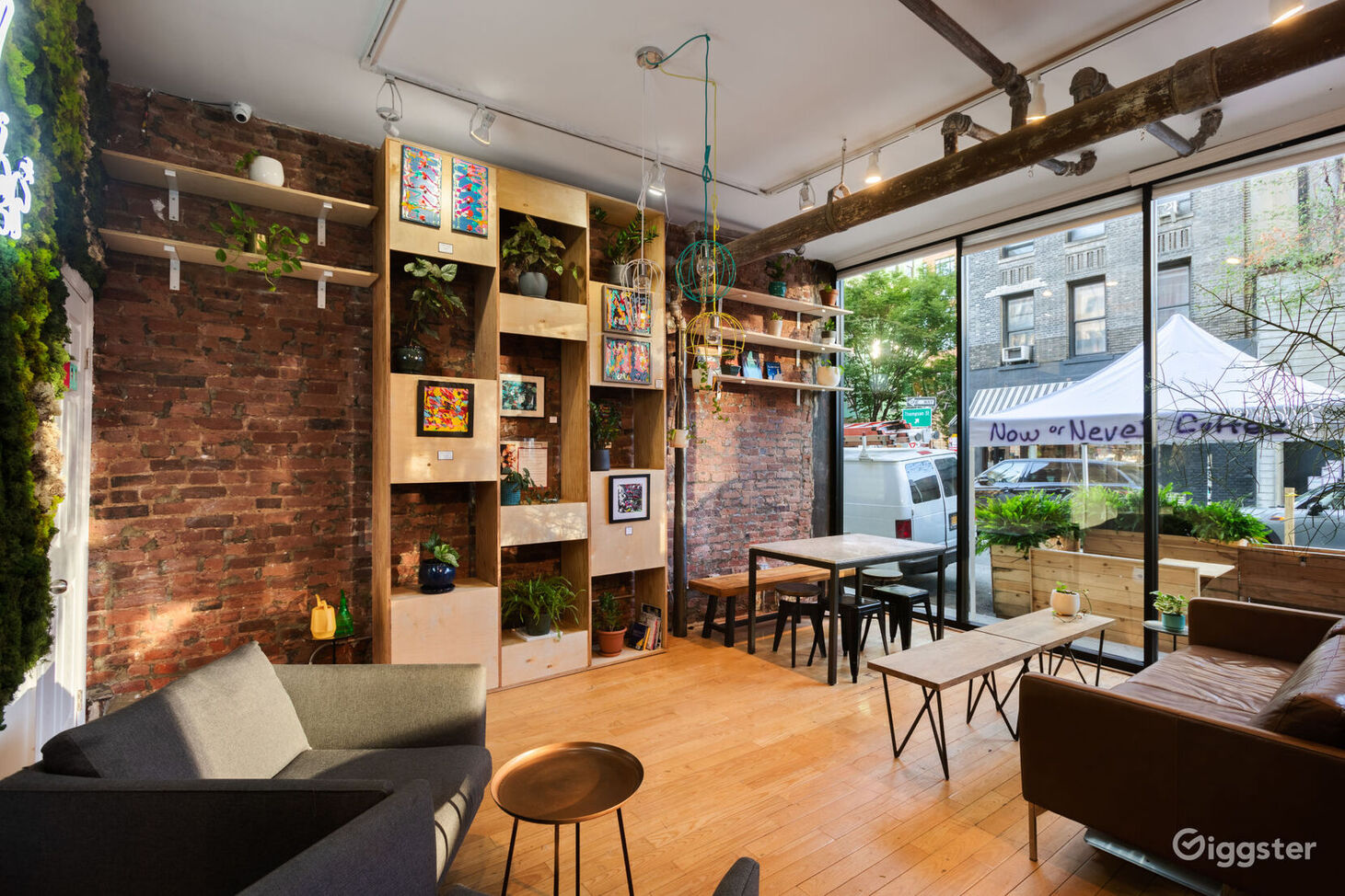
Choosing the Coffee House Aesthetic for an Upcycling Project
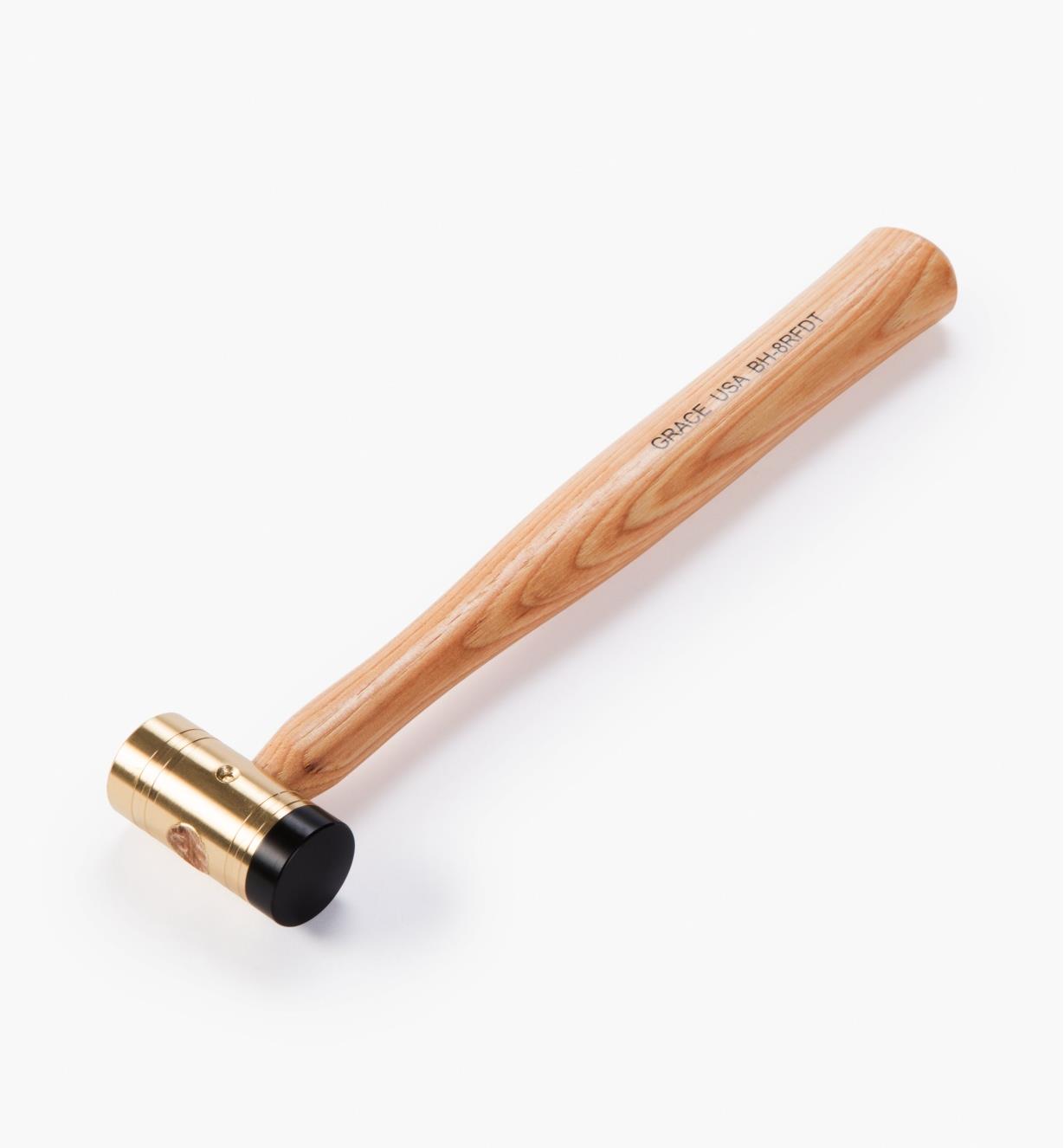
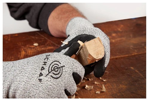
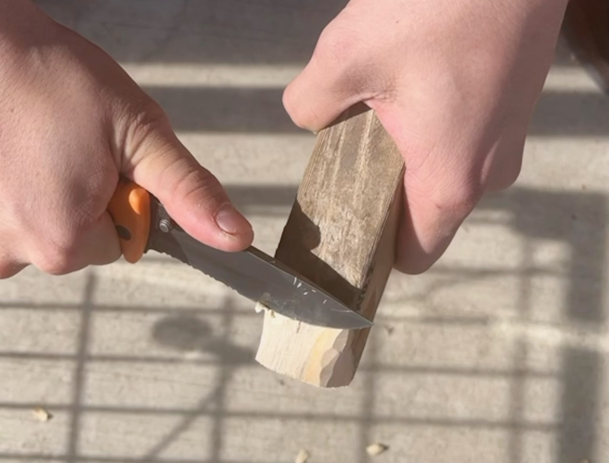
Functionalist Hammer upcycle
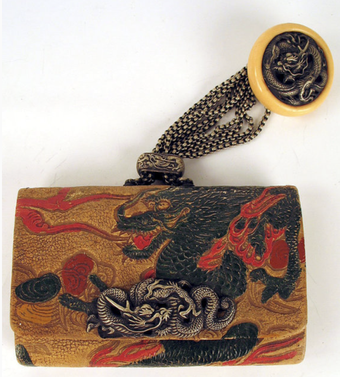
Upcycled Tobacco Pouch with Traditional Japanese Aesthetic
Upcycle Project with Aesthetic of Minimalism
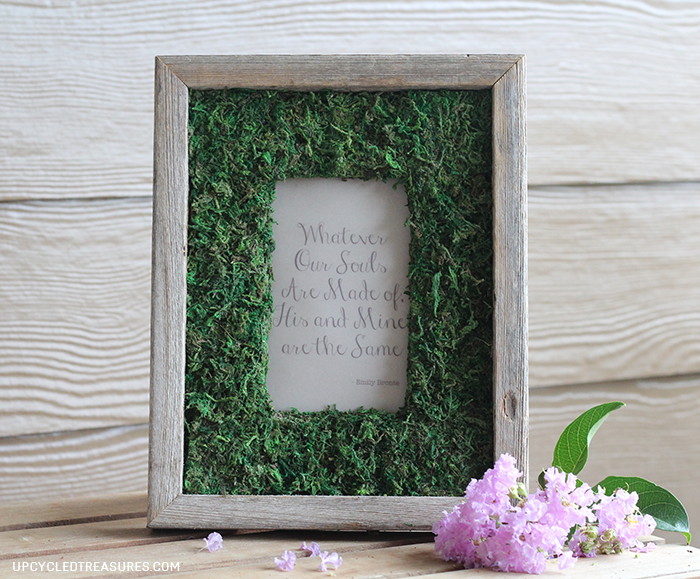
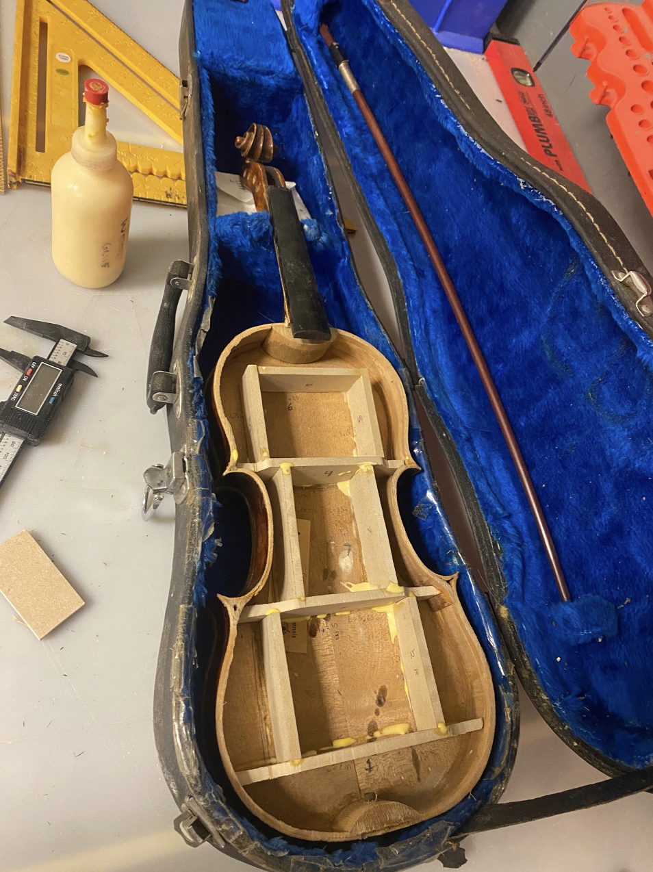
Violin Picture Frame
Upcycling Aesthetic – Installation art and Absurdism
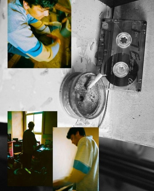
Upcycling Aesthetic – 35mm Film Collage with Planters
Upcycling Aesthetic \\ Heider Iacometti
Industrial Design Aesthetic Upcycle project
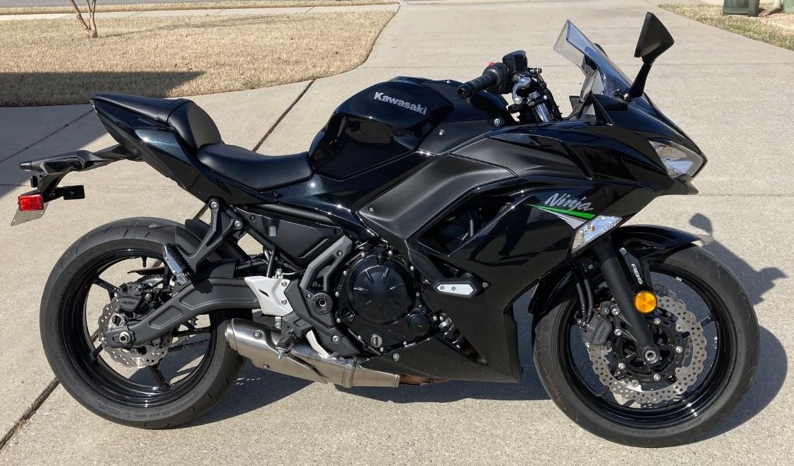
Cruiser/Café Racer Style (Desktop Paperweight)
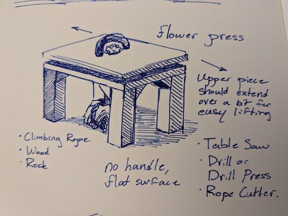
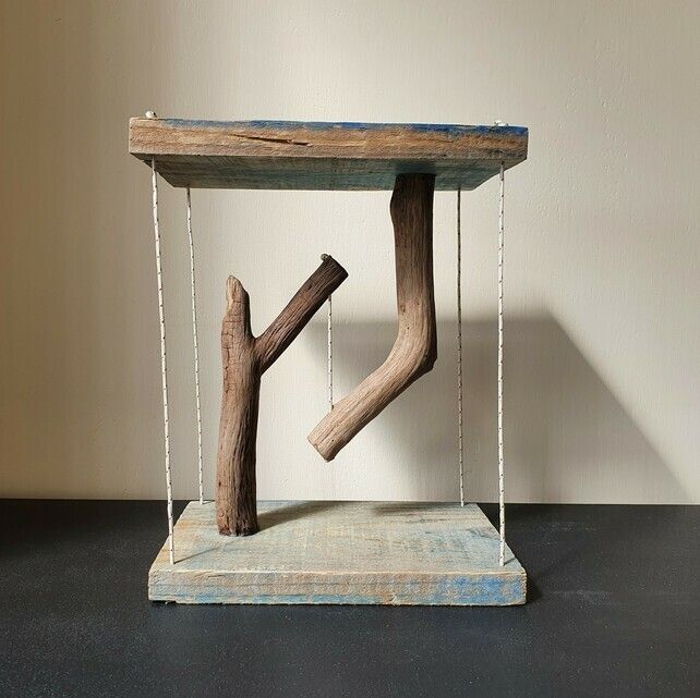
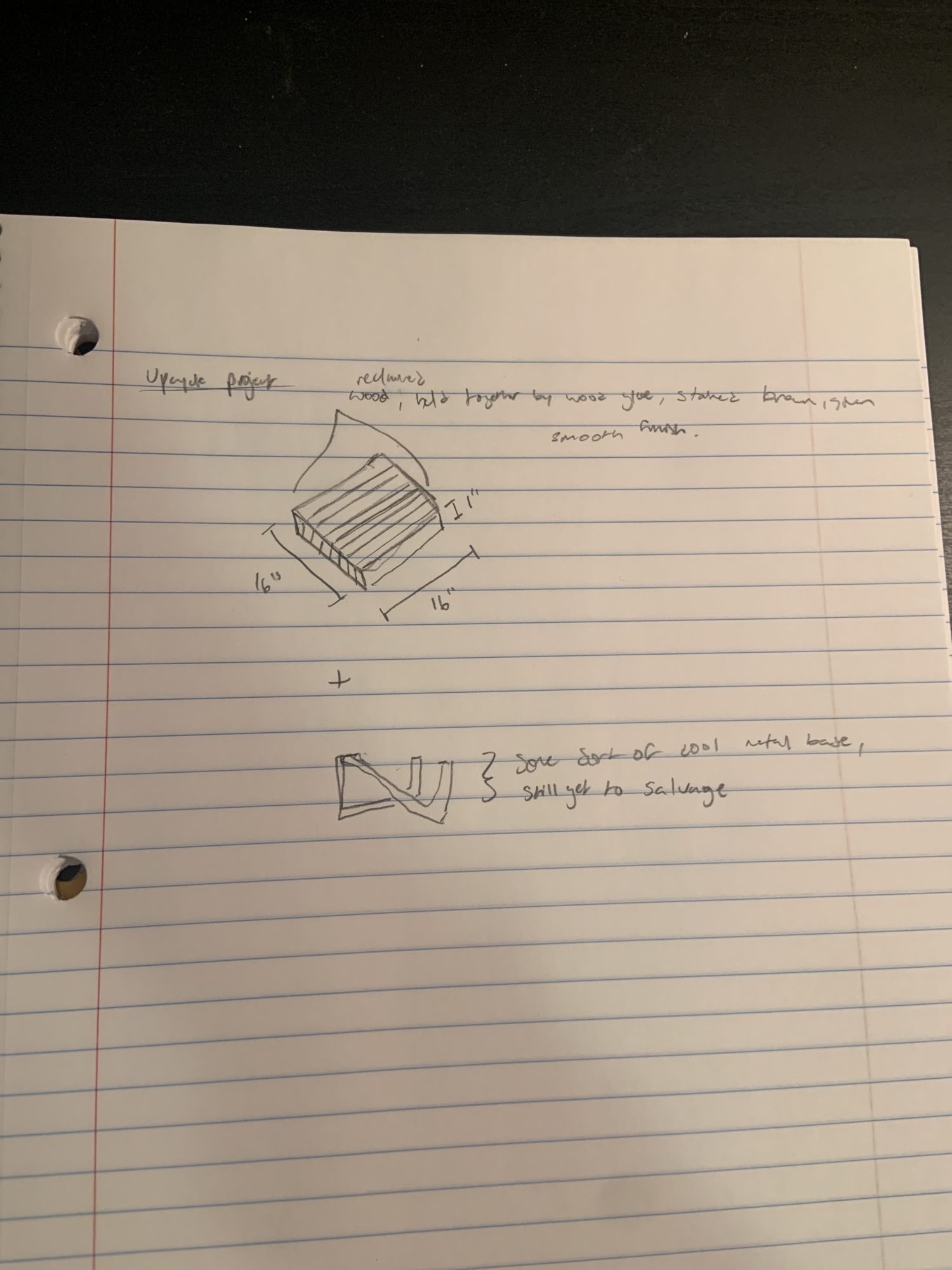
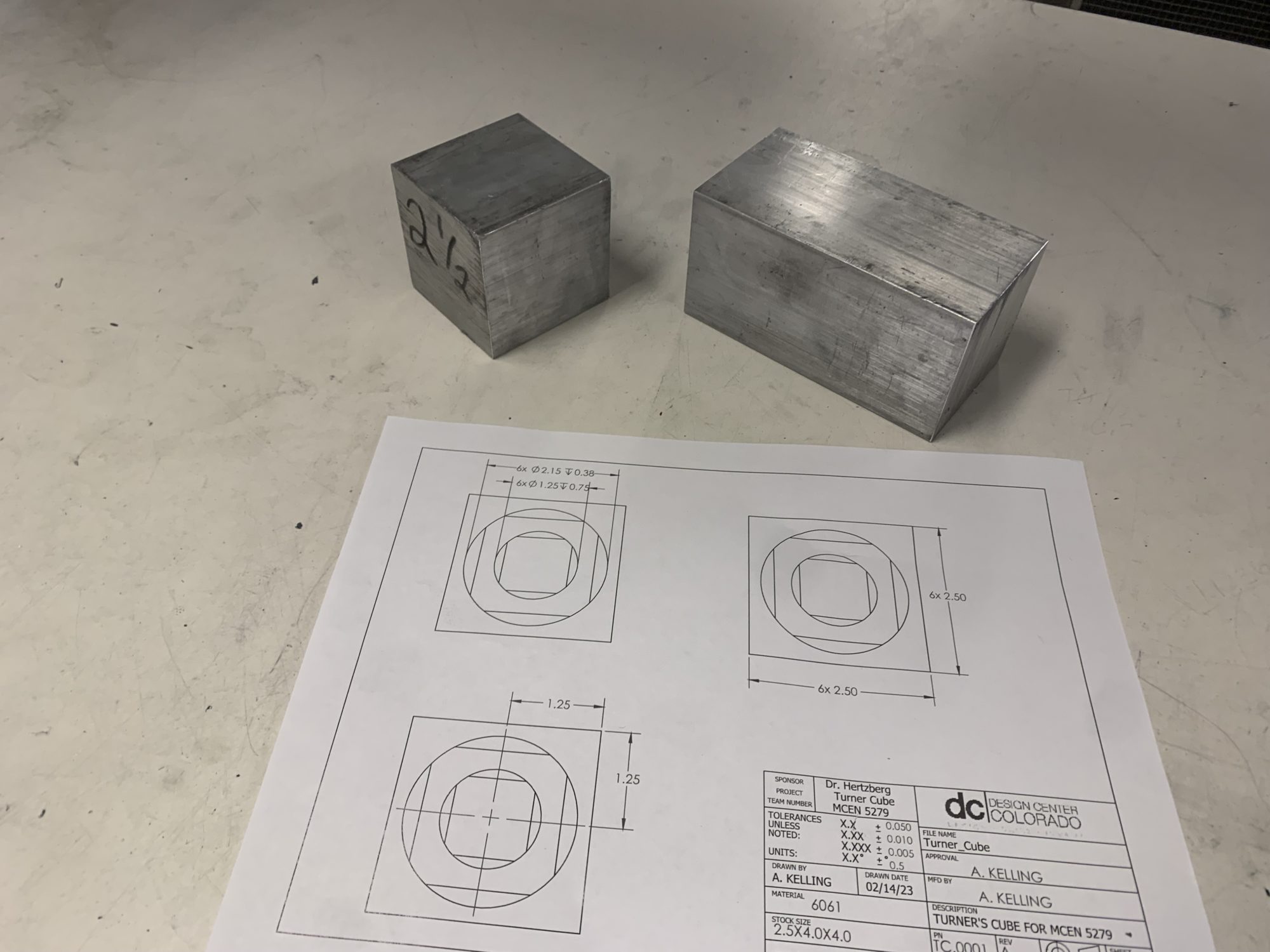
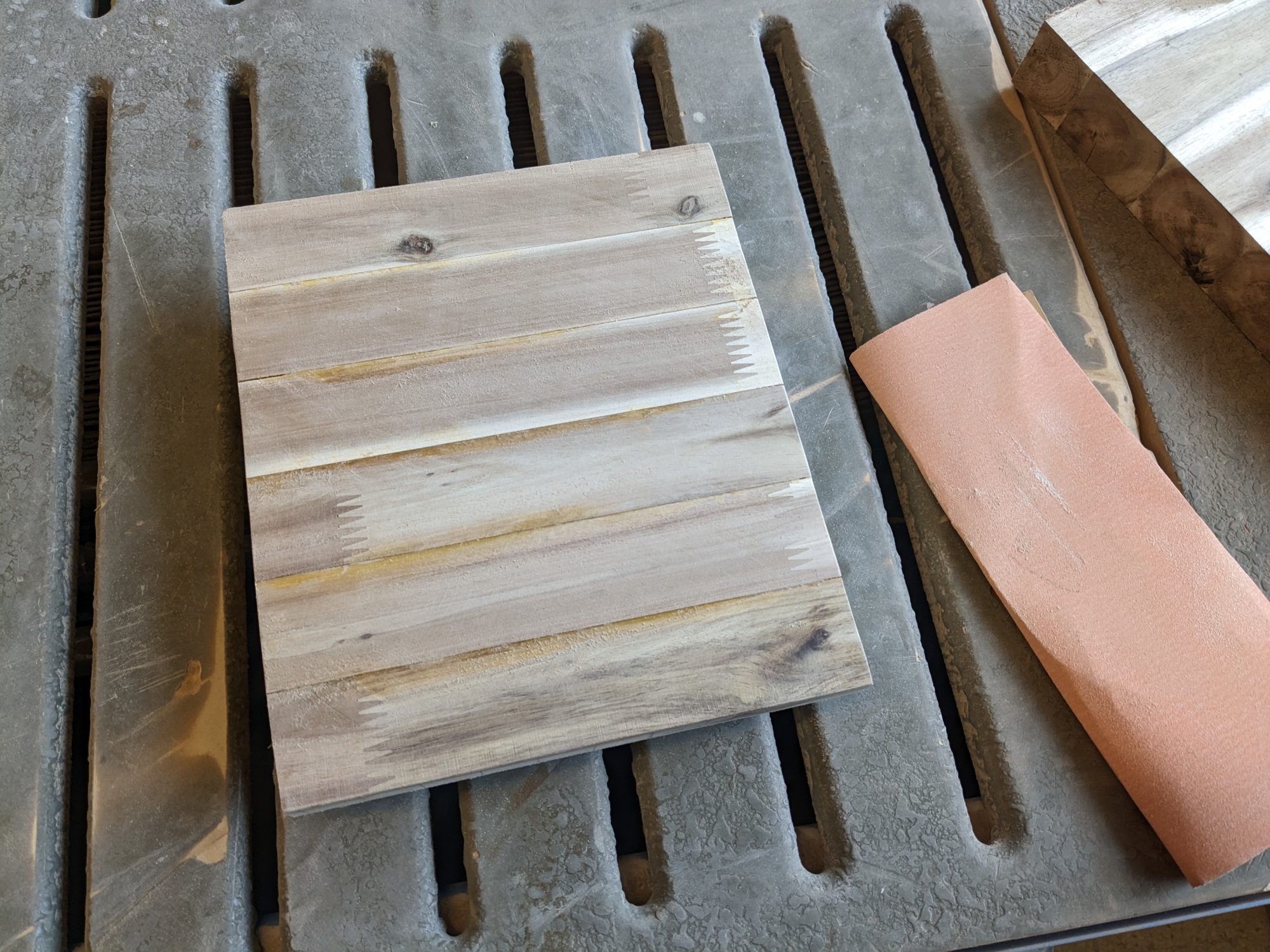
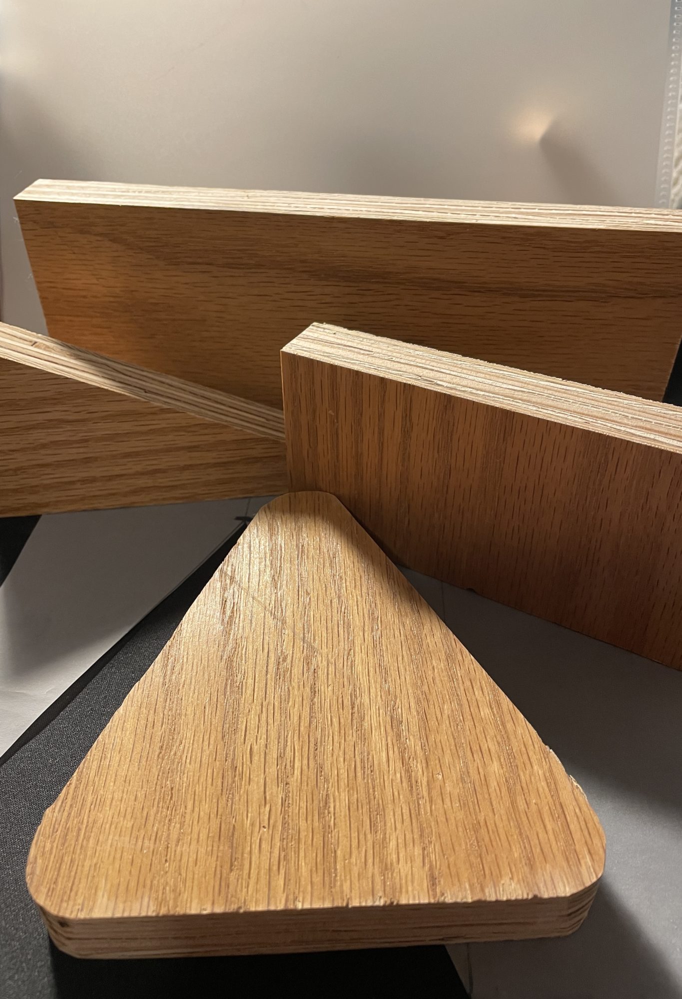
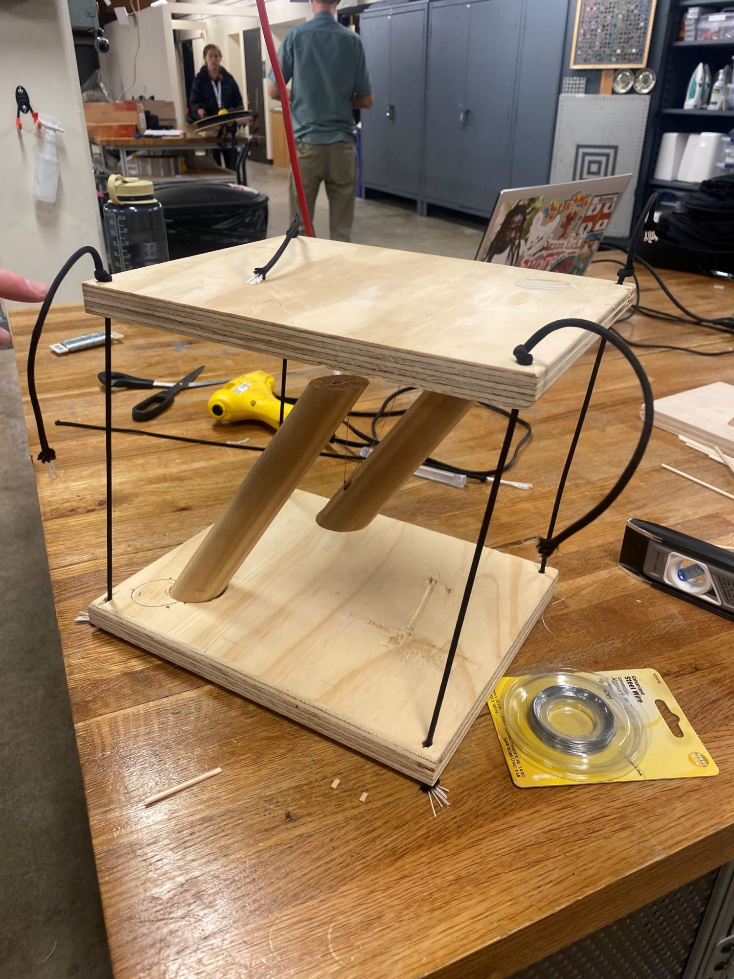
Tensegrity Table with Floating and Balance Aesthetic
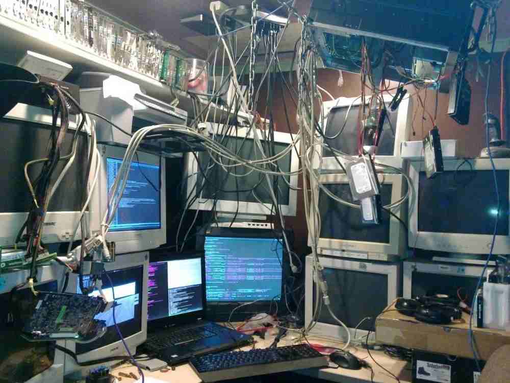
Cybernetic Punk, My Up-cycling Aesthetic
Upcycling Project Aesthetic: Mountain/ Rural/ Industrial
Aesthetic for Upcycle Project
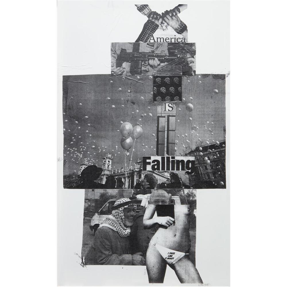
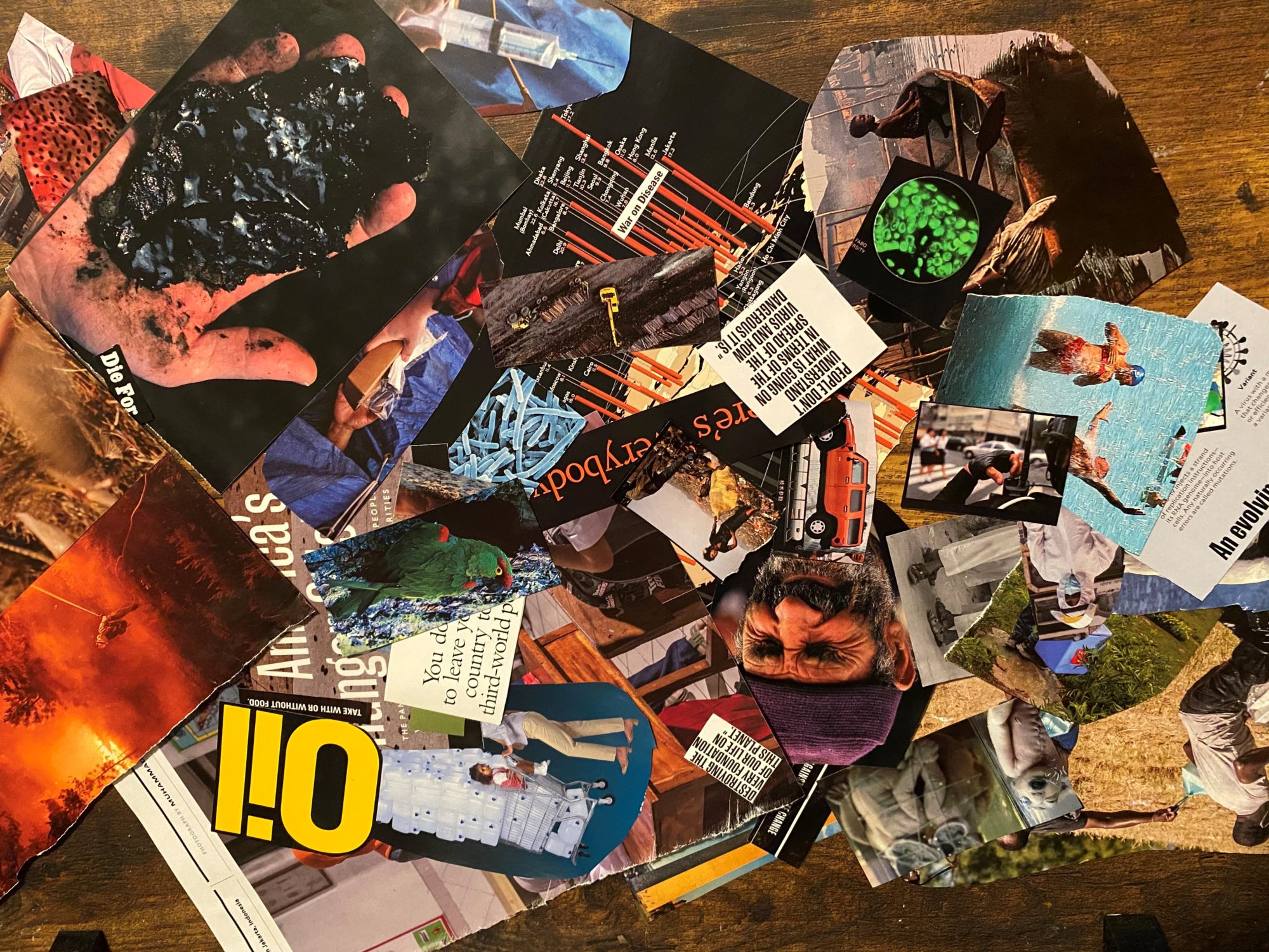
Upcycling Aesthetic // Dadaist Collage Featuring National Geographic
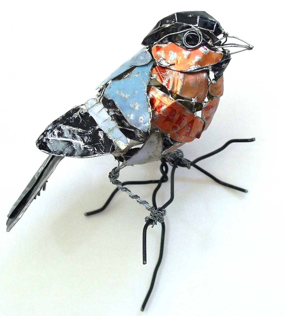
Upcycle Aesthetic: Imitating Nature
Upcycling Aesthetic
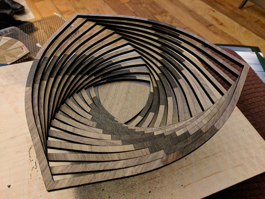
Upcycling Project Idea – Laser Cut Wall Plates
Upcycling Project – Minimalism
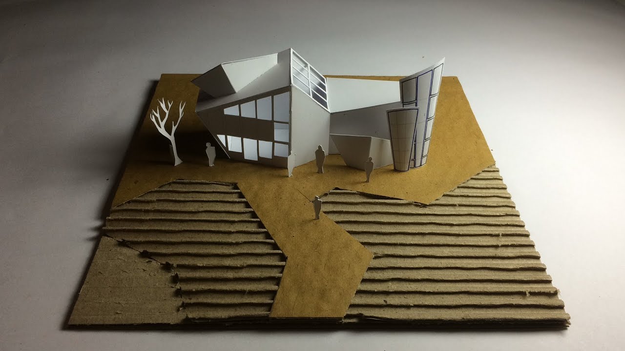
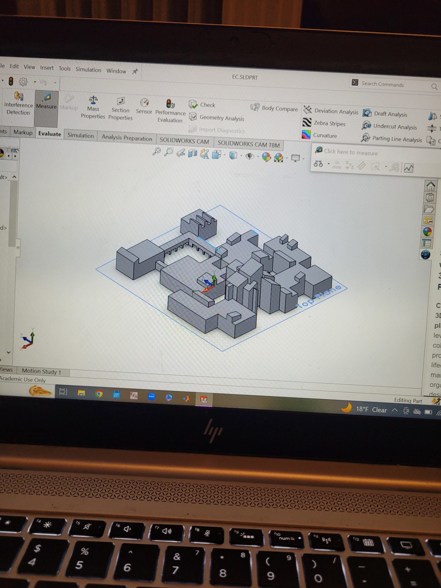
Upcycle Project Aesthetic : Contemporary Architecture Model
Upcycle Aesthetic – Desk Toy
Upcycling Aesthetic – Industrial Style
Upcycling Aesthetic – Nature Core
Upcycling Project Aesthetic – Minimalist Bike Fender
Upcycling Project Aesthetic
Upcycle Project Aesthetic: After Hours
Upcycling Aesthetic: Artificial Nature
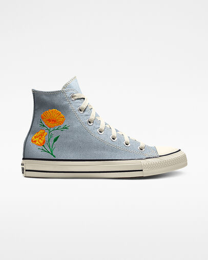
Upcycle Project Aesthetic: Floral Embroidery
Upcycling Project Aesthetic: Eldritch
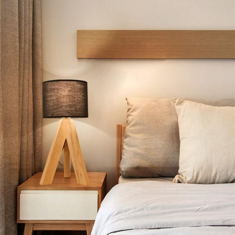
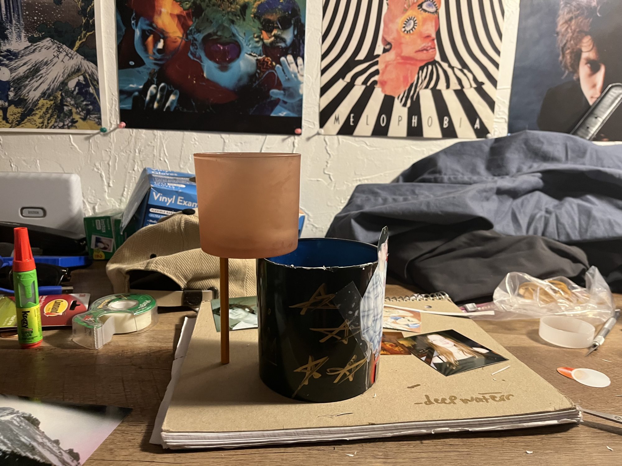
Upcycling Project: Minimalist desk/table light
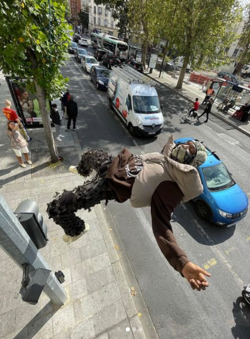
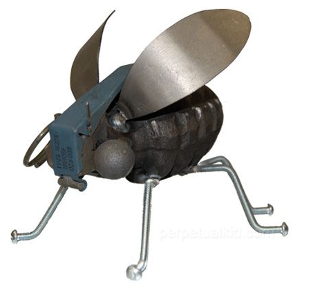
Upcycling Project Aesthetic: Grenade Moth
Upcycling Aesthetic – Contemporary Sculpture
Upcycling Project Aesthetic – PTFE Connectors
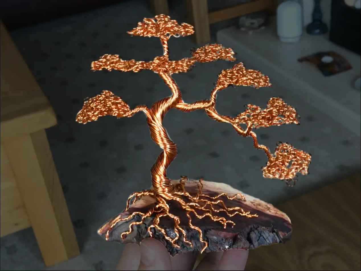
Upcycling Project Aesthetic – Twisted Wire Bonsai Tree
Upcycling – Succulent Garden
Upcycle Aesthetic
Upcycling Aesthetic: Pastoral
Biophilic Pencil Holder
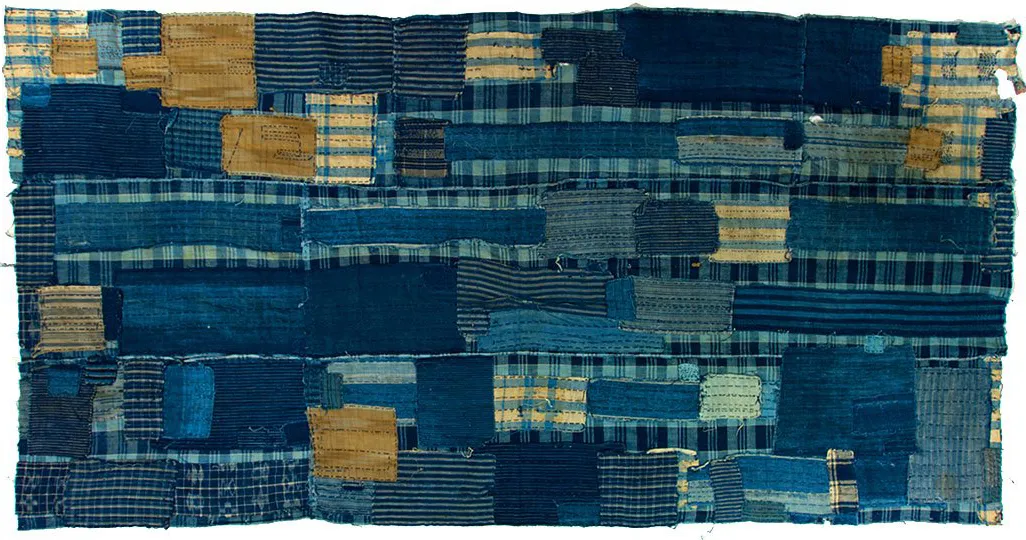
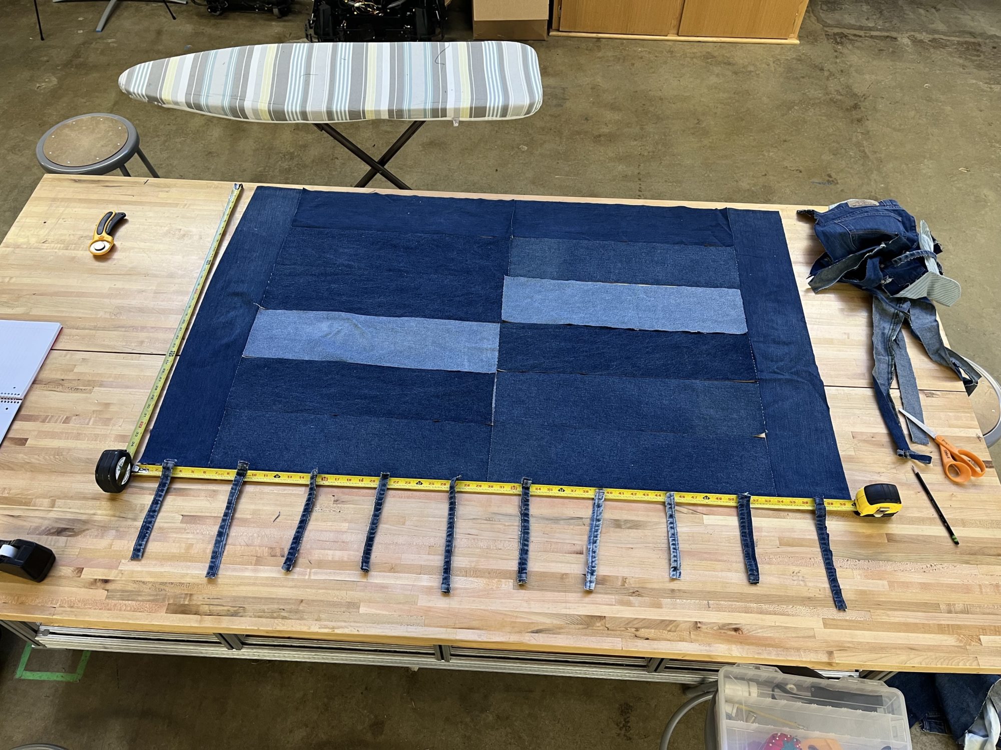
Japanese Boro Denim
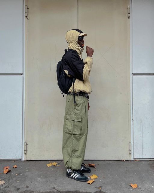
Y2K Cargo Aesthetic: Upcycling Project
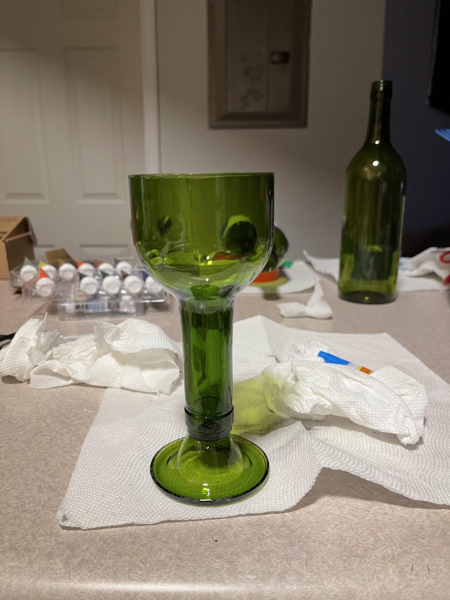
Upcycle Aesthetic – Rustic Uses of Wine Bottles
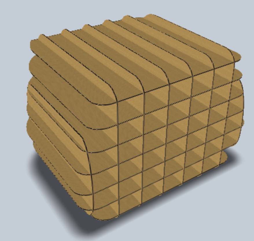
Biophilic Industrialism: Turning Wood into Mountains
Up-cycling Aesthetic :- Braided Wire Art.
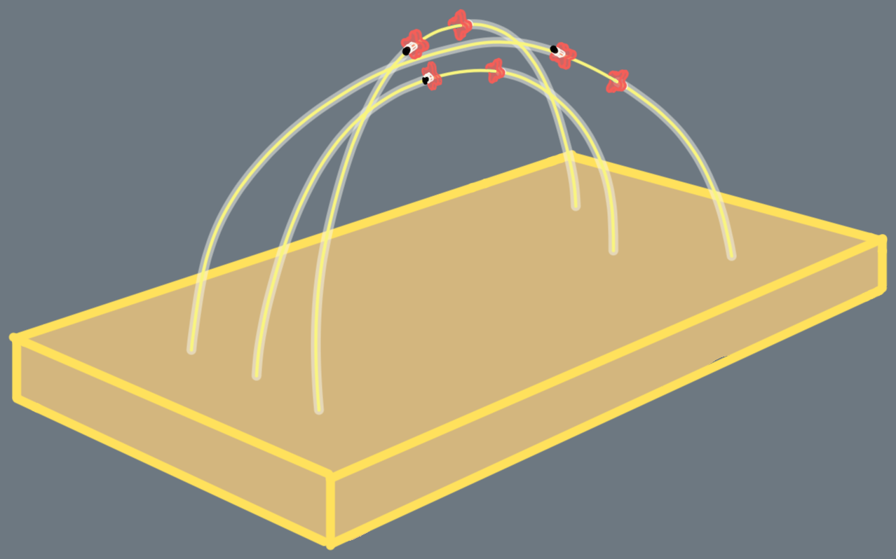
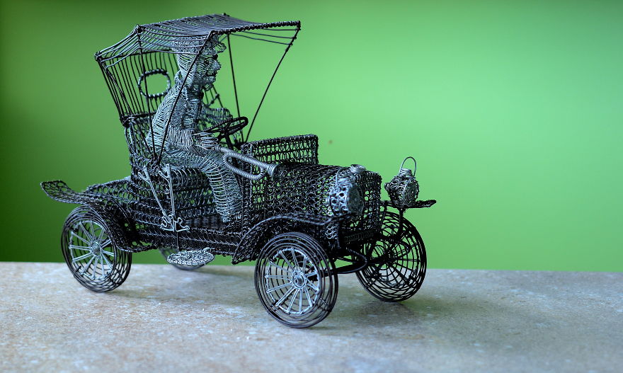
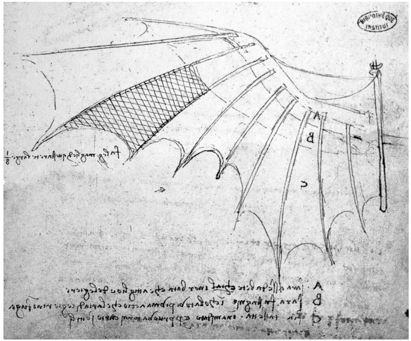
Upcycling Project Aesthetic – Articulated Wings
Upcycling Project Update 1
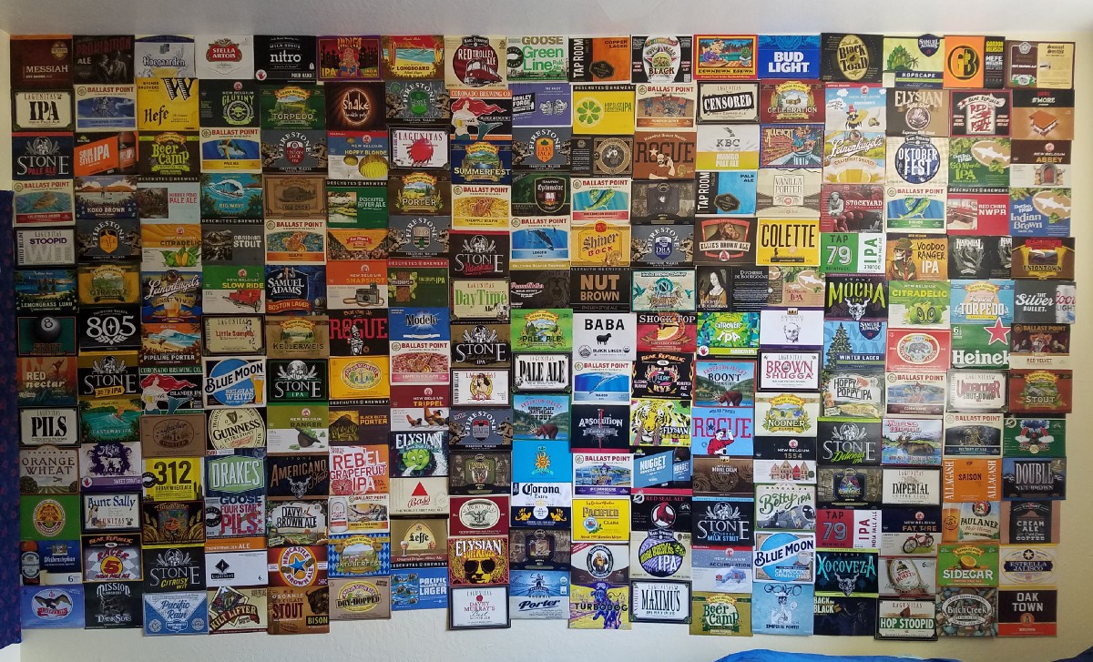
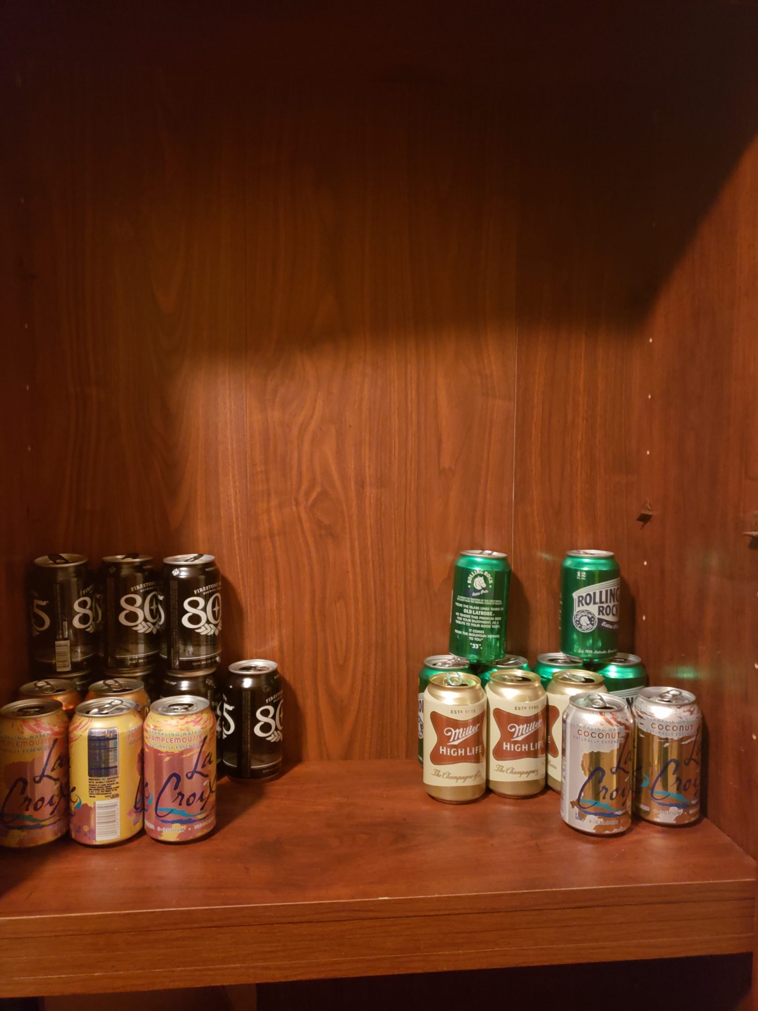
Upcycle Project Aesthetic: College Beer Wall
Upcycling Project – Cardboard Lantern
Upcycle Aesthetic: Central European Ornamentation
Upcycle Project Aesthetic
Upcycling Aesthetic
Upcycling Aesthetic: Layered Laser Cuts
Upcycling project aesthetic – Naturecore
Upcycle Progress – 70’s Cat House
Upcycling Aesthetic: Gorpcore
Upcycle Progress Report // Dadaism Collage Featuring Nat Geo
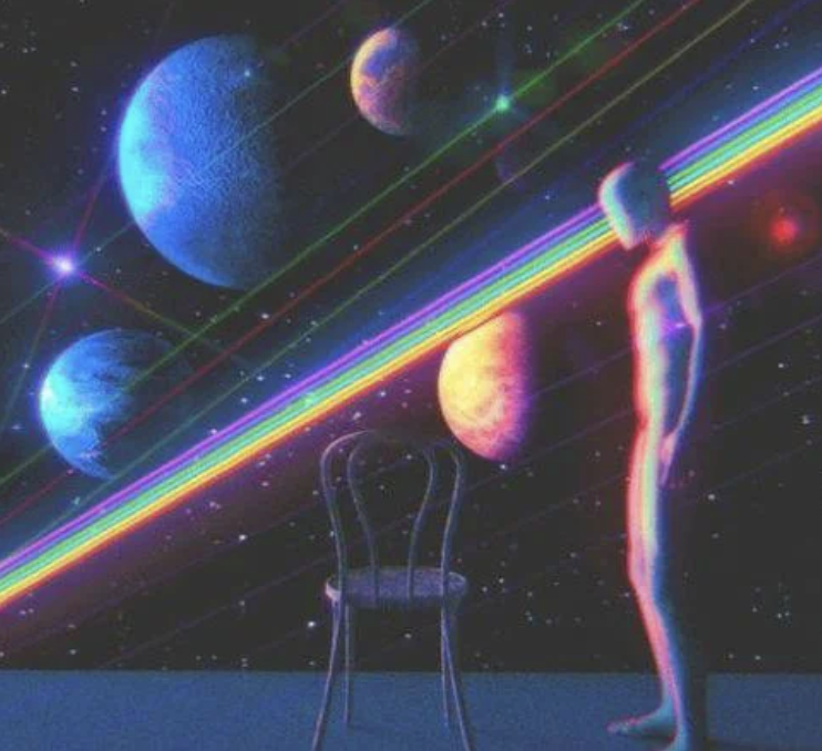
Upcycling Aesthetic: Spacecore
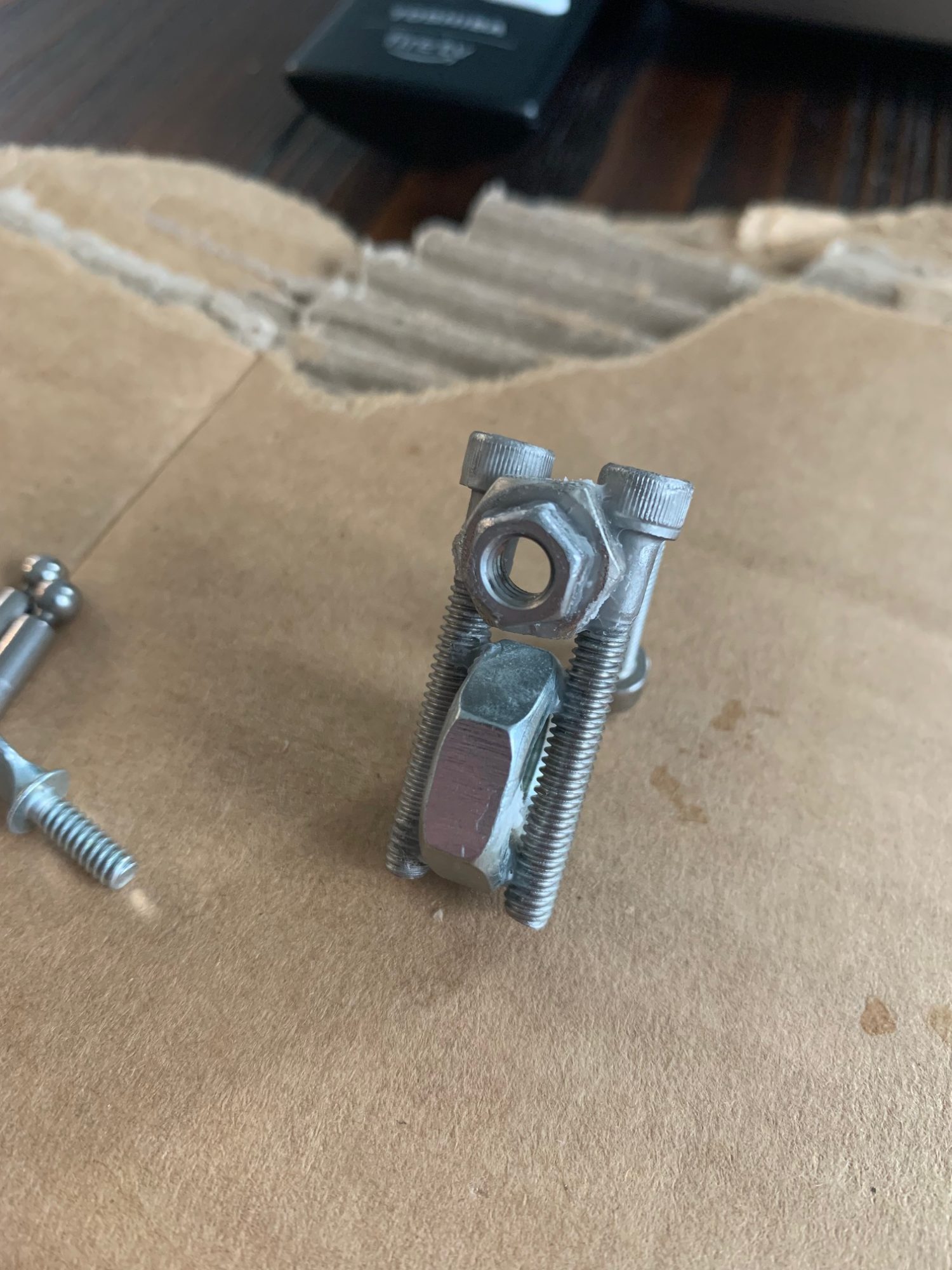
Upcycle Progress Report: Metal Motorcycle Paperweight
Upcycling Project Update
Upcycle Progress Report
Upcycle Update: Bioinspired Violin Picture Frame
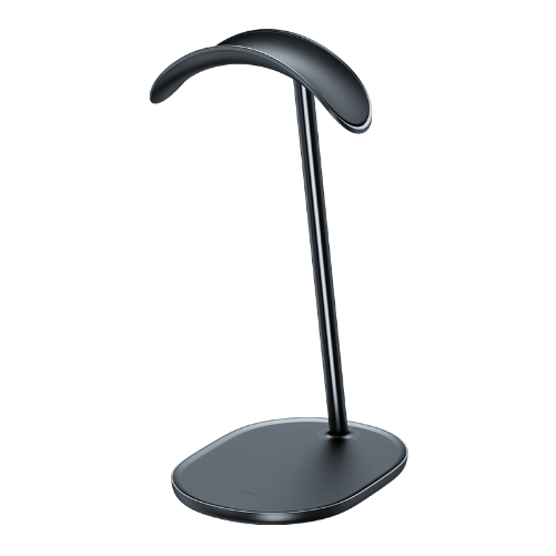
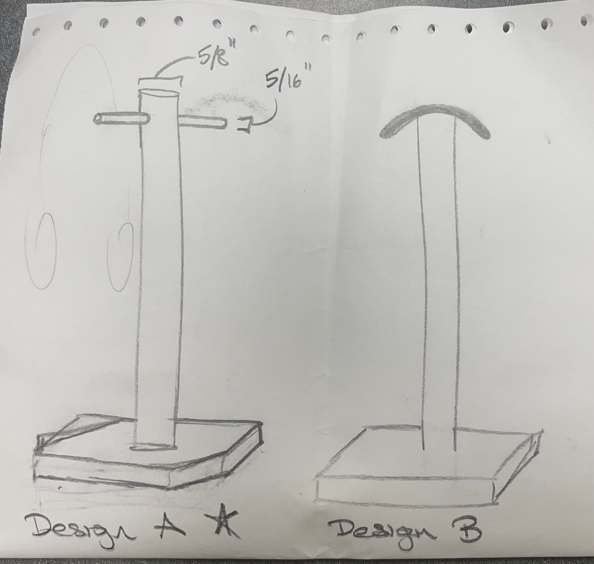
Upcycle Progress Report: Headphone Stand
Upcycle Progress Report
Upcycling Progress Report – Collage Planter
Boro Style Tapestry Progress
An Upcycling Progress Report
Upcycle Progress Report // Heider Iacometti
Post 3: Upcycle Progress Report
Upcycling Aesthetic – Organic Architecture
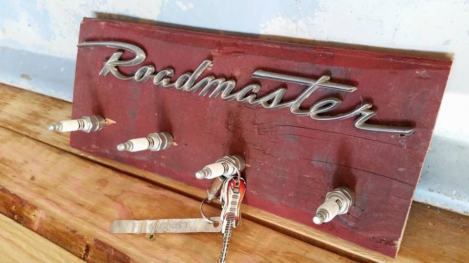
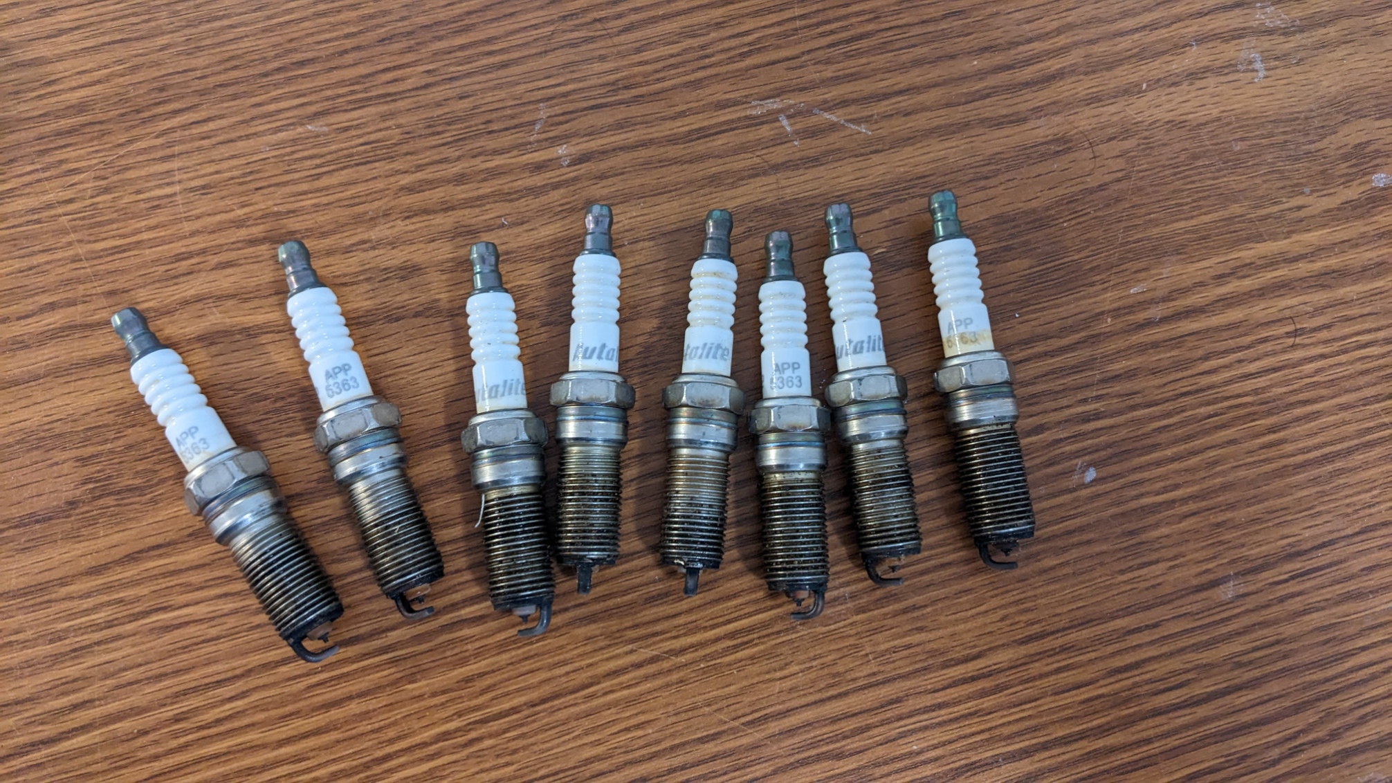
Spark plug wall hanger – Upcycle project progress
Up-cycling Progress Report
Minimalism Bike Fender Progress Report
Upcycled tobacco pouch progress report
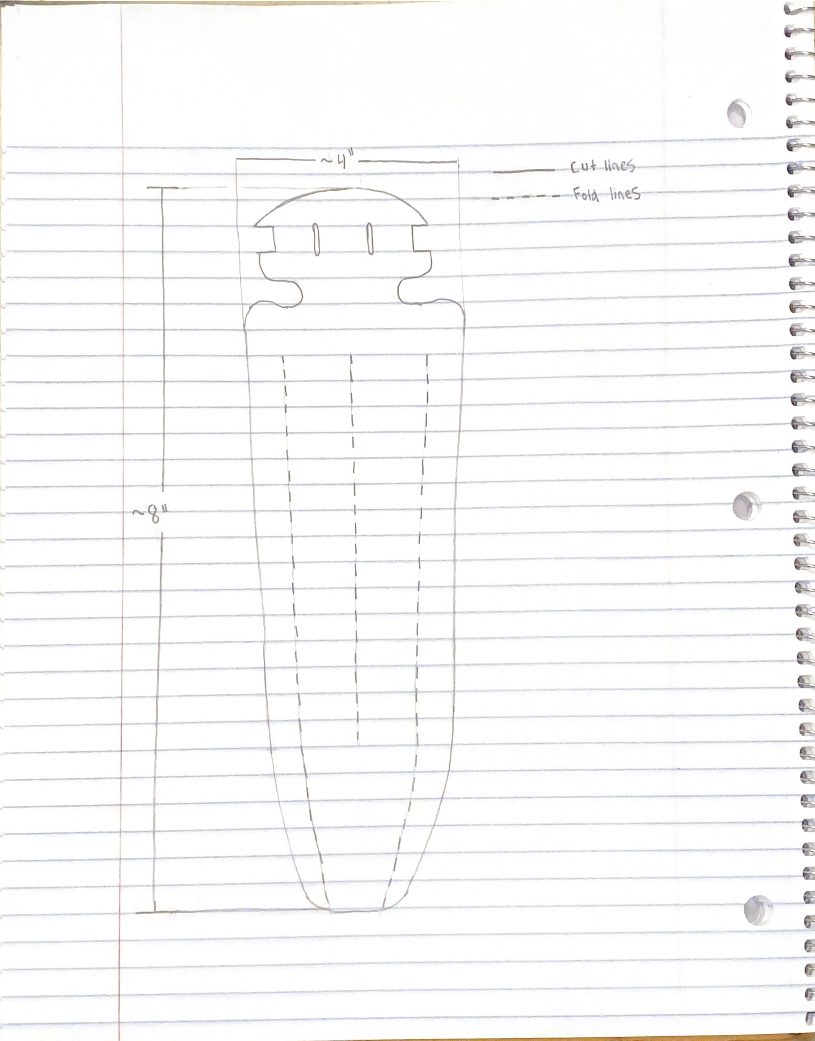
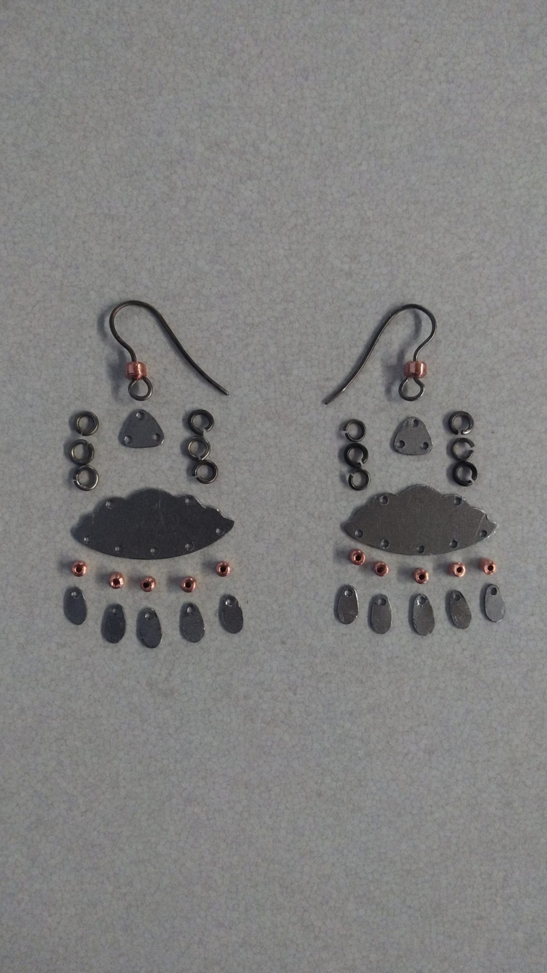
Upcycle Progress Report: Ornamented Earrings
Upcycle Progress : Contemporary Architecture Model
Upcycling Project Update – PTFE Sculpture
Upcycling Progress Report – Succulent Garden
Upcycle Progress Report – Keyboard Pixel Art
Upcycle Project Update: Artificial Nature
Upcycle Update – Desk Toy
Upcycling Progress Report
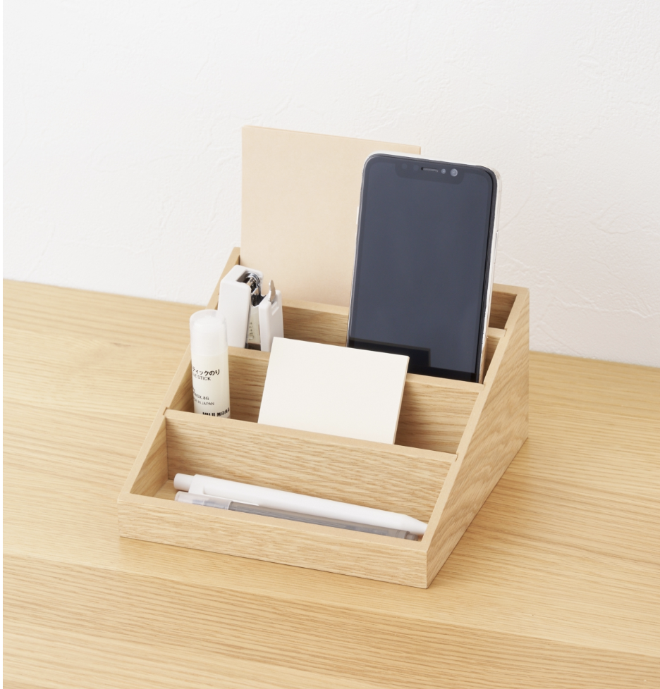
Upcycle Progress Update: Smartphone Stand
Tensegrity Table Update
1
2
3
4
5
Next
Menu