
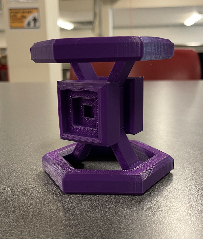
Above is a. picture of my final up-cyling product which I named: Miyadaiku Puzzle-like Sculpture. I found the design process and manufacturing of this project to be very fun and finally holding my final product was very rewarding! As a reminder, Miyadaiku is an ancient form of Japanese carpentry which aims to build structures without the use of fasteners of any kind: screws, glue, nails, etc. This is possible by strategically forming interfacing geometrical features between two parts. These can be in the form of a peg/hole, interlocking slots, opposing angles and more. This form of construction and it’s accompanying architecture is simple and elegant yet also extremely intricit as these structures must be specifically thought out and placed together like a puzzle.
In terms of inspiration, of course the majority of it stemmed from the Miyadaiku design process. Before even beginning my first sketch or deciding on a material, I began brainstorm the methods in which my piece would fit together. I wanted to incorporate the sharp clean lines of my aesthetic and most importantly implement absolutely no fasteners in it’s construction. This led to my initial vision of the structure. I began basing the overall silhouette on the shape of an hour glass and deciding on which components would interface and which would provide structure while keeping in mind how use the correct amount of parts so that the final product wasn’t too busy and yet not so simple that it was boring.
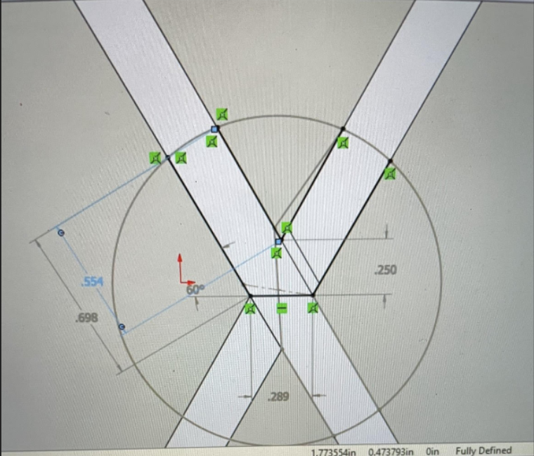
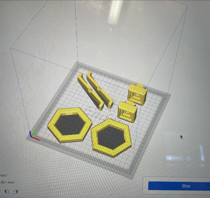
Below, I will step through the design and fabrication process more throughly using photos I took along the way. To start, I created a simple sketch which I presented in the previous progress post, this then progress into a Solidworks model with the end goal to be downloaded as an STL. file to be printed. With my MCEN background I have had a lot of experience in 3D modeling, that being said this was my first time working with interconnecting printed parts. This was definitely more of a challenge then I had initially thought for two reasons. First, to achieve my Miyadaiku goal, I needed my parts to interface with between a press and slip fit tolerance. The general rule of thumb here is to add or subtract .005 inches from interacting parts, or in my case the slots and pegs. While this is straightforward, there is also a “random” tolerance provided when actually printing parts based on one’s printer and printer quality. Because of this I had to use a guess and check method when modeling the different parts. Below is a screenshot I took when designing the cross bar portion of the sculpture and the layout I used when printing the final iteration.
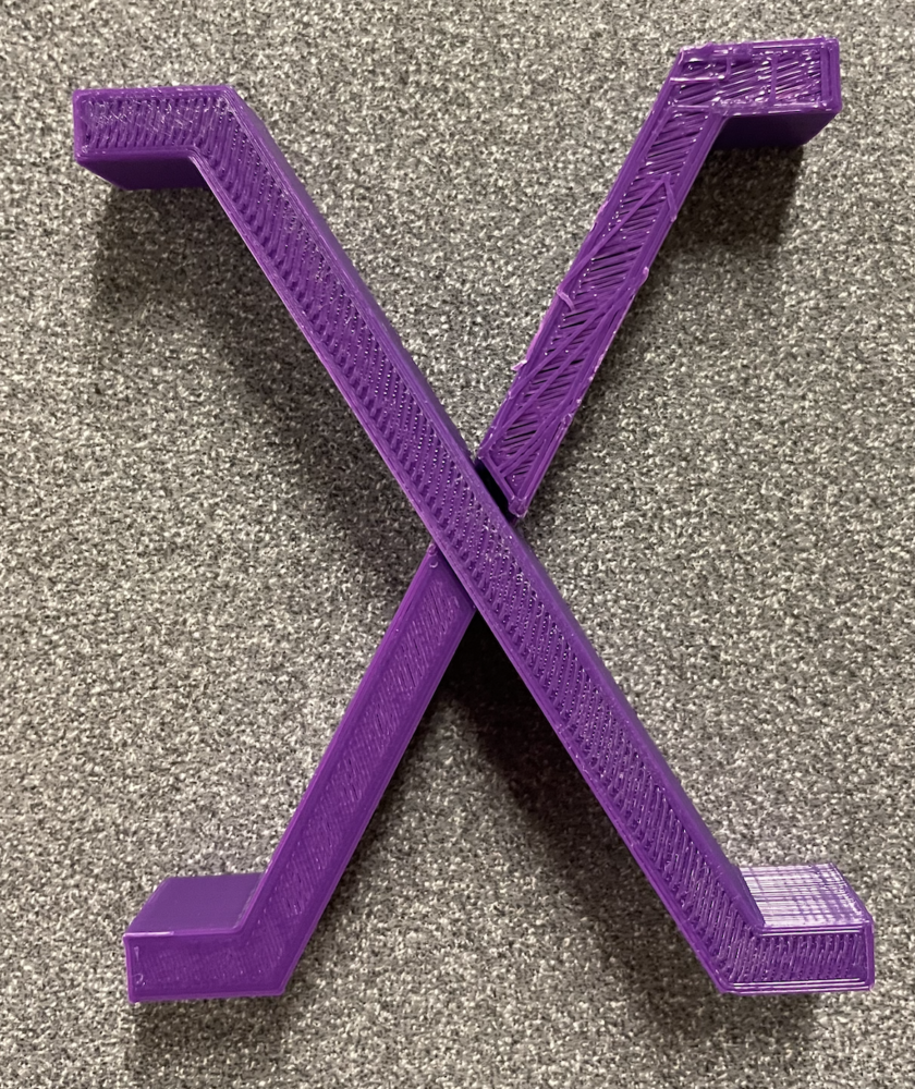
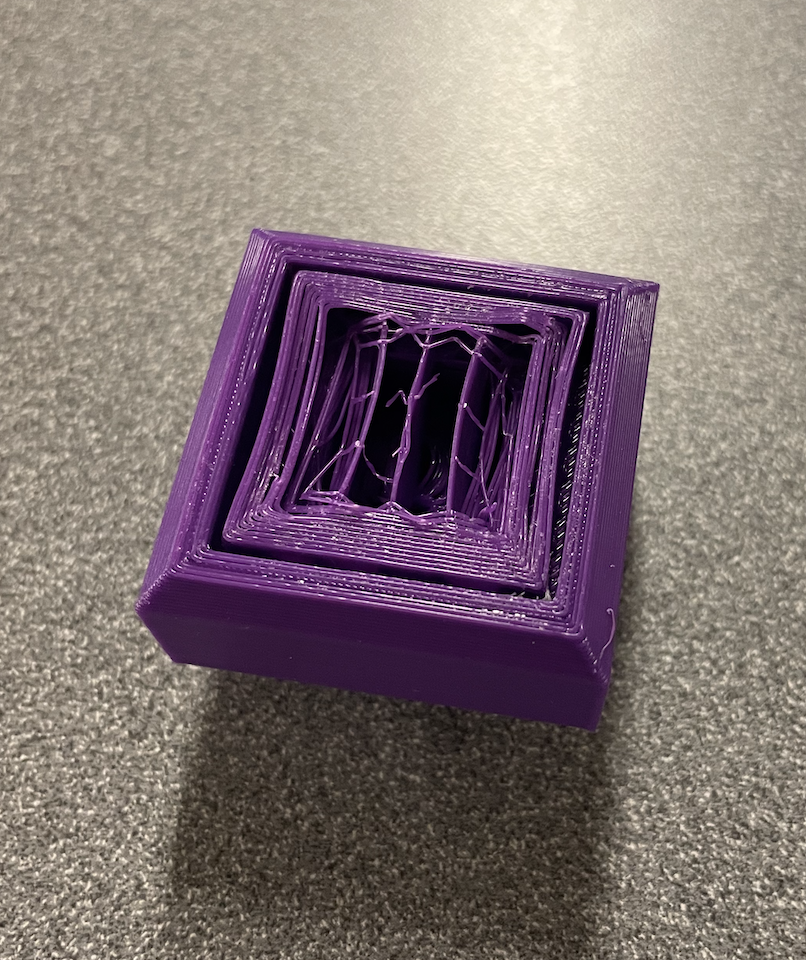
After printing the final version of all the parts, I began to assemble. If you take a look at the photo below, you can see a pretty sizable gap between the two pieces. This was a conscious decision made so that there would be enough flexure in these parts to then fit the bottom pegs of the bars into the base. However, when it actually came down to doing this, this gap was still a little small making assembly more difficult than expected.
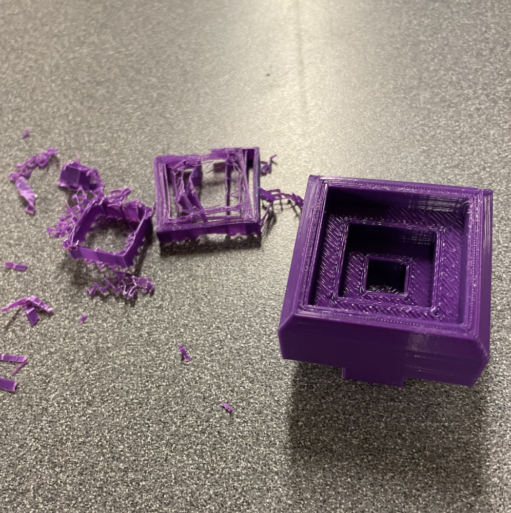
Another issue I encounter was when removing the print supports on a few parts. Due to the support infill being at too high of a percentage I was almost unable to remove it which would result in ugly extra material being stuck in the center piece of my sculpture. But, after about 10 minutes and some aggressive wire cutter and plier action I was able to seperate it away from the final piece.
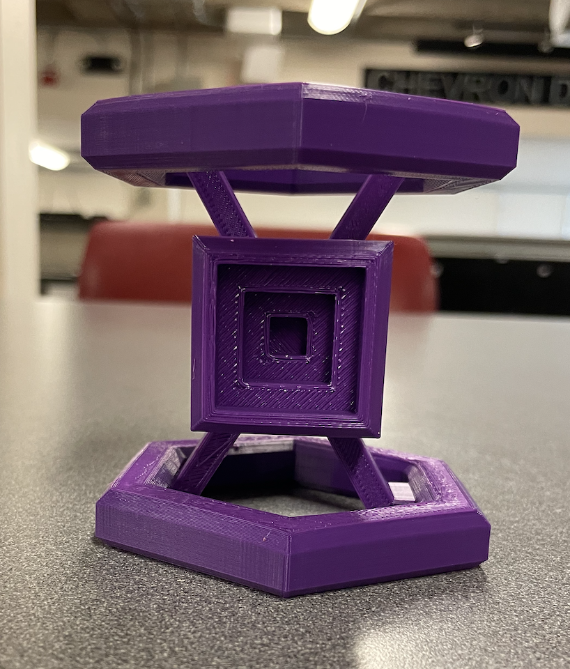
Once all support material was removed, it was smooth sailing and I was able to assemble the support structures together and finally place the center pieces on either side of it.
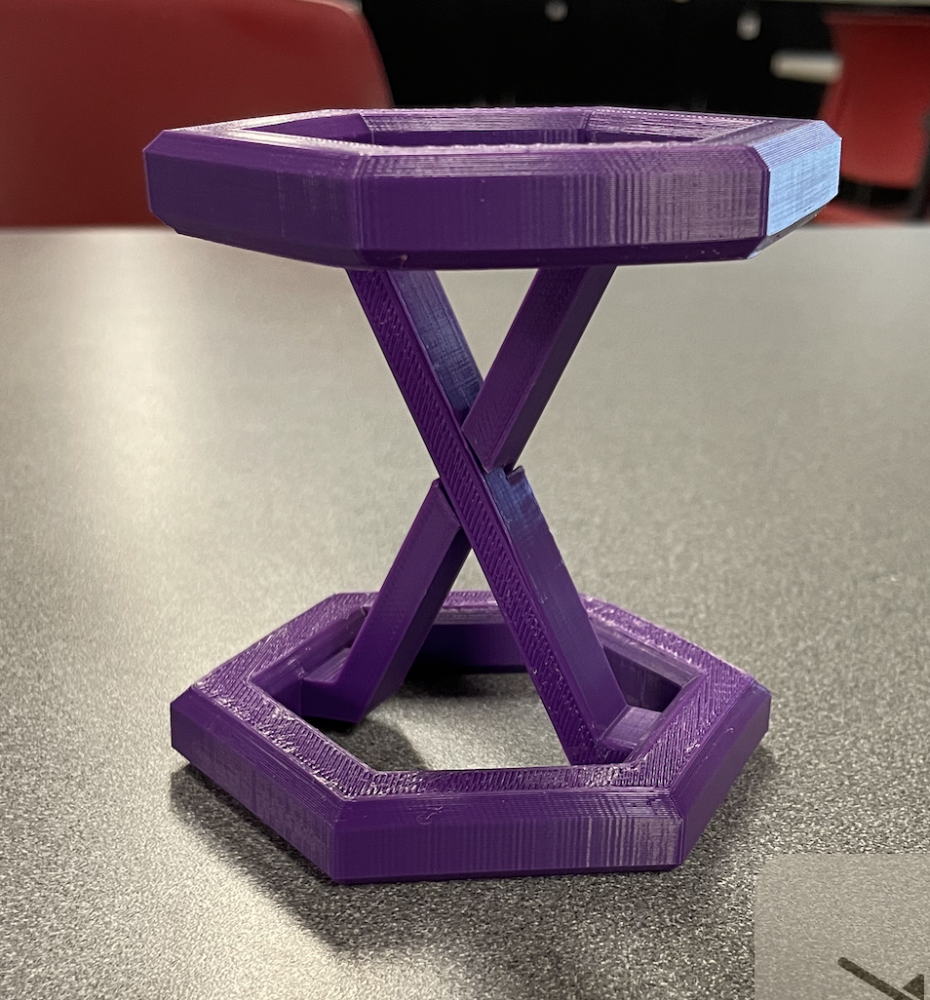
Below are a couple different shots of the final piece in different orientations and lighting. In the end I am happy with how it came out. I like the finish on the print and the overall structures shape and how the parts intertwine. The only negatives I have are as follows: First, for the up-cycle aspect of this project, I intended to use a bunch of almost spent spools of 3D printing filament spliced together with the intension to utilize filament that would be thrown away anyway. Unfortunately, I was unable to acquire the number of spools necessary to do so. After realizing this, my second best option was to go to the ITL in the engineering center and ask what their oldest spool of filament was and what was consistently not being used. For whatever reason, the purple filament that I ended using had been sitting at the ITL buried away because no one liked the color. So, I decided to give it a purpose in my design project. The second issue I had with my final product was it’s end size which I will talk more on later. Unfortunately it is very hard to truly gauge the size of a 3D model on a screen when you can simple zoom in and out as needed so my sculpture was smaller then I intended.
As I described above, the final sculpture came out smaller then I had expect. I had initially intended this piece to be used as a stand for use as either a plant holder, laptop stand etc. Standing at around 3 by 4 inches it likely will not be able to hold the weight of these objects. Still, I can place smaller objects on it and use it as a stand for small tools which I will do so in my house, providing it with lasting functionality. On the artistic side, I really liked designing with the Miyadaiku methods in mind and using Solidworks for art rather then utility. It was a really cool process unlike what I usually do in classes, designing for strength and functionally requirements rather then aesthetic.
If I were to repeat this project again, I would construct my sculpture larger to increase it’s utility and I would also make it out of wood as I initially intended to. This would require more time and wood working experience but, the final product would look more finished and presentable as a piece of furniture.
4 Comments. Leave new
Hi Max, very cool project I really like the color you chose. I found it interesting that you made it in many different parts. How did you tolerance these parts in cad to ensure they would fit correctly? Overall great job
Hi Jarod, thank you for reading my post and for the kind words! In terms of tolerancing I used +.005 inches to interacting parts which its the generally accepted slip fit tolerance for 3D printed parts. That being said, due to the quality of my printer this wasn’t super accurate so I increased this tolerance up to closer to .015 inches.
Hi Max, I think this is a very cool project and the final product looks super nice! I really like the color choice and the overall design. How long did it take you to design and model it in Solidworks?
Hi Ari, thank you for reading my post and for the kind words! The design came to me sort of quickly and I sketched it within a hour. In terms of Solidworks though, getting the tolerances to match up, making sure I would actually be able to assemble the prints and making something that resembled the sketch probably took closer to 3 hours.