
INTRODUCTION:
This is the first part of my final report blog, and it will cover my inspiration behind the design, explain the aesthetics in greater detail, walk through the dynamic components of the spider toy’s drive train, fabrication of the overall design, and the mishaps that happened along the way. The purpose of this report is to explain my own design process, and possibly reduce the necessary head aches needed to build your own wind up toy.
INITIAL CONCEPT & INSPIRATION:
The original idea was to design and fabricate a “cute or horrifying wind-up spider toy” that could use some sort of hydraulic system to move. My goal was to bio-mimic the movements of a real spider. This was my top constraint and the idea never left the drawing board, because the hydraulic system just was not feasible for lack of time and resources. Next I wanted to move onto a design that could be easily fabricated and taken apart. Since if there were any issues with my toy’s design, I could quickly troubleshoot my issues by disassembling its structural walls in order to get into the moving components. At this time, the project pivoted towards a simpler hand powered toy that could have aesthetics incorporated on top of it like a shell. I got the approach from looking up videos and schematics on how toys were made in China, and by visiting some local toy stores for inspiration too.
A lot of different thoughts and styles were considered for the aesthetics of this project. I decided earlier in the semester that my spider toy would follow the hypothetical uncanny valley cart for aesthetic design. The goal was to make either a cute, plush toy that anybody would want to play with and hold, like a stuff animal. Or a spider toy that falls right into the uncanny valley, and looked liked it came right out of the gates of hell.
DRIVE TRAIN:
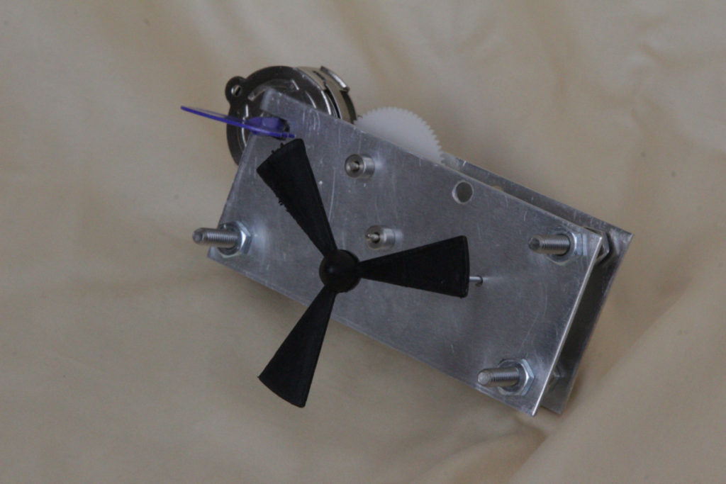
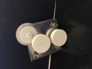
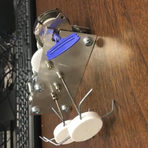
The skeleton of the wind up spider toy. The whole system is driven by turning the blue faucet key.
The wind up toy skeleton ran by turning the wind up toy in the counter-clockwise direction, then releasing it onto a table to make the spider toy “walk”. The drive train (Figure #1) operates by compressing the horizontal torque spring (2) with the rotating action of the faucet key (1). The horizontal spring is attached to the body’s frame at the outer end of the spiral (3), and a rod is connected to the inner end of the spiral to main gear (4). When the applied torque to compressed spring is released by the operator, the drive train rotates the another gear connected through a shaft to wheels (6).
Figure #1: Demonstrates how the basic mechanism for a “wind up toy” system works.
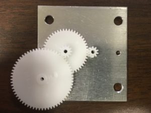
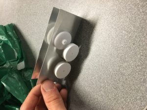
The photo above shows three plastic gears meshed together on one of the prototype wind up toy blanks.
The entire wind up spider toy has a total of 5 gears to transfer power from the torque spring to the wheels. I managed to purchased a toy with the necessary spring mechanism and gear teeth ratio to mesh with the solar power car gears axle wheel, this was vital to the smooth operation of the car. A small plastic gear was added in between the gear axle wheels to help with clearance and to ensure the wheels rotate in the same direction.
AESTHETICS:

I decided at the beginning of this project that I wanted to build a toy that followed the uncanny valley chart of aesthetic design. Specifically I wanted to stay in the “cute teddy bear zone” or the “zombie zone” of the chart, because I wanted my toy to either be really lovable like a kitten or so horrifying that you wanted to scream and yell, “KILL IT WITH FIRE”. I took a lot of inspiration from monster movie makeup, because the creatures looks extremely lifelike The decision was made to use clay molding, silicon casting, and plastic casting materials (similar to those used in the guest lecture on clay modeling), because multiple spider shell molds can be fabricated and reproduced at a faster and more reliable pace than 3-D printers. Then once the final plastic molds are made I can simply paint different types of latex, and acrylic on the spider shell to create the aesthetic. This process allows for greater flexibility with the colors, textures, and features (ears, eyes, limbs, fake hair) of the design.
FABRICATION:
My goal for this final project was to use my skills in machining do as much as fabrication as possible in the ITLL machine shop. I wanted to do this in order to gain additional experience with design for manufacturing, and improve my skills with the CNC mills and other technical machinery.
Wind Up Toy:
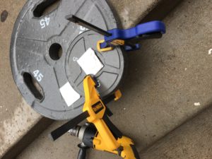
The start to my fabrication process began with prototyping my design at home. Here is a photo me drilling into some aluminium sheet squares to make my prototypes, and test the plastic gears I took from another device.

I drilled out the holes in the aluminum sheet using a CNC mill for accuracy and tolerance, then used the sheet metal bender to get decent 90 degree angles. Here I used again 22 Ga aluminum sheets. The sheet metal was bent into a U-shape, so I wouldn’t have to use fasteners. But this became a major issue when I tried to put the gears on.
This is a photo of my first design iteration. The gear on the side is what I used to make the wheels turn. (Yay! My project kind of works!) There is a lot of friction in the drive train, so I need to do some trouble shooting.
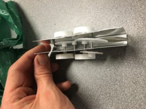
A photo to give you a visual of the inside. The spring hasn’t been added yet, so its a manual turn system at the moment. The aluminum sheet was causing me a lot of tension, so I need to move up to a thick gauge of aluminum sheet.
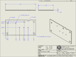
Here is the CAD drawings for the wind up toy plates. The holes correspond to the position of the gear centers, and fasteners.

Here is the second iteration of my design, and these holes needed to be CAD so the tiny tolerances of the plastic gear teeth can mesh up properly. The square blanks are still made out 16 Ga aluminum sheet metal, and they were cut to size by the sheet metal bender.
Here is the completed version of my second iteration. I ended up cutting these blanks to small on accident, so there was interference with the wheels and no room for the torque spring component. Had to re-fabricate the aluminum blanks a third time.
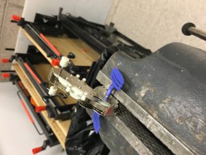
Photo of the le pinch toy before it was taken apart. I was trying to salvage the blue key and the spring mechanism attached to it.
I forgot to take photo graphs of the 3rd iteration and final design process, but essentially the building process was the exact same. I cut larger aluminum blanks (2″ by 4″) using the sheet metal cutter again, because that machine takes less time and is more accurate than the band saw. Used the same 3-axis CNC mill to drill out the holes and milled a slot for the wind up toy gear/spring. The wind up toy was one single component that could not be taken apart, so it had to be slid and then fastened down to ensure it meshed with the axle wheel gears properly. Then the entire wind up toy was fastened together the 10-32″ Phillips screw and nuts. To my machinist friends I used Phillip head machine screws over cap head machine screws, because the Phillips threaded along its entire length, the while the cap head did not which caused slack and friction which made the gear system jam up.

This is a photo of my wind up toy at the ITLL Design Expo. Photo Credit: Jean Hertzberg
Spider Shell:

On the left side of the photo is the Urethane Mold Rubber Mix, which I will use to make the rubber spider shell cast model. On the right side of the photo is the red brick clay that will be hand modeled to look like a spider, then the rubber liquid mix will pour over the spider. Not including the time it takes to model a spider in clay, the urethane takes up 16 hours to set fully.
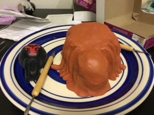
On the left is a wind up toy spider that used as a template when shaping my own spider out of the clay. This clay modeling is a lot harder than I originally anticipated, because my artistic skills have taken a dive since I felt a lot of my art classes in high school.
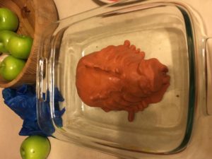
Here is the finished spider clay model that is ready to be molded! The spider has eight legs, two eyes, a single jaw, and two column of spikes down its back, since the photo is a little hard to see. I put the clay spider in a glass jar, because I wanted to easily peel away the silicon when everything set.
Unfortunately, the product has a huge warning label explaining how death is a high possibility if you use this product in a closed room. This was during the three weeks we had snow and rain, so I could not start my aesthetics any sooner. The aesthetics never got fully built, because I ran out of time.
SPECS:
Project’s Total Weight: ~0.8 lbs
Quantity – Part Name [Controllable Dimensions]:
- 2 – medium sized plastic gears
- 1 – small sized plastic gear
- 1 – “le pinch” wind up toy spring
- 2 – 16 Ga Aluminum Sheets [2″ by 4″]
- 2 – steel leg rods [4″ length]
- 2 – gear rods [2″ length]
- 4 – 10-32″ Phillip head screws – 1″ length
- 12 – 10-32″ nuts
- 8 – 3/32″ Plated Brass Dura-Collars
Bill of Materials:
The overall design was less expensive then originally anticipated. This semester I did not have to buy any textbooks, so I decided to dedicate about $200 to this project. Since the wind up spider toy was extremely small, and made out of common materials the overall costs were pretty cheap. Also, the wind up spider toy would have been even cheaper if I did not have to “cannibalism” other toys for necessary parts.
Here are a list of my expenditures that were used in the wind up spider toy project. This does not include replacement parts or the prototypes, just the final design and the money spent on aesthetics for the last part of the design.
Store Bought Name – Dollar Amount ($) – Purchased From:
- Solar Powered Car — $7.25 — McGunkins
- Solar Wind Turbine Set — $8.86 — McGunkins
- Wire — $0.00 — ITLL
- 10-32 Fasteners and Nuts — $0.00 — Idea Forge
- Le Pinch Wind Up Toy — $15.50 — Into The Wind
- Polymer clay, Kato Polyclay, brown (1 lb) — $16.60 — Meininger
- Smooth-On Reoflex 30 Urethane Mold Rubber Mix, Shore 30A Hardness, No Degassing — $24.50 — Meininger
- 3/32″ Plated Brass Dura-Collars, Complete with Allen Wrench — $3.96 — McGunkins
Total: $76.67
FINAL DESIGN:
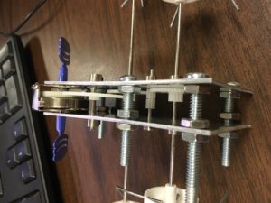
Wind Up Toy Skeleton
This is my final wind up spider toy design shown above, this wheels were added during the presentation week to show that the design could move. But the wind up toy did not run as smoothly as I was hoping it would be, because the toy still had a lot of friction, some gear meshing issues, and jamming problems that were causing the toy to cease function. I think designing the plate to better accommodate the salvaged blue key spring mechanism in a more rigid structure would fix this issue almost entirely. But I was able to demonstrate a functioning wind up toy, even though it does not look anything like a spider. I think the reason is, I took too long deciding the spider shells method of fabrication, and then some bad weather delayed my chances of making the spider shell before the ITLL Design Expo. I am satisfied that the wind up toy skeleton does emulate the industrial aesthetic with lots of fasteners, shiny metal, angled geometry, and minimal style.
4 Comments. Leave new
It sucks that you couldn’t finish the project, but it still looks like you put a lot of work into it. The gears, the wires, the machined parts… everything was intricate and pretty well thought out. Once you’re finished, I bet it’ll be a hoot to play with!
It was very interesting hearing about your creative process and the challenges you faced, it sounds like the experience was very educational and you got a lot out of all your problem-solving. What would you like to do next with this project? Will you continue to work on the project into the future?
I am still fascinated by the gears. I still think you should glue a giant spider to the top =)
You can tell that you put a lot of thought into this, good work!