
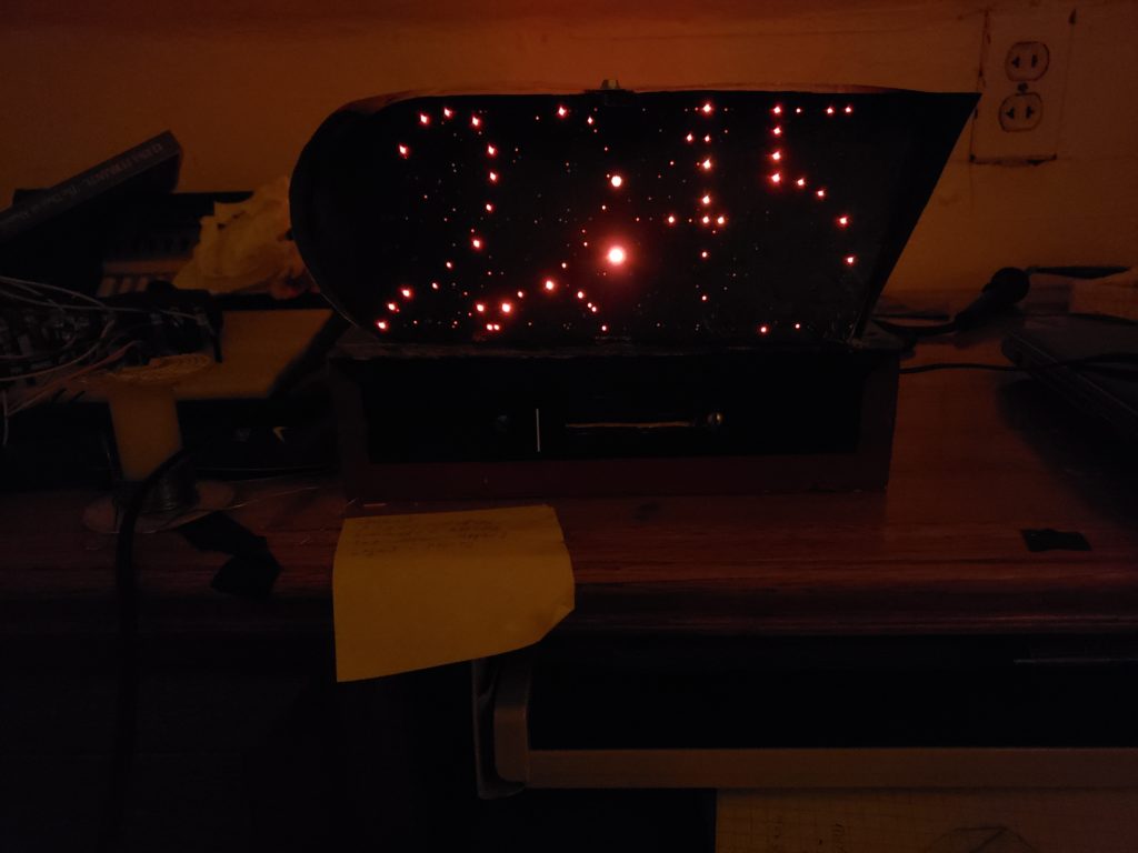
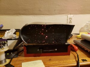
For my main project, I designed and built a digital clock where the letters were created using fiber optic cabled inlaid into black epoxy resin. The purpose of this was to create the illusion of the numbers being like constellations in the night sky. Additionally, I chose to apply the aesthetic of Italian Futurism to the artifact. I chose this aesthetic because of how impactful it was on subsequent design movements in the 20th century and my unfamiliarity with the aesthetic provided a unique opportunity to learn about a new design movement. The final product can be seen in the featured image.
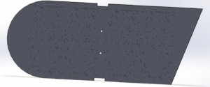
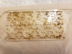
The design and building of the clock took place in three phases correlating to particular parts of the clock. I first designed the front face consisting of the inlaid fiber optics. Rather than making numbers in a method similar to a 7 segment clock, I chose to make each number from a unique bundle of fiber optic cables wired to their respective LEDs. This allowed me to create numbers in fonts that I felt tied into the aesthetic of Italian Futurism. To accurately create the numbers I used a whole pattern laser cut into a plate of acrylic. Due to the importance of strong lines and geometric shapes in Italian futurism, I was able to design the numbers using the sketch features in Solidworks. With the model of the front acrylic plate created I then laser cut the plate. Images of both the 3D model and the laser cut plate are included below.
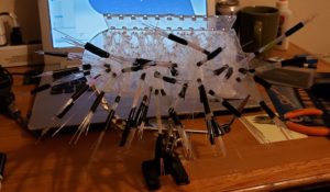
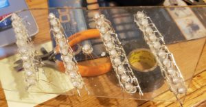
With the hole pattern cut, I then began the tedious task of wiring the fiber optics into each hole then bundling them by number. This was extremely tedious and by far was the longest process in the build. I first had to cut bout 560 6in cables from the 100m cable of fiber optic I bought off amazon. I then wired the cable and began bundling them. The cables were bundled together using a piece of shrink tube and electrical tape on the ends. I continually had to reference the CAD model to ensure I was bundling the correct cables together and additionally had to ensure the cables did not interfere with the other bundles. In the end, it was impossible to avoid tangling due to the large number of cables involved. I initially wanted to have each digit of the clock have their bundles in the same order (i.e. 0 at the bottom and 9 at the top) but due to tangling this was impossible so I needed to identify bundles through testing. An image of the bundled wires can be seen below.
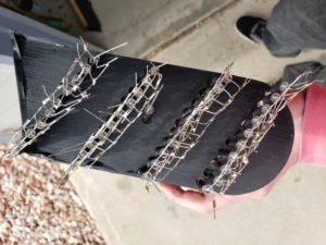
With the bundling done I then poured the epoxy over the front face of the clock and let it dry. The next step was to attach the cable to LEDs. Initially, I thought it would be easier to have the LEDs held in place by a laser cut piece of acrylic. I created the piece with the LEDs oriented diagonally the hot glued the LEDs in place and soldered the leads together. I also created a scaled-down version of the acrylic piece by hand using some scrap plastic and oversizing the holes for the LEDs. The ends of the bundles were then pushed into the oversized holes in an attempt to guide the bundles to the LEDs. I quickly realized this design did not account for the odd directions the ends of the fiber optic bundles were oriented in due to the forces from the tangle of LED bundles. To fix this I took the LEDs out of the laser cut pieces of acrylic and bent the electrical leads in an attempt to match the angle of the LED bundles. The LEDs were then attached to the fiber optics using shrink tube. For the most part, this worked, but it is evident some fiber optic cables don’t make good contact with the LEDs as they are dimmer when lit. Images of the epoxy coated the front plate, initial LED guide and the LEDs attached to the bundles can be seen below.

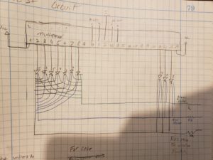
The next phase of the production and design was the electronics. A lot of the coding and electrical design of this project was out of my wheelhouse, so I was prototyping the electrical system in tandem with the production of the clock face. Initially while researching the electronics components I played with the idea of using neo-pixels rather than LEDs. This approach would have made the electronics design and coding much simpler, but ultimately I decided against this since I could not find a good way to attach the fiber optic cables to the neo-pixels. Since I was using LEDs this required I use multiplexers to control what led is lit since an Arduino does not have enough I/O pins to directly control all 41 LEDs. Since I have never used a multiplexer before this was the first prototype I made. In this prototype, I cycled through ten LEDs using serial commands to a single multiplexer. A multiplexer acts a multipath switch where the path is selected using serial commands. So for this circuit, the input signal to the multiplexer was 5v and each output Chanel was connected to the common anode of one of the LEDs. A very rough circuit diagram I used for this prototype is included below.
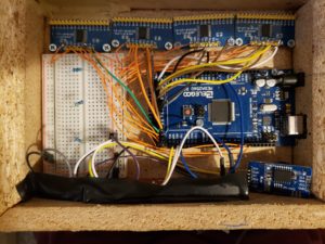
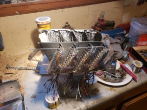
With this working, I repeated the code and wiring 4 times and added in code to create the clock. For this, I used a real-time-clock (RTC) IC and a library I downloaded of line. The code first reads the time from the RTC then depending on what number is in each digit of the time lights up the respective LED on the clock. I also added a slide potentiometer that controls the color of the LEDs. The completed wiring can be seen below.
The last phase of the production process was to create the exterior of the clock. Initially, my design for this was rather large and grandiose. The design involved the electronics housing to be slanted on three faces and to converge to a point in the back of the clock. Eventually, I realized this design would be extremely hard to manufacture and only add time to an already timely production process. This lead me to redesign the electronics housing to something that still captured the desired aesthetic but was much easier to manufacture. Both designs are included below.
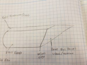
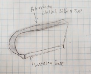
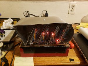
The one common aspect of these design was the metal cladding on the outside of the clock. I felt this was pivotal to the aesthetic due to Italian futurist’s fascination with industrial material. To create this feature I first used screws in the back plate and epoxy o the front place to attach the clock to the top of a simple wooden box I built. The next step was to solder wire to the leads of each LED then wiring them through holes in the top of the box. Then using epoxy I attached the old LED guide plate to the top of the box as well. The intent of this was to act as a guide for the metal sheet and additionally add infrastructure for a top support for the metal. I then bent the metal to the correct shape and attached it to the clock using three sheet metal screws, one on each side and one on top. Pictures of this process can be seen below.

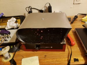
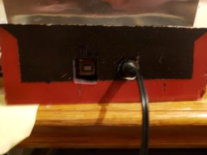
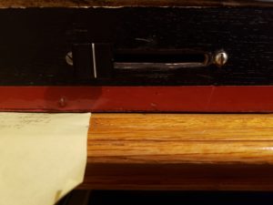
The rest of the electronics housing was relatively simple to produce. I first cut holes for the ports to the Arduino, then cut a slot for the slide potentiometer. Lastly, I painted on a design that I felt fit the aesthetic of Italian Futurism. Images of these are included below.
In terms of budget, I am under budget. I never created a detailed budget for this project but set the goal of not going over $100. Currently, I am at about $60 spent on the project. I was able to cut costs by using material I already had in my possession and using an Arduino cone that works just as well but was about half the price. An image of the final project is included below along with a video of my final presentation.
13 Comments. Leave new
what an incredible looking project. i can definitely see the coding obstacles you faced. I am not a big fan of circuits and electronics, but good job it really looks good.
This project looks like it was quite a handful. I can really see the significant amount of effort you put into the idea stage, design, and most of all, manufacturing. Why exactly did you decide to use fiber optics. If you had 41 LEDs already being used, would they not have sufficed in creating the numbers themselves? I do think that the clock looks really cool with the fiber optics though. SO perhaps it was worth the headache! As for your aesthetic, I like that you chose a very unique, less explored aesthetic. I appreciate the fact that given all the difficulties in manufacturing, you kept the aesthetic and made it a priority for your project. To be completely honest, this clock kind of went over my head. It seems to have a very complicated design and I am assuming the code for it was made by you. That must have also been fairly challenging. One thing you are not lacking in is definitely patience! The overall product looks great and seems to function as you intended, so congratulations! It was a very challenging project you decided to take on, but you executed it very well and put in both the time and the effort to get it done. Really well done!
WOW. Incredible! I really like how you chose to make each number laid out in constellations. How did you come upon that?
I really like this concept and final project! I think you could probably simplify your circuitry by just using neopixels (WSJ2812 LEDs) that way you can just use a string of them and not have to deal with multiplexers, and you could easily control different colors. This turned out really cool though, congrats!
This project went way over my head and was super creative. I think your execution went well and you nailed the aesthetic you were going for. It’s unfortunate that the lights didn’t 100% light up in certain areas but I’m sure if you were to mess with it a bit more then you could get it to work properly.
Very cool project, clocks are a big part of our society and we use them everywhere. I like how you were able to merge what you learned from coding and the art world together. Probably the most complex project in this entire class, great job.
This is awesome! There are so many parts that I don’t understand in this because it is so complex electrically with all the wiring and the fibre optic cables and the LEDs. It is really telling how much work you put in and I can’t wait to see it at expo.
Really cool final product, the circuitry is very impressive. Did you consider any other ways of securing the sheet metal to the base to avoid using screws, or are the screws important to the aesthetic?
Seems like there is some heavy arduino coding here. Way past anything I would ever want to do. Great job on the project and I think you tackled a real doosy here. Great Job!
Wow, this is complex, well done. I wonder if the LED strands can be wound in a way that makes the display brighter, other than that, I am impressed because I wouldn’t have even known where to begin.
You took on a very difficult project and did a great job. It is such a unique idea, I am amazed at the amount of detail. How many hours did it take?
I think the idea of having a clock as your project is really cool. Your presentation had a lot of images that helped us understand your aesthetic and process better. Do you think if you did this again, you’d eliminate some of the aspects?
I was previous unfamiliar with the Italian Futurism aesthetic, but it looks like you captured it well. It looks nice and like you put alot of work into it. I wonder if you would be able to make it brighter and easier to see during the day.