

Three-Position Ice Tools
 My final project for this course was to design and manufacture a pair of ice tools for use in both competitive and natural settings. Over the past couple of months, I have gone from vague goals to ideation, design, and manufacturing to make a pair of ice tools that are optimized for the technical movement and intense strain of competitions, have three positions for optimal efficiency and reach, and yet can still be swung into ice.
Inspiration
I knew immediately that I was going to be designing ice tools. In fact, the resources and opportunity to use a machine shop to do it were why I signed up for the class in the first place.
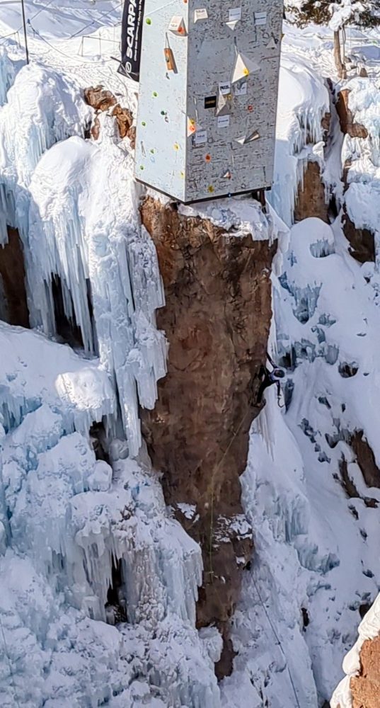
I’m an amateur ice climber just getting into my first few competitions, but competition-worthy tools are expensive, and the best ones are extremely so. My partner is a world cup ice climber (pictured right) so I was able to borrow their tools for a while, but talking to them and the other members of the US and Canadian national teams, they all modify their tools in some way. They take a premanufactured tool and remove and reconfigure the handle and pick layout to make it more aggressive and technical. From this, sometime last year, Elvin C. and I had the idea:
Just how much better could you make an ice tool if it wasn’t a question of modification… what if we designed them ground up and made them from scratch?
Ideation
 The downside of building the ice picks as part of this class was that they would have to be distinct, no group projects allowed, so Elvin and I set about each designing our own tools and we would see at the end of the semester which ones worked better. All that follows are my designs and my process, I highly recommend taking a look at Elvin’s posts to compare and contrast what he did.
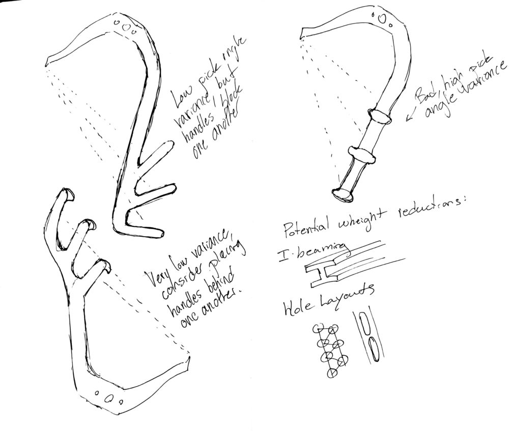
I started by sketching some ideas, I knew I wanted to create something new, a pick layout that you couldn’t buy from anywhere, and that solved some of the issues that the US team folks had communicated to me about preexisting tools.
I decided what I wanted to achieve was a tool that could be used both on ice and in competitions with three positions, all useable in both disciplines.
3D Modeling
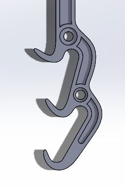 Once I had a general idea of what I was going to try to accomplish I started working on a 3D model of the tools in SolidWorks. I hadn’t done a whole lot in SolidWorks, the vast majority of my CAD experience was in Inventor so it took a little bit of getting used to and I was slow at first, but eventually I was able to gain some proficiency in it. I started by mapping out the pick-angle layouts for various high-end ice tools to get an idea of what would be required, then set to work trying to make a compelling shape to house them.
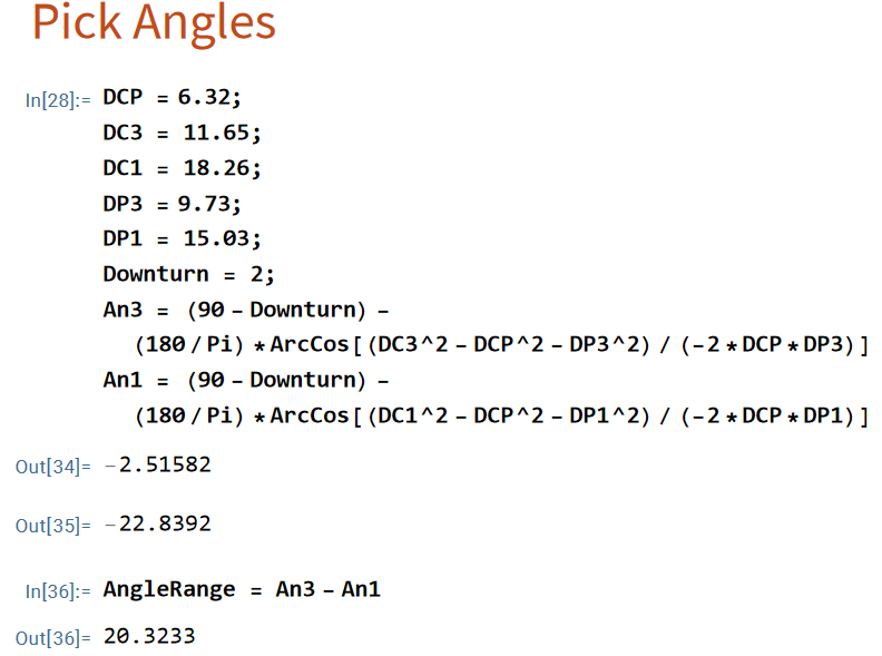
3D Printing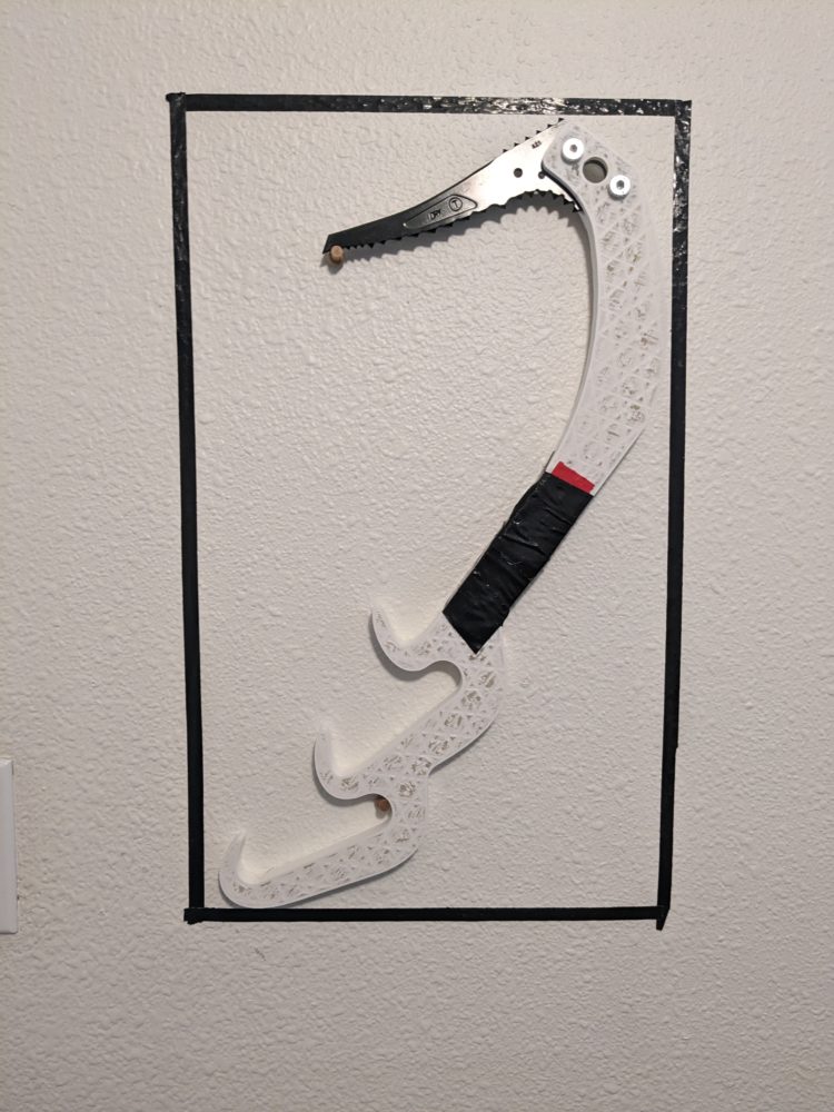
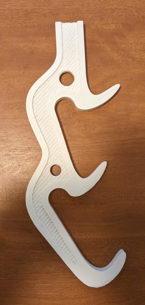
Once I had the shape I wanted and my best guess at the ideal parameters for width, angle, handle spacing, I-beaming, weight reduction, and baffling, I 3D printed the design. I ended up making two 3D prints, one of just the handle layout to test hand-swapping logistics and a few weeks later the entire tool to dial in and compare the various pick angles.
The first print helped clarify the sizing of the hand positions and the pommels and generally confirmed to me that the idea could work.
The second print made it obvious that in my initial design, the pick angle compression had worked but that all positions were too steep and needed adjustment. Also got proof that it would meet the size requirements (hence the black box).
Machining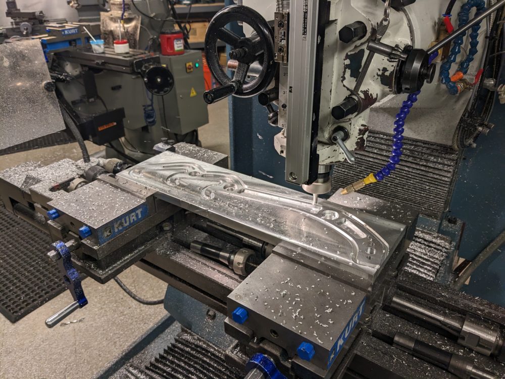
I am studying physics, so when it came time to actually manufacture the tools I was out of my depth. I’ve done a fair bit of designing, and I know the general factors that make a part easier to machine and did my best to implement them, but that was as much as I knew. Fortunately, I had help. We found a large piece of three-quarter thick stock 6160 aluminum in the ITLL large enough to comfortably fit four tools, all in one piece. First, was cutting down the stock into the appropriate sizes, then faced the pieces to obtain blanks for each tool.
From these blanks the tools emerged, each taking about 5 to 7 hours of pure run time on the CNC, taking them all the way from blank to outline to contour to a rough cut of the final form.
Finishing
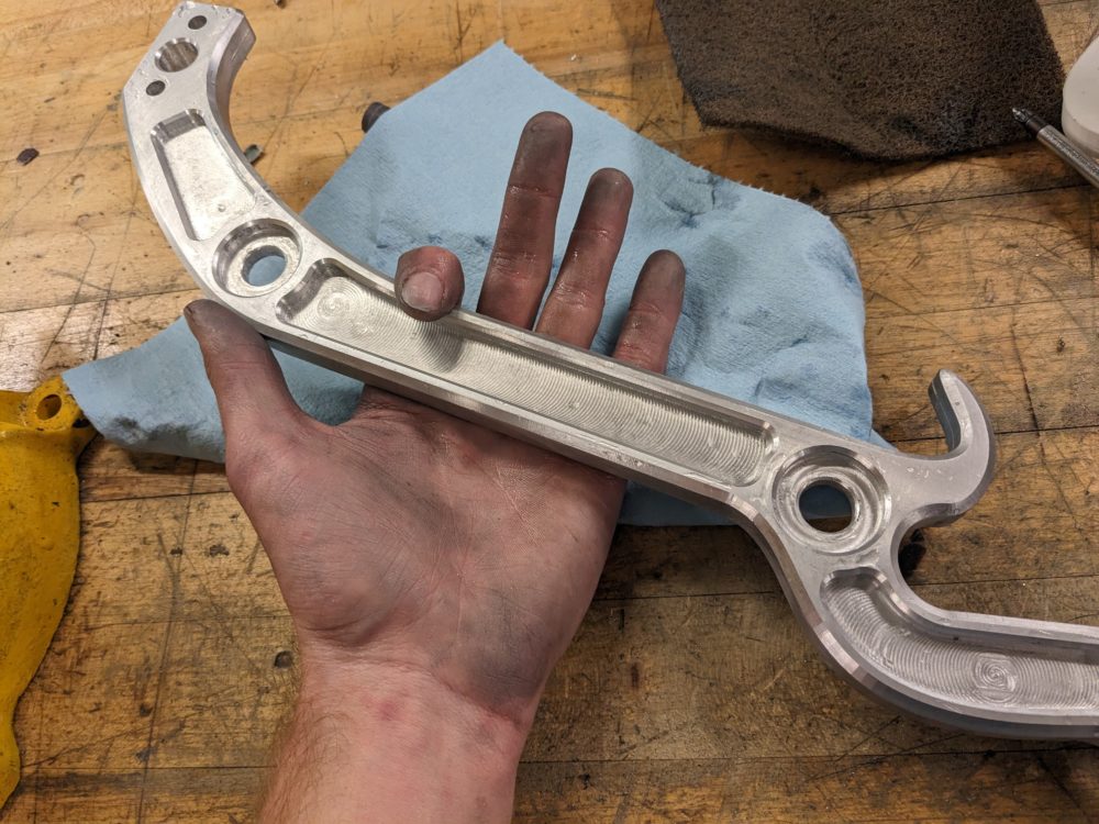 Once the rough-cut tools came out of the CNC they were 98 percent done but there was some finishing work to be done. Firstly they had to be cut out of the blanks and the supports that kept them attached. Next, I had to grind down the thin seem that separated the two halves of the CNC’s tool path. The two paths had a slight offset so I was never able to fully make it disappear but I ground it down, filed it, sanded it, and buffed it until it was smooth enough to drag your hand across without discomfort. I did the same for all the sharp edges on the tool. Lastly, I used a saw and file to deepen the slot at the head to accommodate the picks.
To test them I also wrapped them in bike tube and tennis tape so that they can be bitten comfortably in order to switch tool positions. Eventually, I would like to clean this up and fill the I-beaming with something other than bike tube but I’ve run out of time so that will be a post-class modification.
2 Comments. Leave new
This ended up really cool. I really like the finish of the end product
I really love the sketches, it really portrays your thought process. Great prototypes too!