
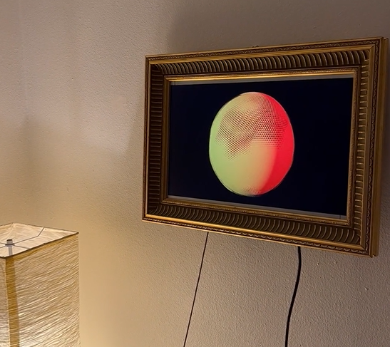
I have finished constructing the physical device of the digital picture frame. I used duct tape to hold the monitor in place and screwed in three wooden struts to hold the monitor in place. I then used picture mounting d rings and copper wire that were from the original painting. I am very excited about how the physical device has turned out as the aesthetic is even better than I had envisioned.
I then brought the digital frame home so I could hook it up to my laptop and display youtube videos.
The Next step of this project was to use blender to create infinitely looping renders. I was inspired to do this because it reminded me of concert visuals and live art. I have never used blender before so I decided to follow tutorials on youtube. The first render I made was for my senior design project of our device in an ocean. I then had to figure out what I wanted to make for the picture frame. I really like the idea of unexpected motion or ripples, this was the inspiration behind the first render. I decided to have the texture be 4D so it moves in and out of the sphere, during the animation I set keyframes at the start and finish. In these keyframes I changed the motion value so that it starts and stops at the same position, this is what allows the render to be infinitely looping. In this example below the animation is 5 seconds and runs 3 times to the same render time. I rendered the images on a black background and used two spot lights at different intensities. I chose Red and Yellow for colors and set them at different angles. What I really like about this light setting is that the material is gray which allows for shadows to be formed underneath the texture. However this animation took a long time to render because of how many detailed shadows are in each frame.
In the next render I followed a couple different tutorials and combined them for my own spin on the animation. This animation was much more complex for me as I used the material shaders.
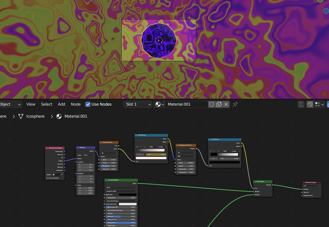
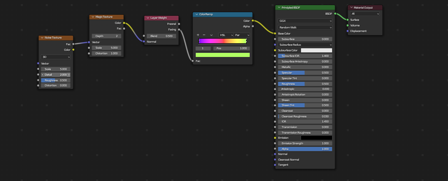
These are the nodes that create the material for the isosphere shape that the camera is rotating around. Basically whats going on here is that the material has a musgrove texture that overlays the surface. The musgrove texture is a blotchy black and white texture that will show/ cover the material based on the white/ black color ramp sliders. The fractal/psychedelic pattern is created by editing the scale of the musgrove pattern, noise, and the colormap. There are many many patterns you can create with a material shader package like this. For the background I created a cylinder that was larger than the radius the camera was swinging around, this way the background is 360 degrees. I then added a color ramp to select a spectrum of colors that I liked, and used a magic texture to change the color of the cylinder based on perspective. The pattern size was controlled with the layer weight node. I did my color ramp differently this time by using HSL colors and selecting a range from the spectrum.
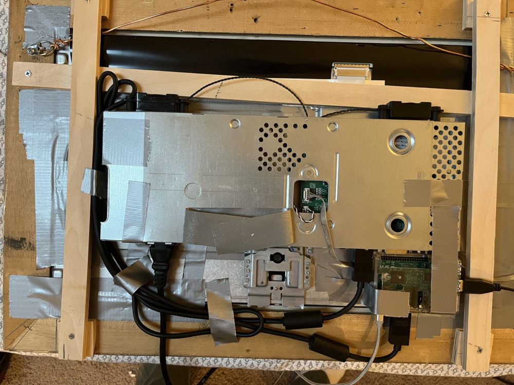
The next step of this project was to set up the Raspberry Pi. This was a big challenge for me as I have never used a raspberry Pi before and do not feel comfortable with electronics. I started by going to the Raspberry Pi website and installing the image reader. The next step was to install the Raspberry Pi OS on the micro SD card and then plug it into the device. I then brought the Pi home to set it up for looping videos. This was not as simple as I thought it would be, as the model I had did not have a wifi card. So what I had to do was bring my entire computer set up to the corner of my living room where my router was as I needed a direct ethernet connection. I then booted up the Pi and installed all of my images and videos.
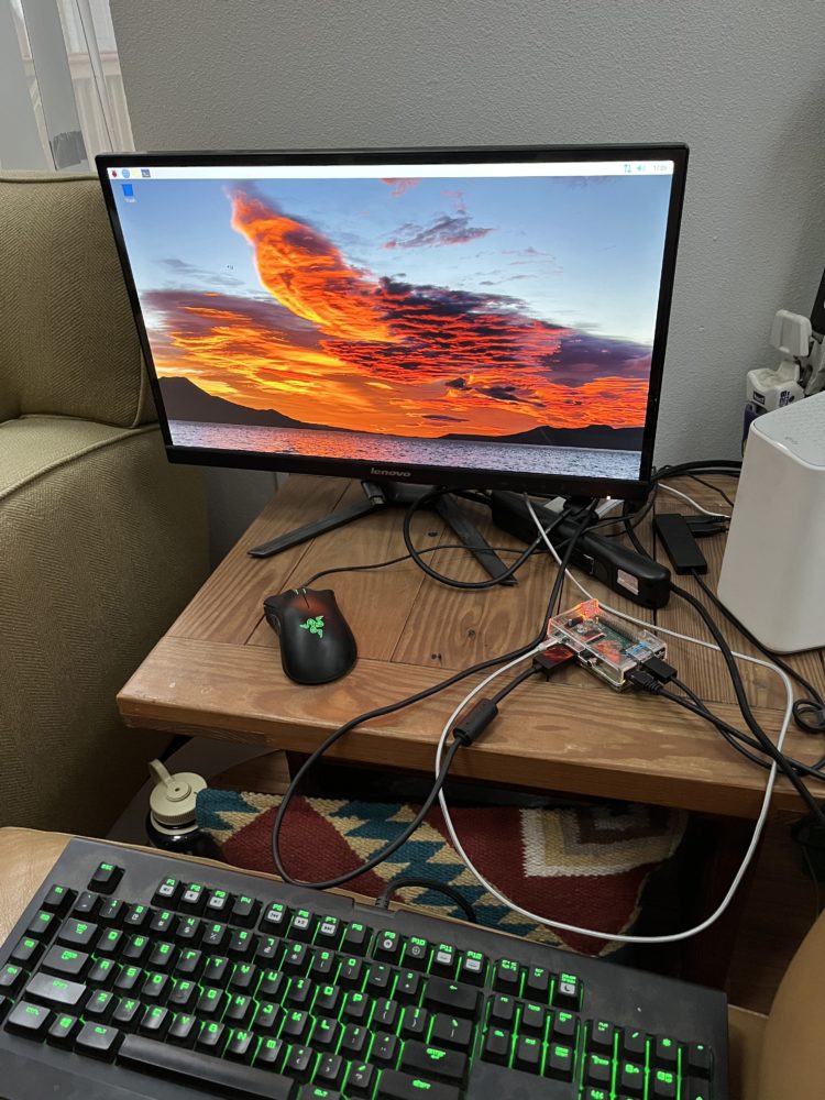 This is what setting up the Pi looked like. The last step was to install the Pi and various coords onto the back of the picture frame resulting in this image.
Lastly after putting everything together I ended up with this video. I am very happy with my final product and proud that I was able to complete this project. If I was to do it again I think I would use a laptop screen and buy a board off of ebay as this project is rather clunky and heavy. I also would opt for the device to be battery powered as I do not like the look of the coords.
Video Recording of my Final Presentation.
4 Comments. Leave new
Hey Luke! This is super cool. What was your initial inspiration for this device? Reminds me of Samsung’s TV that is meant to look like a painting.
Hi Hunter, this is exactly what one of my inspirations was. I wanted to that that idea and do it in my own style.
Hi Luke, this is a very impressive project. I admire your dedication to learning and using electronics that you were completely new to. It looks like there are couple strips on the top and bottom of the frame where the monitor is still visible, are you planning on modifying the frame at all to hide those?
Hi Alex, I was planning on using a mat board to frame the screen in a white paper. However, after the project is completed I enjoy the look of the metal frame. I do not think I am going to change anything from here on.