
One of my friends was a great inspiration for this project. While talking about personal projects and watches, he mentioned that he had 3D printed the case and made a watch winder for himself. We got into the specifications, and he explained that he used a stepper motor and an Arduino to make the watch winder quickly. He uses it frequently, and it helps keep his automatic watch running smoothly.
I recently got an automatic watch from my girlfriend for my birthday. So, when we were discussing the watch winder, I realized that this would be an excellent personal project for me to undertake. This occurred at the beginning of the semester. I didn’t have the motivation to make it, but when aesthetics and design took off, and I was brainstorming ideas for my second project, I realized that this would be a great fit.
After conducting extensive online research, I found several guides on how to make a watch winder at home. I realized that most of the designs were not very exciting, so I began to think about what else I could do. That is when I came across the practical engineer’s design for a gyroscopic watch winder. This inspired me, and I immediately began investigating ways to create a watch winder that operates in a gyroscopic motion.
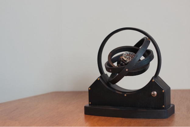
Figure 1: Inspiration made by Practical Engineer
The practical engineer’s design is fantastic, but it is also very complex to make. The design requires numerous woodworking skills and appears to be a long-term project, which is slightly out of scope for this class. Additionally, as senior design ramped up, I realized I could not spend that much time making a fully wooden watch winder. These realizations led me to search for alternative designs and eventually to Fugatech 3D Printing’s YouTube channel.
The watch that I found on the channel is what I was looking for. It was a gyroscopic design that was much more appealing than the traditional 3D-printed winders, but it was also much simpler to manufacture than the completely wooden one. Fugatech’s YouTube channel showcased a complete assembly, linking many components. The CAD files cost only about $2.89, and they were the main inspiration for my design. TI used all of their files and made some slight changes, such as adding fillets around the design, to make the lines a little softer and more in line with my aesthetic, which is mid-century modern.
My vision for the project is both functional and aesthetically pleasing. While considering the aesthetic, I landed on mid-century modern. The reason for this is that I have been getting a lot of mid-century modern TikTok videos about furniture recently. I don’t know what prompted the videos to appear on my feed, but they led me to the aesthetic that I pursued. The function is that I can push a button, and the watch winder will spin. Ideally, this will help replenish the reserve power in my automatic watch and keep it ready to use whenever I wear it. I have yet to test the project’s function, but I hope that keeping an eye on it for 30 minutes before I go out will be sufficient.
The form for the project is mainly based on the round geometries of a gyroscope. This reflects the complex geometries of mid-century modern design to me. I also wanted something that would look impressive when displayed in my room. Because of this, the gyroscopic watch winder was an easy choice.
Overall, I am looking for an impressive and functional piece of furniture that I can use for years to come. Additionally, if it goes well, I will likely make some for my family and give them as gifts, since they are also avid watch fans. I also hope to enhance my skills in electronics through this project. Honestly, the manufacturing is complete, but I am still working on the electronics, so I hope to finalize that soon and be able to showcase it at the expo.
Below is the initial sketch that I drew regarding this project. I was thinking about completely modelling and fabricating the project without anyone’s help, but I quickly realized that I do not have the time to do it because I am taking 18 credits I have had to balance my time very carefully to ensure that all of the classes I am doing can get quality work out of me.
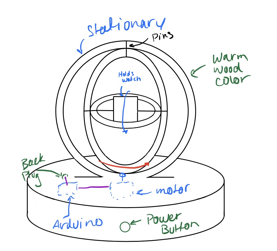
Figure 2: Initial Sketch
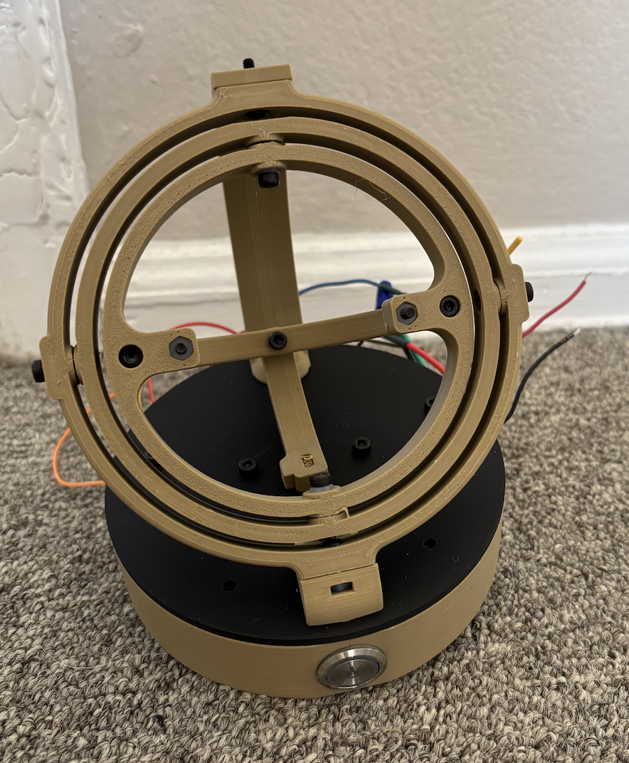
The project ultimately turned out to be quite similar to the initial sketch. There are some differences based on the fact that the actual circles will be rotating in different ways, and the gyroscopic features will be set at an angle. Additionally, some extra supports were not depicted here. The warm wood color is something I attempted to achieve by using “wood” colored 3-D printing filament; however, in all honesty, it is more of a tan color.
Mid-century modern is a terrific aesthetic that brings warmth and organic design into different spaces. The primary setting for mid-century modern design is furniture. You will commonly see chairs and other pieces of furniture labeled as mid-century modern, but I am trying to emulate this aesthetic in a much smaller package. To achieve this, I am trying to incorporate warm colors. As mentioned before, I also use complex shapes.
Mid-century modern often employs organic shapes, so I am attempting to incorporate this style with the circular elements used throughout the design. There are numerous circles in nature, and life itself can be viewed as circular. The most significant contribution to the mid-century modern style comes from the geometries and colors I use.
For the CAD files, I was unable to create an assembly using the files provided by the Cults3D website. All of the files were provided in an STL file format. The STL file format takes the part and converts it into a mesh figure. This makes it challenging to work with. I could create solid bodies from the parts when importing into SolidWorks. However, they still lacked many functionalities as parts were created entirely in SolidWorks. The primary issue lies in the assembly area.
While trying to make the assemblies, many of the faces could not be selected. Edges and holes also could not be chosen. As you can imagine, he designed a gyroscopic watch winder primarily consisting of circles, making it challenging to assemble in SolidWorks. For this reason, I will attach all the different pieces and describe each. I will also include a picture of what the final product should look like.
This is what the watch is intended to look like, as created by the person who designed all the CAD files. They are using a different color palette than I am, but overall, they share a similar vibe to my work.
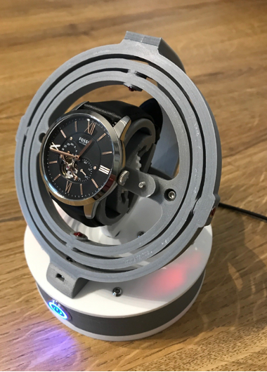 Figure 3: Design as shown on Cults3d website
The design shown above is very similar to how my final design will look, but I have filleted all the edges possible to give it a smoother overall appearance. The softer, filleted edges hopefully contribute to my mid-century modern aesthetic. I will now start by showing figures of the CAD models of all the actual rings that you can see in the picture.
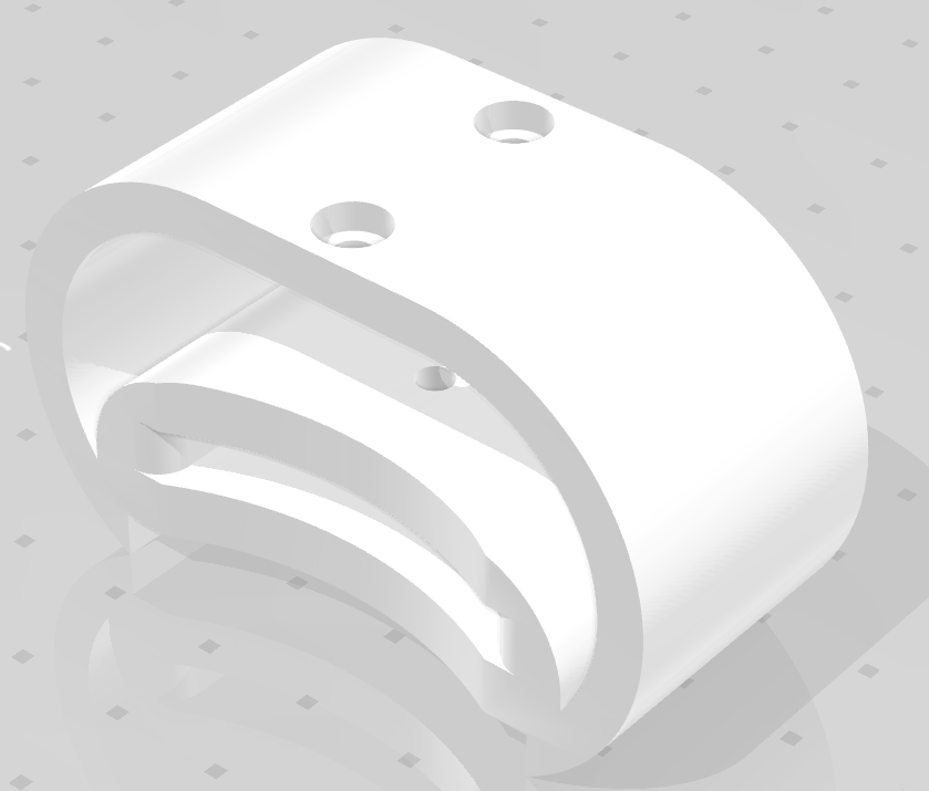
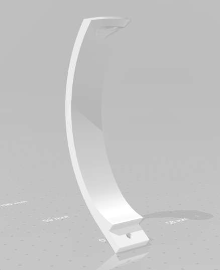
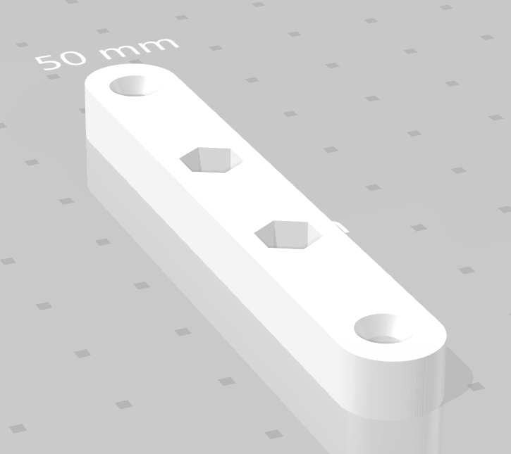
Figure 3: Watch support, ring support, and extra support
The three pictures shown above are all crucial components of the assembly. The piece to the left is what the watch is fastened around during the actual operation of the winder. In the middle is a support that attaches the ring to the exact base of the assembly. Then, to the right is a piece that is secured to the watch support and connects the support to the rest of the winder.
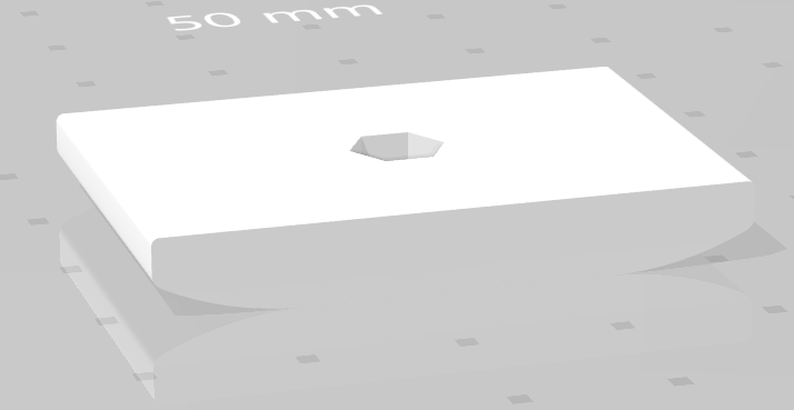
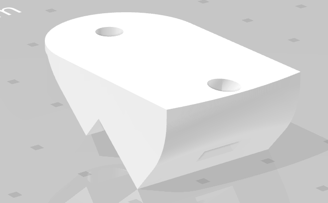
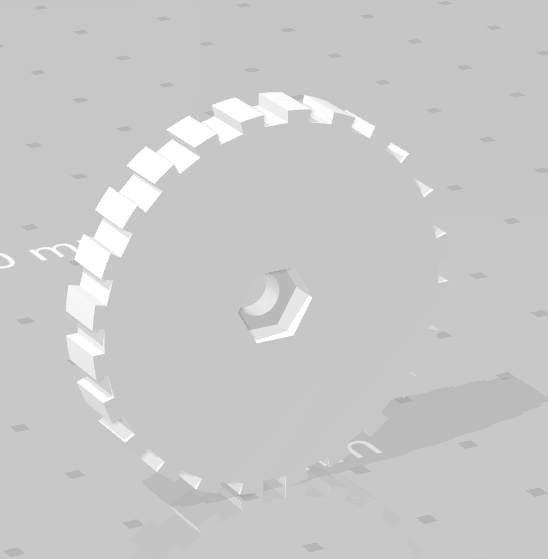
Figure 4: Bottom of watch support, extra support, and gear
The pictures shown above are smaller parts of the window. On the left is a piece that is used in conjunction with the watch support. It sits at the bottom of the support and extends outward to increase the size of the watch support, allowing it to hold watches more securely. In the middle, there is a support for the large ring that gets fastened in the front of the base. Then, on the right, is a gear that is used in conjunction with the bottom of the watch support on the left to create the adjustability of the watch support.
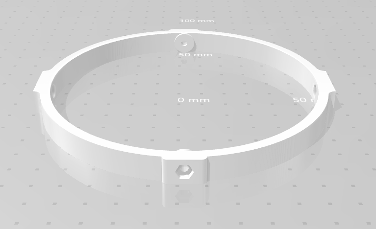
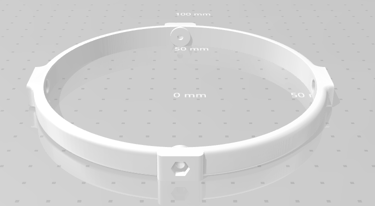
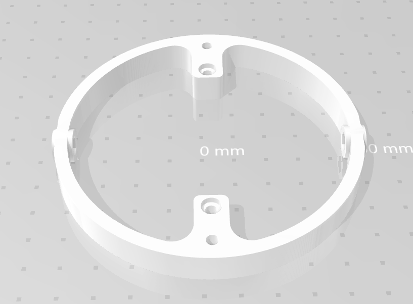
Figure 5: The rings for the gyroscope
All of these models are parts for the gyroscope. The one on the left is the largest ring, which will be on the outside. The one in the middle is the middle ring, and the one on the right is the smallest ring, which will be the innermost. The middle ring and the smallest rings rotate while the inner ring on the outside remains stationary.
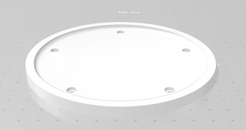
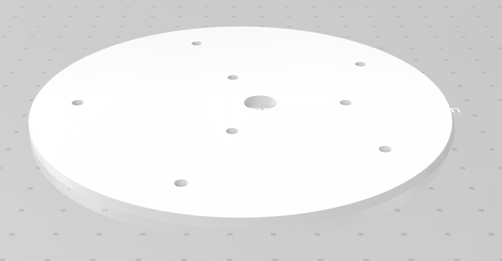
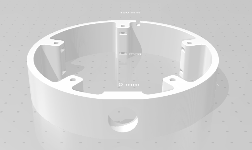
Figure 6: The assembly for the base
These three pictures are all the parts that make up the base of the watch winder. The one on the left sits on the bottom of the base. As you can see there is an outcropping to hide the screws and give it a stand like appearance. The picture in the middle shows the top of the base, this can be seen by the additional mounting holes that allow you to mount the top components to the base. Then on the right is the middle of the base, you can see all of the columns which are used to screw in the top and the bottom and thee hole for the power button.
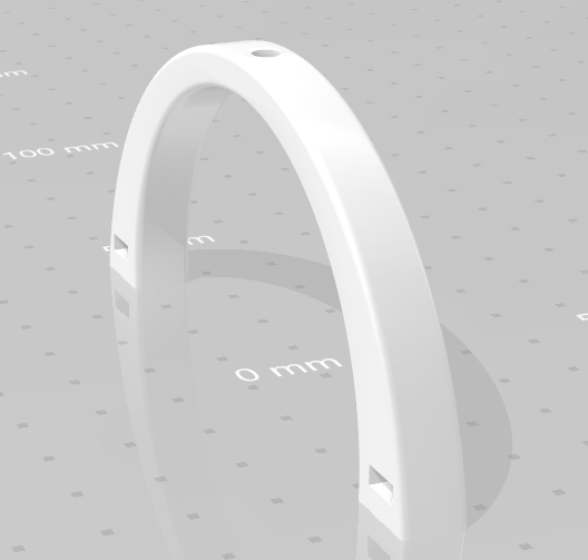
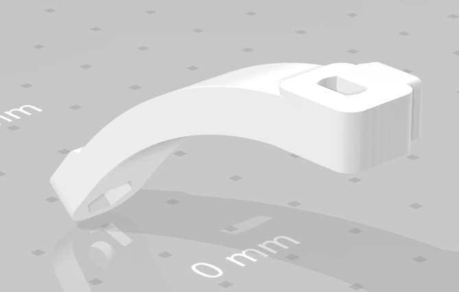
Figure 7: A support and the movement arm
These are the final pieces, and make the actual movement of the device. The picture on the left shows a support that is fastened to the innermost ring and is used to move the gyroscope. The hole on the top is attached to the piece shown in the picture on the right, which is then attached to the stepper motor to move the watch winder.
These are all of the components that make up the assembly, I give full credit to Cults3d and the publisher of the files for creating them, all I did was modify them to suit my needs better.
Credits:
Inspiration: https://www.youtube.com/watch?v=9xmiwsT9VRI
Feature Picture: Myself
Figure 1: https://practical.engineering/
Figure 2: Myself
Figure 3-7: https://cults3d.com/en/3d-model/fashion/gyro-winder-watch-winder-remontoir-montre?srsltid=AfmBOorMWaezYh3AMaR7ixzpe82b-rDkKLTsjXLt6l3GPKj4u9BSh_dh
2 Comments. Leave new
This is a very unique and technical project. Your execution was awesome I love the way it looks. If had to change one thing about it, what would you change?
This is such a cool project, your attention to both function and mid-century modern form really stands out. I’m curious: how did you decide on using a gyroscopic design specifically, rather than a simpler rotation mechanism, especially knowing you’d be balancing a heavy course load at the same time?