
Description
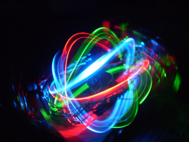
The LED Orb is a device that spins three LED’s (one red, one green, one blue) at very high speeds in three different axis with varying flash rates to create a cool light effect. I was inspired to make this after I saw a video (linked in the references below) of the first LED orb. It was ‘garage engineered’ with remnant materials and recycled electronics but the final product worked really well. I thought that if I ever made my own LED orb that it would be properly made and I got the opportunity to finally work on this project through this class. I chose this project because I have always wanted to make one and I wanted to learn more about electronics, circuits, and how to use the 3D printer and laser cutter, all tools and skills that I have not used in my undergrad career. Along with using the 3D printer I had to also learn how to model something on SolidWorks to be 3D printed which is a challenge in itself.
Design
My overall goal for the design of the frame and the circuitry was for it to be simple, easy to assemble and disassemble (for repairs), not take away from the light show, and the frame was to be 3D printed. After talking to Pat in the Idea Forge and Dan in the ITLL I found out the circuitry for this project was simple, which was a huge relief considering I have very limited circuit knowledge. Next was CADing everything in SolidWorks which became the biggest challenge of the project. Not only was every part small (to house the electronics and to decrease the weight), it had to be printable. I have plenty of experience using SolidWorks but no experience designing for 3D printing. I spent a lot of time modofying and interating on all models to account for all the factors that went into the frame design.
I broke up the entire assembly into a few sub-assemblies: disc, truss frame, and U frame.
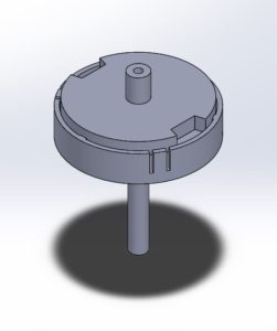
The disc houses the LED’s, is attached to a motor on one side and a bearing on the other. It consists of two pieces as shown below. The top press fits into a motor and press fits to the other half of the assembly. The two large cuts through the top are so the disc can be disassembled. The bottom half has slits where the LED’s will protrude and the bottom shaft connects to the bearing in the truss frame. It is also hollow and houses the wires that connect to the LED’s in the disc and to a slip ring in the truss.
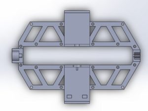
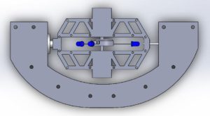
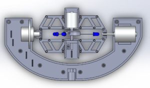
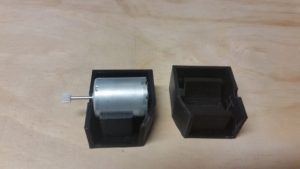
The frame assembly houses the small motor and slip ring that connects to the disc assembly, and connects to the U frame assembly with a larger motor on one side and a slip ring on the other. The holes throughout the truss are for fasteners to hold the assembly together. I went with a truss design because it would be stable and have a low profile, so it would not take away from the light show. The motor and slip ring housing I designed to be hidden from view so that it would not distract the viewers. This was also designed in 2 parts for ease of 3D printing and assembly.
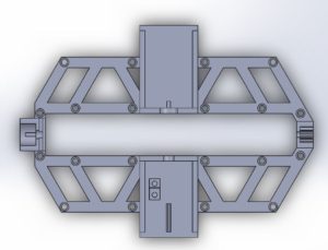
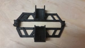
This is the bottom half of the truss. In this orientation the motor housing is in the top middle, slip ring and counterweight in the bottom middle, it attaches to the U frame slip ring on the left side and the motor on the right.
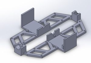
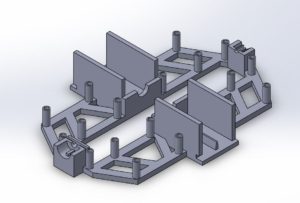
The top half of the truss is mainly used to hide all the components from view and secure the motor in place.
Lastly is the U frame which houses the slip ring and larger motor that spins the truss frame. It will also connect to the stand which houses a small circuit board and the large motor that spins the U frame.
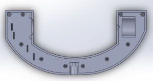
The bottom half of the U frame shown below also houses a few counterweights to balance out the weight of the motor. The slip ring is held in place on the left side and the motor on the right. The small holes throughout are for the fasteners to hold the assembly together. The small features are used to prevent the slip ring and motor from rotating in place.
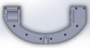
This is the top half of the U frame. The features on this part are used to hold the motor and slip ring from moving laterally. The circular feature in the middle bottom of both parts will connect to a hollow shaft that the largest motor will spin. The shaft will carry the wires down to the circuit board and act as a slip ring.
Here is the top level assembly that shows how everything fits together.
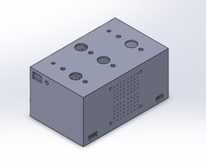
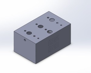
Here is the control panel that will have switches to turn the motors on and off individually, two potentiometers to control the flash rates and brightness of the LED’s, and a switch to turn the sound detector on and off. This will also house the Arduino and since it might heat up in the box I added holes to secure a PC fan to the inside of the box to cool it. All sides and features of the box will be laser cut.
Manufacturing
This project took way longer to design and build and with senior design and other classes I only had time to 3D print a second round of prototypes of each part. The 3D printers in the ITLL were also being used around the clock so I did not have a chance to use them. Luckily 2 of my friends have their own 3D printers and let me use them.

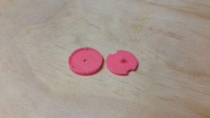
The disc printed better than expected, only a few modifications are needed.
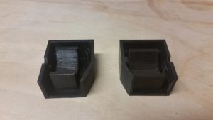
The bottom half of the truss did not print properly (the top part with the motor mount wasn’t properly heated during the printing process).

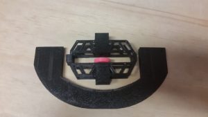
The top half printed out really well and as you can see in the next picture the two pieces fit well together.
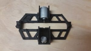
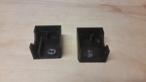
My first round of printing the U frame I only printed the motor mount (as seen above) and the slip ring mount (below).
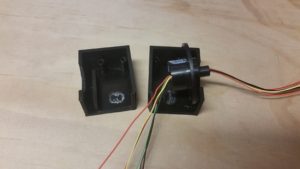
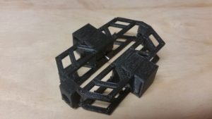
Here is everything arranged together. (The overall U frame did not print properly so we had to cancel the print part way through).
I wish I had a final product to present, but I just didn’t have the time to finish it. I feel like I am 90% done with just a few modifications to the CAD needed and after everything is printed the wiring and assembly should not take long. I will be in Boulder over the summer so I will be finishing this in May and June. Once it is finished I’ll be posting on the blog and videos to YouTube.
| Items | Cost |
|
|
|
| Arduino Inventor’s Kit: | $110 |
| LED Rocker Switches (x4): | Free |
| Rotary Potentiometer: | $0.95 |
| Black Knob: | $1.50 |
| Ribbon Cable + Pin Header: | $5 |
| Breadboard: | $5 |
| Sound Detector: | $11 |
| Slip Ring: | $15 |
| Small DC Motor: | Free |
| Larger DC Motor (x2): | $7 |
| PC Fan: | Free |
| Bearings: | Free |
| Fasteners: | $8 |
| Acrylic: | $24 |
| PLA Filament: | $25 |
| 500 mA AC Adapter: | $15 |
| Misc.: | $15 |
|
|
|
| Total | $242.50 |
| Overhead + Reusable Parts | $188.50 |
I bought all my parts at Sparkfun and McGuckin’s, and all the free items I found in the ITLL project depot.
References
- https://www.youtube.com/watch?v=sO2-tqoyGik
- http://laserpointerforums.com/f57/led-orb-2-0-a-50012.html
8 Comments. Leave new
[…] Final Report Part 1 […]
Here’s another comment for the presentation. Haha. Good work again.
Really cool project, and I understand your pain that you didn’t have time to finish. I am in the same boat, and its mostly personal pride for myself too. You definitely put a lot of effort into the 3-D printing, the COST, and CAD design for your final AOD project. Maybe we can meet over summer and work together on finishing our projects. But the time already spend working on the devices structure, electronics, and purchasing will pay off in the future! Overall awesome work.
Such a cool project idea! I hope you finish it. Do you think you could have saved time if you did not try to 3D print all the parts?
It is very cool! What are you going to with your LED orb? I like the look of you design and it can be seen that you spend quite a lot of time in manufacturing! Great job!
It is a bummer you couldn’t get it quite finished but it is looking really cool! Great design!
I know how tricky the heating can be trying to 3D print components – it looks like the most of it came out really well though! I am very impressed by your designs for the truss system, it definitely shows that you have put the work in to create sophisticated and well-structured pieces. Do you plan on prototyping the LEDs and wiring before continuing with before the CAD modifications? What future plans do you have for your LED orb? Nicely done on all the prototyping thus far, and good luck with the future final product!
Nice job on your project, even if you didn’t finish it. I can tell you obviously put a lot of time into it though from your detailed Solidworks models and solid design, just didn’t have enough time I guess. Now that you don’t have to limit your project due to time constraints, is there anything more you could add to your orb to make it even better? And what are your plans for the orb when it’s done? Use it as a house decoration?