
For my main design project, I decided to build a set of front suspension uprights for my 1965 Ford Mustang race car. In my last post, I described my design process in which I developed requirements that drove my decisions towards iterating a final design. The characteristics that defined my design include wheel hub choice, brake package, wheel size, desired kingpin inclination angle, desired caster trail values, scrub radius, and predetermined control arm geometry. I was able to then develop a SolidWorks model of the upright which satisfied my design requirements.
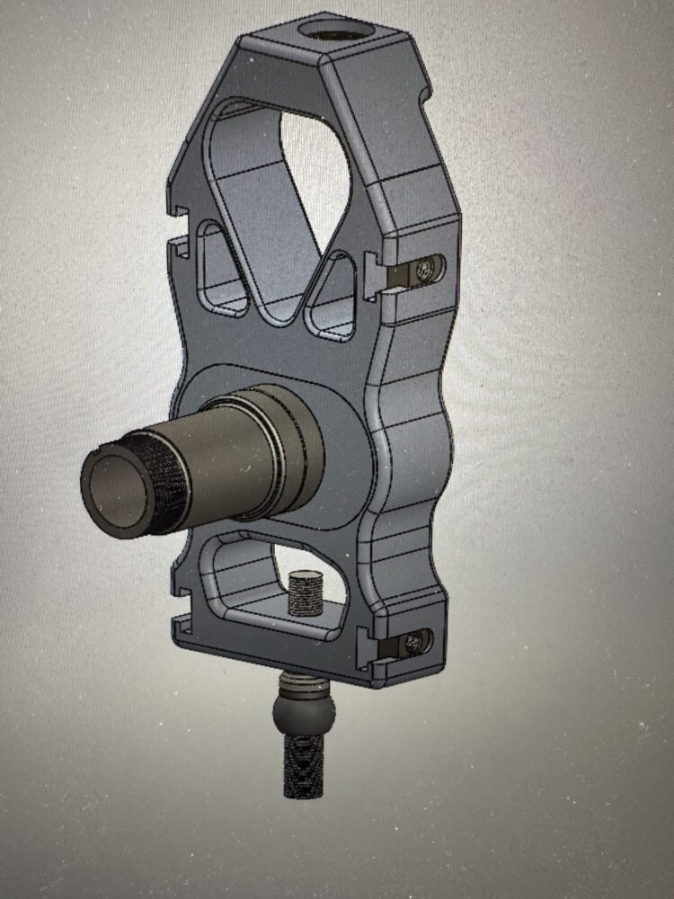
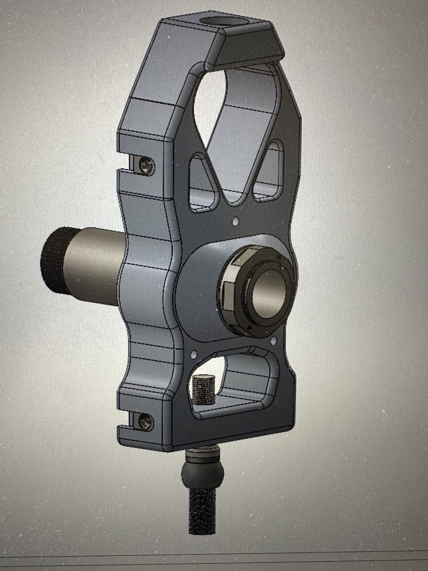
The image shown above illustrates the finalized solid model of the front uprights including the upright body, adjustable spindle keys, spindle pin, and retaining nut components. I have also chosen to produce the upright body and spindle adjustment keys from 7075-T651 aluminum bar stock due to the light weight and high strength characteristics of this material. Additionally, I have chosen to produce the spindle bearing pin and retaining nut from 4140 chromoly steel due to the high strength and wear resistance of this material. Unfortunately, I have encountered challenges sourcing the 4140 chromoly steel at a competitive price and I have struggled to find access to a CNC lathe that can easily turn the hardened steel to my desired shape. As a result, I may need to modify my manufacturing plan of this project and machine the spindle pin and retaining nut from plastic as a prototype to meet the deadline for Expo. However, I have been successful in sourcing the aluminum for the upright body and keys. Additionally, I have begun CNC machining operations of these components using a 3-axis mill owned by a friend of mine.
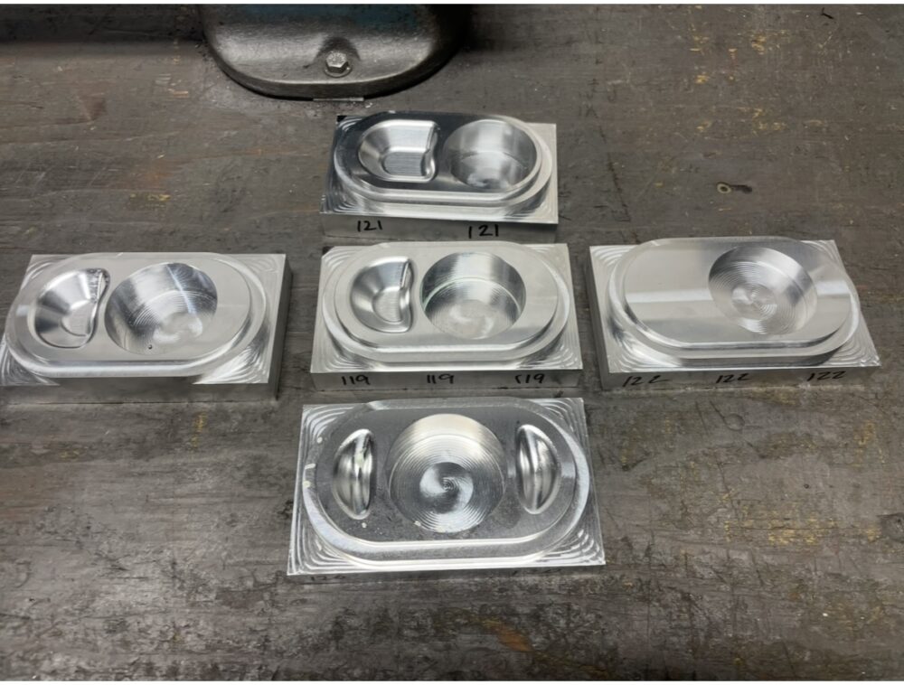
The image shown above illustrates the first operation in machining the rear spindle keys on the CNC mill. I ultimately decided to create three different spindle pin offsets including a centered key, a half inch offset key, and an inch offset key. These different offsets will allow me to test the race car at different levels of caster trail and choose a key that gives me the best steering response of the vehicle. The next steps toward manufacturing these keys include machining a set of soft jaws to mount the keys upside down in the milling vise to perform the second milling operation.
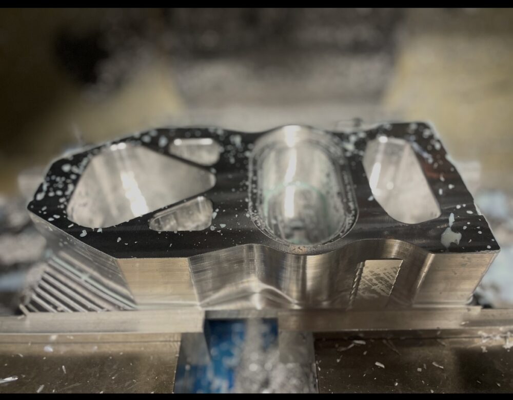
The image shown above illustrates the first CNC milling operation in the production of the aluminum upright body. These components are quite complicated and will be completed in a multiple step process with some of the features created using manual milling operations including the bore for the spherical mono-ball bearing which is located on the top of the upright body. I anticipate that the upright body will be the most time intensive component to manufacture due to the complexity of the geometry.
4 Comments. Leave new
Amazing work! looks complex and I am glad you jumped on with good progress so far. I got to see that 65 mustang in the final report.
Hello Anthony, thank you for the comments. I will make sure to add a picture of the full car in the final report!
This is such a cool project! I’m curious, are you planning on anodizing the aluminum at any point? I think it could add extra durability and a nice aesthetic finish depending on what you’re looking for.
Hello Brenton, thank you for your interest in this project. I think that anodizing the aluminum would add a nice finishing touch to the components of my assembly and extend the service life. I will consider this in the future and price out potential solutions to add anodizing.