
Over the past few weeks, I have made some progress on my low-profile microphone boom arm project, which is designed to fit within the minimalist aesthetic of my room. I have gathered the materials needed to assemble the thoracic build, specifically the hex nuts and foam, which are intended to reduce the vibrations that would normally reach the microphone unit. However, that doesn’t mean I haven’t encountered my fair share of issues and complications, some of which I was expecting and some I did not. Let me start with the model aspect of the project that I have completed.
Modeling:
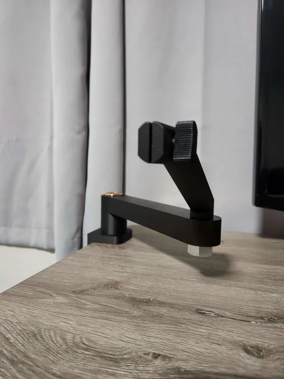
As for the design and modeling phase of the project, it went somewhat smoothly; I had previously modeled the table mount and the first arm of the assembly. An image of that is provided below for reference:

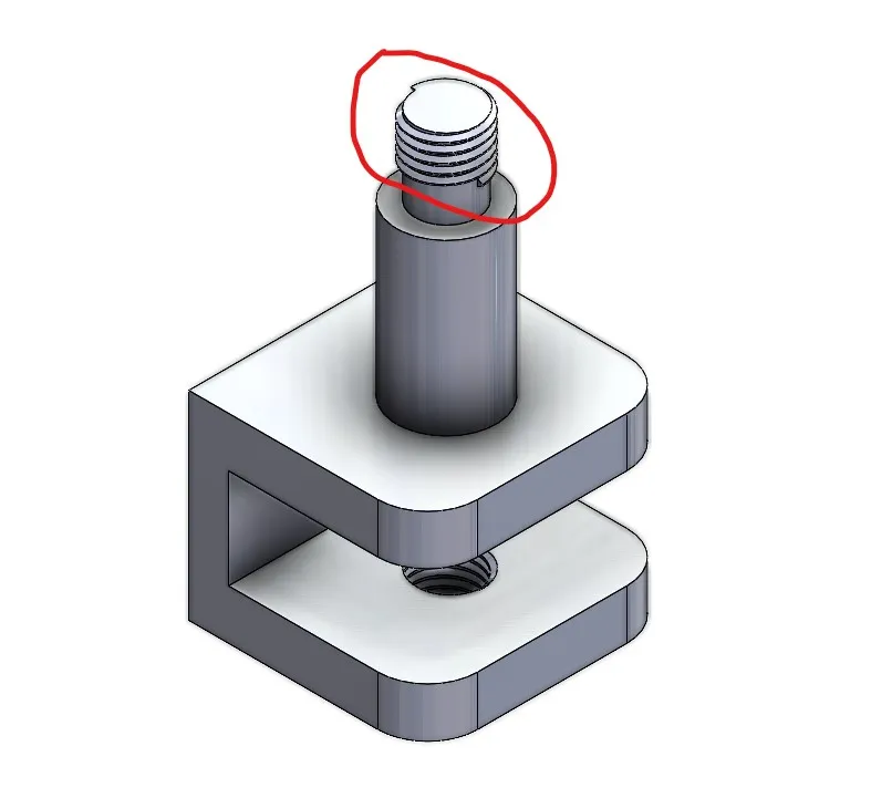
These parts were printed shortly afterward using the Markforged printer at the ITLL with Onyx material, which, to my surprise, fit together without any issues. However, when it came to inspecting the threads, that was where my problems began. In SolidWorks, I had originally selected the threads to be 0.625″-11 and had ordered a bolt that should have been compatible with that connection. However, upon receiving the actual print, I realized that this was not the case. At the Workshop depot, I discovered that the threads compatible with the print were actually 3/4″-10 coarse threads, which meant I had to order new bolts. Given this situation, I knew that some other parts of the project would also need to change.
Regarding the second arm that I modeled, I had to provide fit tolerances of around 0.007” between interfacing holes and sliding sections to achieve a proper fit. I watched a few videos that mentioned that scaling the model to be 2.5 times larger would also affect the threads, making them easier to print and thread on. However, I overlooked the fact that this scaling is beneficial only if you are creating both surfaces—the tapped hole and the printed threads. In my case, I was printing a part with threads that needed to interface with another component’s threads, which resulted in an iteration of the second arm that didn’t work. The second iteration did resolve that issue, but it caused a problem with the position of the hole meant to interface with the microphone’s mounting system, preventing it from being placed in the correct position.
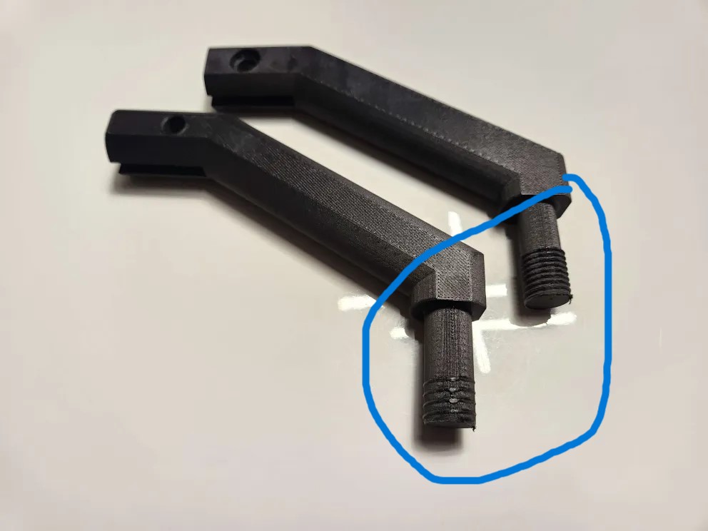
While I was adjusting the design back to its original state, I made sure not to “pre-order” any more hex bolts. It would be best to see what the printer produces and then find the appropriate hex bolts that fit, rather than just basing it off the model. Additionally, for the next iteration, I ensured that the holes were compatible with the tightening system already on my microphone for adjustability. Moving on to the third iteration of the second arm, I hope that I have the proper fasteners that work with my build, allowing me to soon focus on the aesthetic portion of the project.
2 Comments. Leave new
Hello Daniel,
Your remodel and prints look awesome. It was a great idea to wait to order hex bolts until the printing is done. I often run into similar issues because the filament shrinks or changes after the printing is completed. How was printing on the markforged? I have yet to print on it so I am curious how effective it is and how easy the use is.
Hi Daniel, I really liked how clearly you explained each step of your design and iteration process, it’s great to see how you’re using feedback from physical prints to inform your next steps. Your attention to tolerances and material fit is especially thoughtful. One question I had was about the foam used to reduce vibrations. Could you explain a bit more about how it will be integrated into the arm and whether you’ve tested its effectiveness yet? Looking forward to seeing how the aesthetic side comes together!