
For my main project, I chose to design and fabricate front suspension uprights for my 1965 Ford Mustang race car build. This vehicle is being prepared to compete in the GT1 TransAm class under the Sports Car Club of America (SCCA) General Competition Rulebook, which outlines a strict set of guidelines that must be met for eligibility. To create a car capable of performing at a competitive level, I made the decision to design a fully custom chassis and suspension system that leverages the rulebook to achieve the highest possible performance. Consequently, the stock front suspension and uprights were no longer applicable, leading me to develop custom uprights that optimize suspension geometry and support compatibility with a range of brake systems and wheel hub configurations best suited to my specific performance goals.
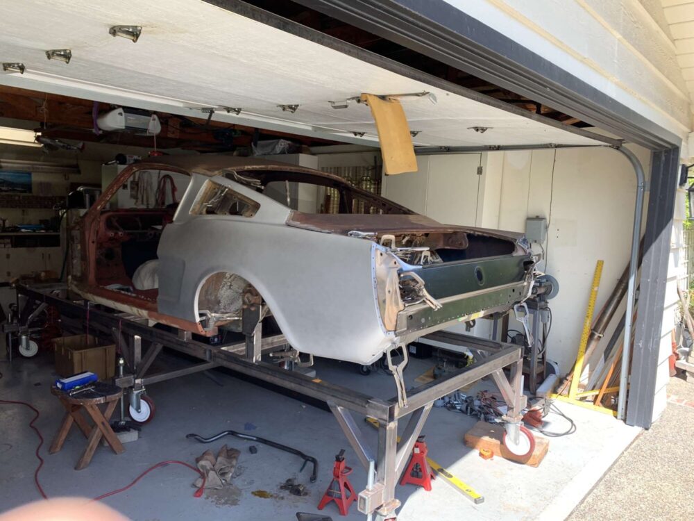
The figure below shows the 1965 Ford Mustang body shell mounted to a chassis table. This setup secures the car in a fixed position while using the chassis table as a precise reference plane for constructing and aligning the vehicle’s suspension components.
The design aesthetic I aimed for is inspired by aerospace engineering. This aesthetic is characterized by sleek, aerodynamic shapes and smooth, radiused edges. Designs that follow this style often incorporate geometric elements like triangles and grids, which are commonly seen in aircraft and spacecraft for their ability to optimize strength-to-weight ratios. Additionally, the aesthetic embraces a minimalist philosophy, with clean lines and features that serve a functional purpose, rather than being purely decorative. The materials used in this style are typically cutting-edge, chosen for their performance capabilities. For this project, I selected 7075-T651 aluminum for the uprights due to its impressive strength-to-weight properties, ensuring both durability and lightness. Any parts not made of aluminum was to be crafted from 4140 chromoly steel, a material known for its high strength and resistance to corrosion.
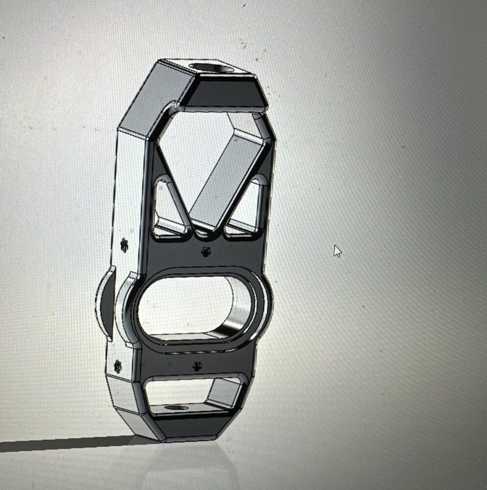
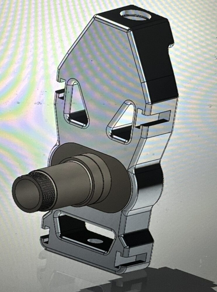
The image below presents an initial model of the upright, designed with this aerospace-inspired aesthetic. You’ll notice the smooth, radiused edges, as well as the triangular pocketing within the upright. These design choices were made to reduce weight while maintaining the necessary strength, thanks to the high-performance materials selected to prevent failure. The next phase of the design was to focus on modeling the spindle pin, which allows the wheel hub to interface with the upright. To proceed, I used the precise wheel mounting hub dimensions to establish the necessary bearing clearances and determined the vehicle scrub radius which are critical elements in the geometry of the front suspension. Additionally, I finalized the mounting interface for the brake calipers.
A contrasting approach to the aerospace aesthetic is a purely utilitarian aesthetic. This style emphasizes straightforward, efficient design that prioritizes manufacturability. By eliminating radiused edges and intricate geometry, the design simplifies the tool paths required for CNC milling, resulting in reduced machine time and faster production. The parts tend to be more robust in appearance and less polished, which allows for the use of more affordable, lower-strength materials without compromising the overall performance of the design.
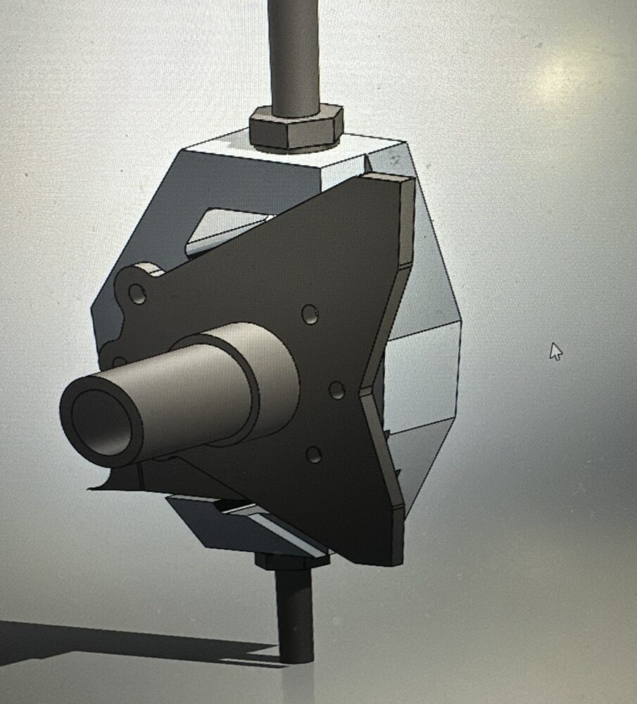
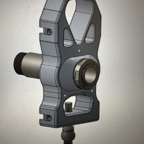
The image below shows a model of the upright developed with the utilitarian aesthetic in mind. Created in SolidWorks, this model features a simplified spindle pin interface with the wheel hub. Note the sharp machining lines and the absence of weight-saving pockets, highlighting the functional nature of the design. In this version, a mild steel spindle pin and 6061-T6 aluminum for the upright are utilized. Both of these materials are more cost-effective alternatives to the materials selected in the aerospace-inspired version.
The next phase in my design process involved establishing key parameters for the upright, including the locations of the upper and lower control arm mounting points, as well as critical suspension geometry such as scrub radius and kingpin inclination angle. For this build, I am using a 12-inch wide by 16-inch diameter front wheel, and I prioritized positioning the control arm pivot points as close to the inner edge of the wheel rim as possible. This configuration helps minimize leverage on the suspension components, reducing overall stress and improving durability.
To standardize the hub assembly, I selected a HOWE-style 5×5 wheel hub featuring a 2-inch spindle bearing. This particular hub design is a widely accepted standard in stock car racing, extensively proven across many NASCAR teams and supported by a range of aftermarket suppliers. With the hub selected, I was able to position it in close proximity to the lower control arm mounting point, which allowed me to minimize the scrub radius. This reduction in scrub radius helps limit undesirable jacking forces on the tire during cornering, ultimately enhancing vehicle stability and handling.
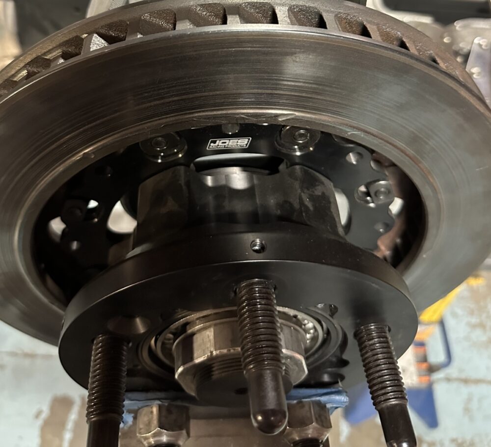
The figure below shows a 5×5 wheel hub manufactured by Joes Racing Products, equipped with a rotor mounting flange and a Wilwood brake rotor.
A primary objective in my design was to maximize adjustability within the suspension geometry, with particular emphasis on caster trail adjustment. Caster trail plays a critical role in the front suspension system of a vehicle, directly influencing steering stability and the responsiveness of the vehicle to driver input. This parameter can be tuned by altering the relationship between the front axle centerline and the kingpin axis centerline. To achieve this, I developed a system using removable offset keys that insert into the upright body and securely capture the bearing pin. By swapping these keys with alternatives featuring different offsets, the position of the bearing pin can be shifted forward relative to the kingpin axis, allowing for fine adjustment of the caster trail.
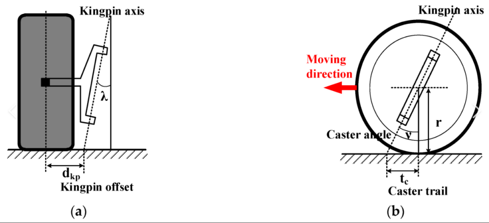
The figure below visualizes two key geometric concepts. On the left is the vehicle’s scrub radius (dkp), defined as the lateral distance between the tire contact patch center and the point where the kingpin axis intersects the ground. This dimension can be tuned by modifying the upright geometry or adjusting the wheel hub mounting flange offset. On the right, the caster trail (tc) is shown, which is the longitudinal distance between the spindle centerline and the ground contact point of the kingpin axis and another critical factor in steering behavior that is directly adjustable using the removable key system.
With the design parameters clearly defined, I proceeded to refine my preliminary CAD model to meet the specific geometric requirements. During this stage, I identified an opportunity to simplify the brake caliper mounting system by eliminating the need for a separate bracket. Instead, I integrated T-nut slots into the upright to secure the brake caliper directly. This approach offers adjustable caliper positioning, which is typically managed using shims between component interfaces. As the brake pads and rotors wear over time, the T-nut system allows for quick and precise repositioning of the caliper, streamlining maintenance and enhancing overall serviceability.
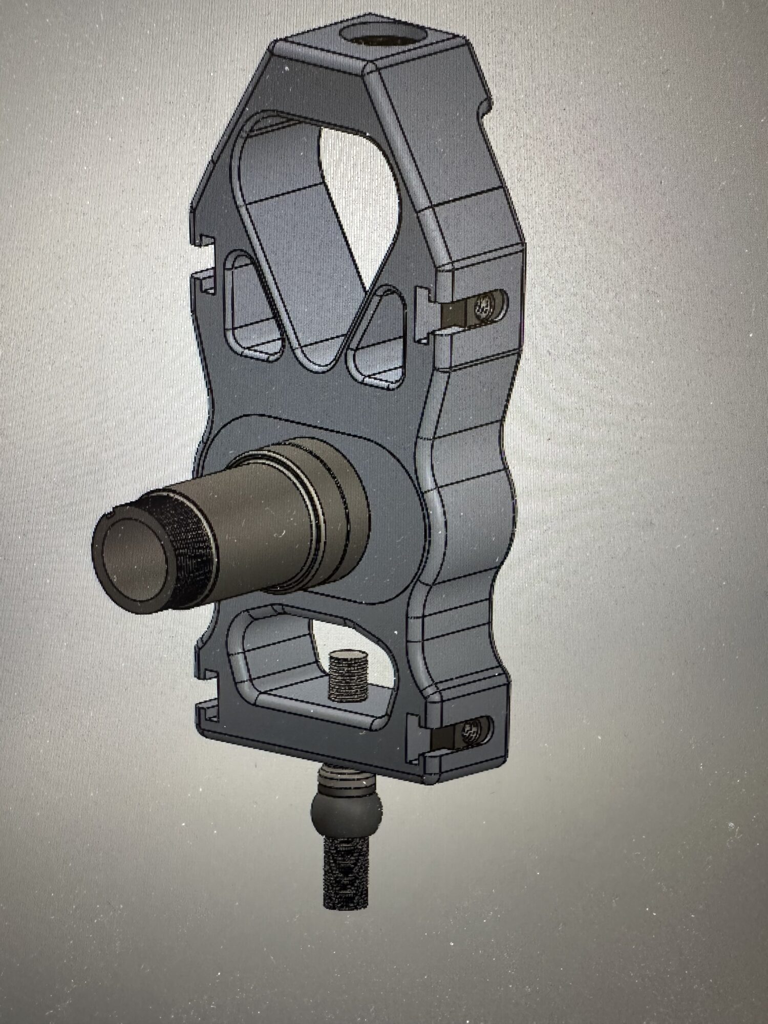
The figure below shows the revised upright design featuring T-nut mounting slots for both the Wilwood brake caliper and a custom steering arm. The image also highlights the fully modeled spindle bearing pin, complete with centered caster trail adjustment keys.
Advancing to the next phase of the design process, I remained committed to the aerospace aesthetic by focusing on reducing weight while maintaining structural integrity. To meet this objective, I selected 7075-T651 aluminum for the upright body and adjustment keys, due to its excellent strength-to-weight ratio. For the spindle bearing pin, I opted for 4140 chromoly steel, as this component is subject to significantly higher bending loads resulting from intense braking and cornering forces.
Following a combination of hand calculations and Finite Element Analysis, I confirmed that the use of these high-strength materials provided sufficient margin to further pocket the upright body without compromising durability. This allowed for additional weight reduction while maintaining a safety factor of 1.5, consistent with industry standards in both motorsports and aerospace applications.
The figure below shows the final design, ready for manufacturing. This iteration incorporates expanded pocketing of the billet aluminum to reduce mass, along with fillets and radiused edges designed for efficient production using 3-axis milling operations.
2 Comments. Leave new
This is so cool!. I learned a lot about cars and racing from this post. I think it is amazing that you have a project car. The diagrams and CAD were very helpful in understanding what is going on. I was wondering if maybe you could do renders or screenshots on the computer instead of some phone pictures. overall amazing job
Hello Xander, thank you for the comments. It is great to hear that the technical aspects of the front suspension geometry make sense to my audience. In the future, I do think that higher resolution renders would be a great idea to improve the appearance of the post.