
This post will be purely dedicated to the logistical and technical work that I have done for my final project. I will cover the manufacturing process associated with my artifact which I have know titled the “Dynamic Light Sculpture” or DLS. I will also discuss my bill of materials and electronics.
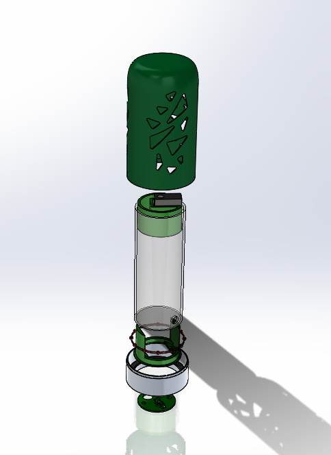
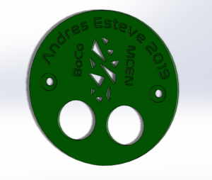
The system is compromised of 6 manufactured parts, the bottom housing, a structural tube, the outer rotating green shell, the servo motor housing, and two parts compromising the bottom cover. The exploded view below provides a better description. I have not yet printed the bottom cover successfully as the level of detail is higher than what I set the resolution to in my first attempt, I engraved my name and other details using a font inspired from a retro NASA logo.

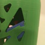
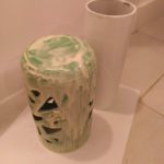
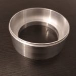
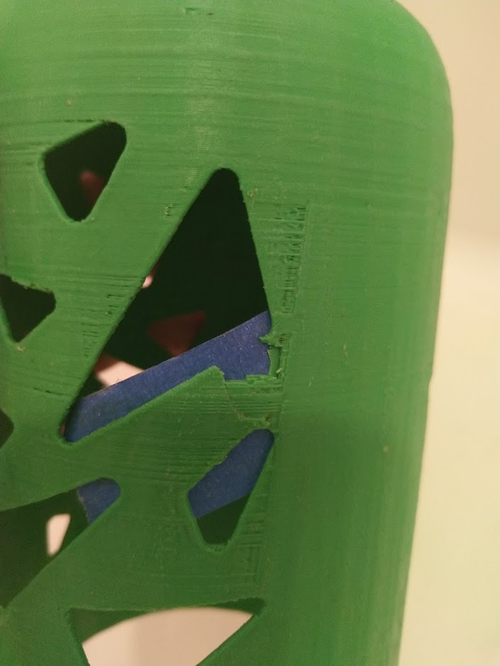
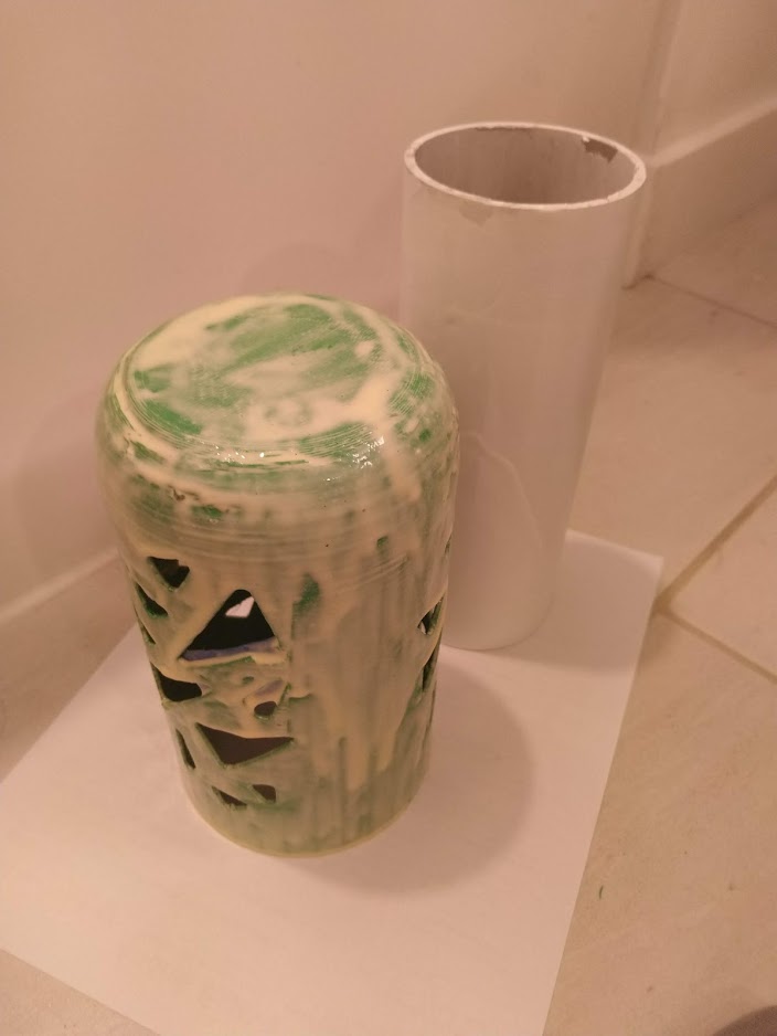
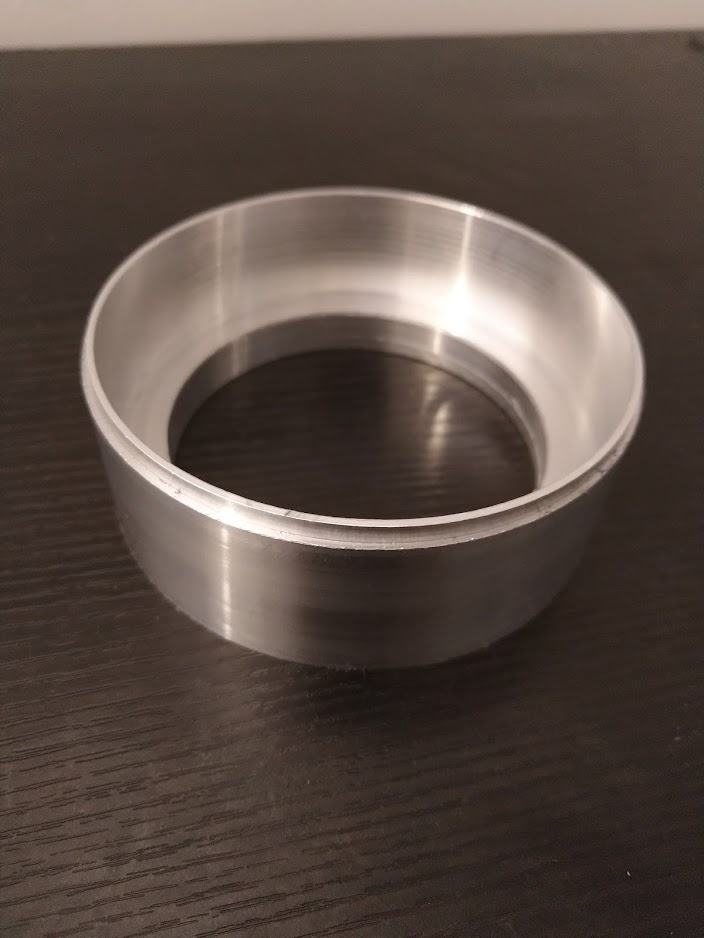
Once I had conceived an idea and made a CAD model the manufacturing began. I used three methods in the making of the DLS, I started by turning a stock 6061 T6 Aluminium tube into the shape of the base. This part (DLS_01) is the backbone of the mechanics that will ensure a smooth operation when rotating, the technical drawings specified 5 thousands of an inch as tolerance for the inner diameter. Perhaps the most complex part is DLS_02 and this is where the second method of craftsmanship comes in. DLS_02 was made thanks to the marvels of 3D printing thus the outer rotational casing was made after 17 hours on the heated bed from a green PLA by FDM (Fused Deposition Modeling) printing. The remaining manufacturing method used is perhaps the most primitive and artisanal as I used my hands to seal any holes with glue and later sanded it smooth. I am yet to add a finishing coat of paint as a last minute decision.
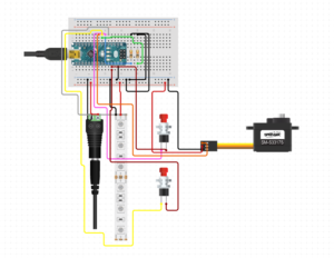
As far as electronics go everything is powered by a square 9V battery and controlled by a RaspberryPi Zero. For motion, I am using a full rotation servo controlled with digital PWM (Pulse Width Modulation). As far as lighting is concerned the LED’s are also controlled with PWM from the computers GPIO pinouts (General Purpose Input Output). The circuit diagram below is what I have on a solderless breadboard however I soon have to find a more permanent solution.
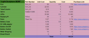
Like all projects and this one is no exception there are finances associated with it. Starting the semester I did not have a budget I wanted to meet however I wanted to spend something roughly equivalent to a textbook since we don’t use one in this class. I was surprised to see how quickly I spent money for the project and in the end I spent a little more than what I would have liked nonetheless I am really liking the outcome and I am sure I will look back at the DLS years from now as a priceless design and a memory of my time in university and Boulder. My bill of materials added up to just below $150.
References:
online circuit diagram maker: https://www.circuito.io/
Nasalization font: http://typodermicfonts.com/ or https://www.dafont.com/nasalization.font
9 Comments. Leave new
If only you were able to do a high quality print to reduce those holes in the case but overall this came out looking awesome.
This looks so professional. I would expect to see something like this in the store! I only wish that the light source was a little brighter to give a more pronounced affect.
I like how you used RaspberryPi and still pull off a great project. I should have gotten your feedback on my projects during my own process. Great work!
I like how you used the RaspberryPi in your project and still pull it off a great project. I think I should have work with you to get feedbacks from you.
It is exciting to see how well your project turned out! All the work that you put into this project definitely paid off. You used the pantone color of the year…have you thought about changing the light every year to match the color of the year?
Hey Andres I really like the colors you used in your project. The shapes are also unique as well as the functionality of the project. I hope you can fix the switches sometime in the future. It would be cool to somehow improve the lighting effects. Maybe increase the brightness? Overall good job.
Hi Andres,
Great work on your project. You look you have put a lot of efforts on making it. I like the final results especially the colors. great work.
Andres, I am really impressed with your project. I cant believe that you actually 3D printed the case because 3D printing is such a pain. I am also impressed that you went into the machine shop because we all know how terrible that place is. I was wondering how you decided to do the pantone colors of the year. I didn’t even know that existed.
I really like the blend of colors you have! The blue and green reminds me of tropical rain forests, and I think the spinning is at the right pace to feel calming without being uninteresting. You seemed to put a lot of work into iterating your design, and that seemed to benefit it.