
Water Clock
Introduction

For this project, I will be developing a clock/timer that is controlled by droplets of water. The idea here is to incorporate water and electronics and invoke that sense of uneasiness, yet also provide the calmness of falling water. The device will consist of a white or clear acrylic body that contains a shallow plastic bowl. From the bowl, the water will be pumped up about six inches and fed into a spout. The water will then fall onto a force sensitive resistor (FSR). An Arduino Uno will be used to detect the change in voltage across the FSR and tick a counter to keep track of time. The time will then be displayed on an LCD screen. All electrical components will be mounted to the acrylic body of the device and covered with another sheet of acrylic.
I will be targeting Apple’s minimalist design aesthetic using white colors with sleek transitions and curvy lines. Everything in their products are customized for the specific applications and Apple even designs innovative manufacturing processes to facilitate the fabrication of the design. Their products look clean, and although it will be difficult to mimic the curved lines, the white color and simplistic design will hopefully be enough to tie it all together.
I was initially thinking of using a cylindrical container to hold the water. The pump would fill the cylinder up and as the height of the water changed, the pressure in the cylinder will change which could be detected using a pressure sensor. As the pressure changes, the clock on the Arduino would then tick. There are a few problems with this. First, the change in static pressure would be really small, and therefore, it would be difficult to find a sensor with the appropriate resolution and accuracy; it could be possible to use a proximity sensor to detect the change in height, but I decided to steer away from this option. Secondly, the user would have to “reset” the clock by dumping out the water in the cylinder; there are many ways around this such as using a valve, however, I am trying to keep the design as straightforward as possible.
Inspiration
At the beginning of this course, I knew I wanted to make a clock of some sort. I was initially thinking of using a purely mechanical design to add a twist to an analog clock. I then started thinking about incorporating water. I brainstormed a few ideas and a few aesthetics. I landed on the concept of using falling water to tick the clock. This led to more ideas such as using a water wheel to turn an analog clock, but I decided I wanted to use water and electronics. So, I went with a digital clock, a sensor, and a pump. All of this would be controlled by an Arduino.
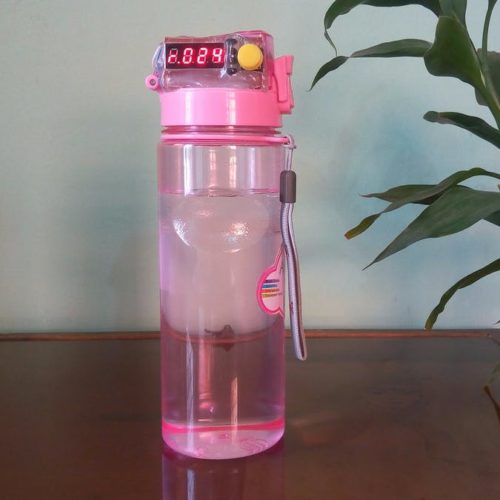
I found a few hobbyist projects online that were using a similar concept. One of which is a water bottle that can keep track of the user’s water intake. It uses an ultrasonic proximity sensor to detect the change in height of the water and displays the volume on the segment display. I did not find any projects that used water to tick a digital clock, though. As far as I am aware, it is an original idea.
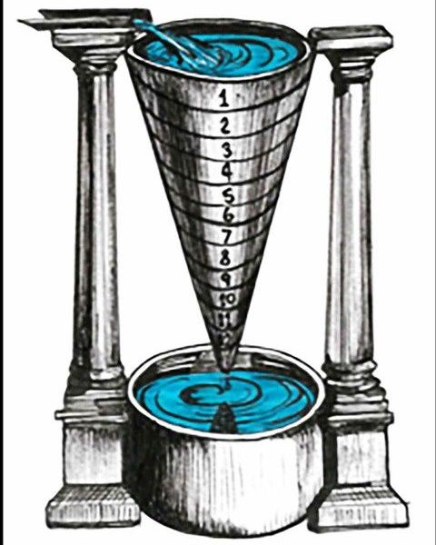
With that said, water clocks have been used all the way back in the 16th century B.C. With these devices, a controlled flow rate of water into or out of a reservoir was used to keep time. There are markings on the container to indicate how much time has elapsed since the container was full or empty. They are known to be invented in Athens, Greece, and used to time out harvest seasons and things of the like. The technology exploits Torricelli’s law of water escaping a container through an orifice.[3] As the height of the water decreases, the speed, and therefore the volumetric flow rate of the stream, changes with time. There is a lot of knowledge of fluid mechanics and engineering implemented in these devices.
Vision
The clock is going to be desk size and will have an aesthetic that matches the image in Figure 1. It will be minimalistic and white in color. Hopefully the design will create a calming sound similar to a gentle waterfall. The device will keep time to within 5 minutes. It will have an interesting look and catch your attention from across the room.
Design
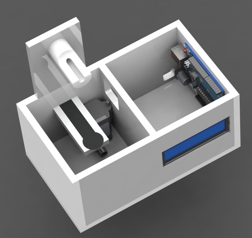
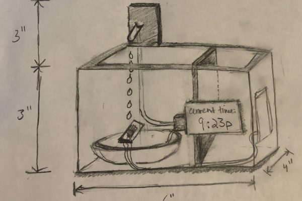
The device is going to be about six inches in length, four inches in depth, and about six inches in height. The acrylic body will only stand about three inches tall. The spout will be 3D printed and bonded to the acrylic tab that sticks out of the enclosure. This allows the water to gain enough potential energy to trigger the FSR but also makes the water visible over the wall of the enclosure. Additionally, the FSR will be mounted to an acrylic tab that is cantilevered from the edge of the wall. Below is a rough sketch of the general concept.
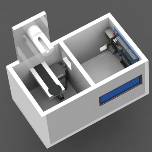
The acrylic will be cut on the laser cutter. Each of the acrylic pieces can be solvent welded together to create a strong seal. If the seal is water-tight enough, there will not be a need for a bowl or reservoir, and the water can be stored in the left compartment along with the pump. In the right compartment, the electronics will be stored. The wiring for the sensor and power cable for the pump will be routed up above the water level and into the electronics compartment; from there, they will be routed out through a hole in the acrylic on the backside of the device. The LCD screen will be mounted in the front wall of the enclosure.
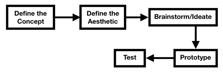
A diagram of my design process is below. Due to the budget and time constraints, my process will be pretty linear. The idea here was to keep the design as simple as possible, while budgeting my time wisely for manufacturing. I have decided on what concept, what aesthetic, and I will be manufacturing in the coming weeks.
Materials
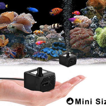
The acrylic parts will be manufactured out of 1/4″ thick sheets. The following pump will be used. It is designed for aquariums and can supply up to 50 GPH. It has an adjustment knob to change the flow rate. The pump has suction cups on the back that will make it easy to mount in water.
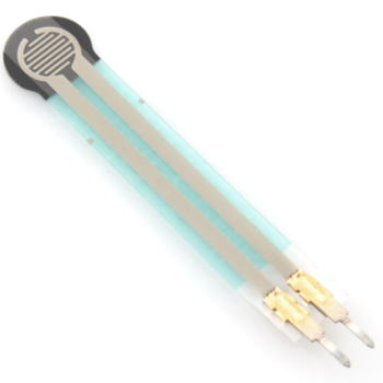
The following force sensitive resistor will be used. It can detect anywhere from 0 to 10 kg. To ensure the impact force of the drop on the sensor is sufficient, the volumetric flow rate of the pump can be changed to alter the mass of the droplet/stream. As the gravitational potential energy gets converted into kinetic energy, the velocity of the droplet will increase, therefore increasing the change in momentum of the droplet and in turn increasing the impulse or impact force on the sensor.
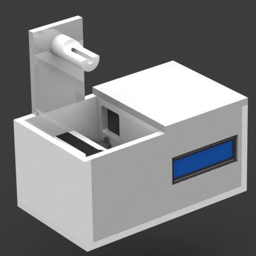
An Arduino Uno and breadboard circuit will be used to monitor the voltage across the sensor. It will then tick the clock and will display it on an LCD screen. Theoretically, this device could be used as a timer or a clock. Below are some preliminary CAD renderings of the device.
Challenges and Stretch Goals
It is going to be difficult to achieve the curvy lines with the acrylic sheets. It may be possible to machine the acrylic and break the edges, however, even if the rounded edges cannot be achieved, the design should still fit the targeted aesthetic. Another challenge is going to be setting the flow rate of the pump to output enough mass to actuate the sensor. As a stretch goal, I will add a strip of LEDs to add to the aesthetic of the device. The RGB LEDs could then be independently controlled so the device can be used with or without the lights. If implemented appropriately, the light could be refracted through the water, so perhaps they could be mounted at the bottom of the reservoir.
Conclusion and Design Metrics
The project will be successful if it can measure the water dropping on the sensor and tick the clock. The device shall contain the water without the water leaking into the electronics compartment, potentially ruining the electronics. The device shall be small enough to fit on a desk. If the device fits in with the theme of the devices in Figure 1, then it will have met its aesthetic requirements. I have not completed any manufacturing and am in the process of procuring materials. If you have any suggestions or any white acrylic laying around, please let me know.
6 Comments. Leave new
I really love your final project idea. I think the logic and aesthetic behind it are very interesting. I personally have not heard of a water clock before, and would love to see how yours turns out. If I may suggest something, I would say adding few drops of food coloring to change the color of the water would make it look nicer without changing the fluid properties.
Thanks, Abdulrahman! I will definitely take that into consideration.
Hi Danny, I don’t think the LEDs are necessary for your aesthetic, in fact, the Apple aesthetic is so simplified and clean that adding excess LEDs might ruin it in my opinion. Also, if you are worried about the combination of elctronics and water, and how water might affect your microcontroller I highly recommend adding a small bag of silica gel (dehumidifier) to your electronics section. I think the acrylic divider will keep doing a good job of keeping actual water droplets out, but adding silica reduces the risk of humidity ruining the electronics.
Thanks, Fiona! That’s a good idea.
Hey Danny,
This is a really interesting idea, I hadn’t heard of a water clock before this, despite it being ancient technology! I think some points for you to focus on, as you mentioned, will be avoiding an overly box-like appearance. Also to consider, are additional water-proofing measures, or very thorough testing of the water tightness of the solvent bonded acrylic. I’d be hesitant in being confident that alone will be enough to keep the electronics safe.
Thanks, Thomas. I will be mounting the electronics to the walls of the electronics compartment so hopefully that keeps the electronics from getting exposed to the water in the event of a leak. Worst case scenario, I will add a bowl of some sort to contain the water.