

Background:
For my project, I want to create a maximalist cantilever rear suspension setup for an SN-95 Mustang.
Pre-manufacturing progress so far:
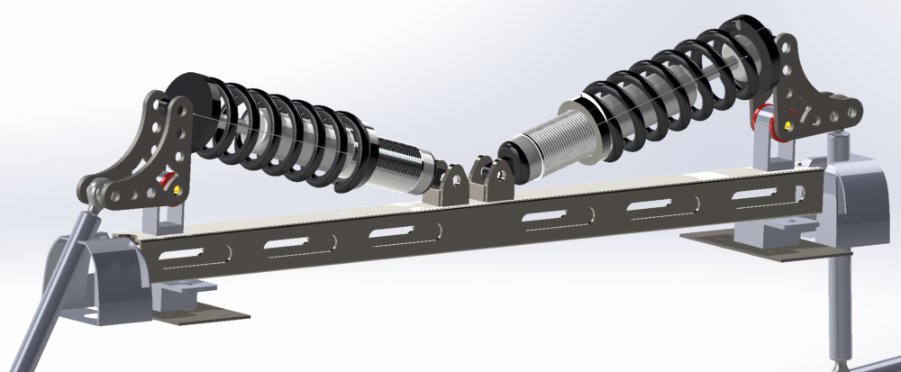
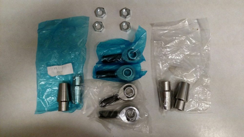
So far I’ve designed most of the suspension in CAD (there will be minor changes to the design depending on how the manufacturing process goes and if I have to do anything differently that I didn’t think of or account for in CAD). I ran some FEA simulations on the bell cranks and came up with a design I’m happy with and have gotten those laser cut from the company SendCutSend. I have also gotten the necessary hardware to mount the bell cranks, the bushings and the material/parts for the pushrods. I forgot to take picture of the metal stock most of the time.
Manufacturing progress so far:
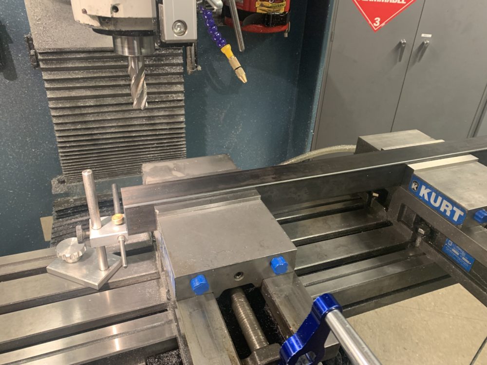
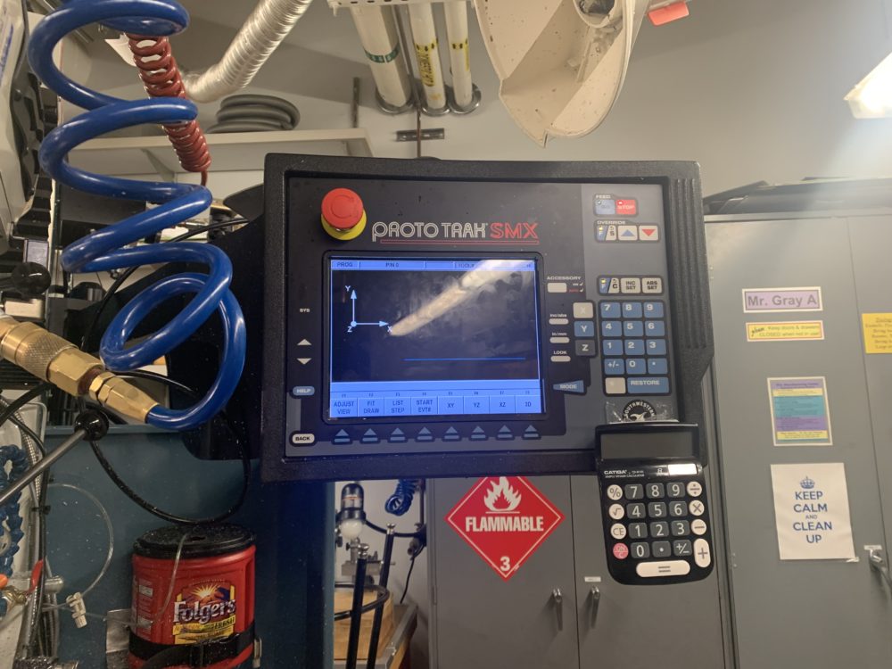
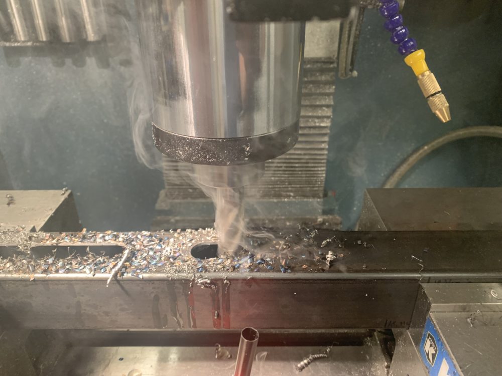
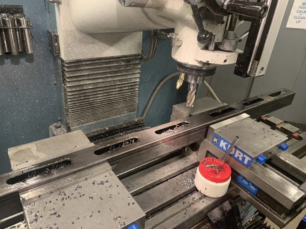
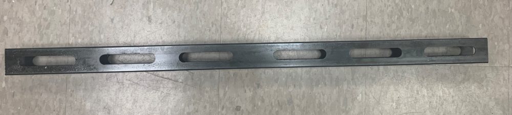
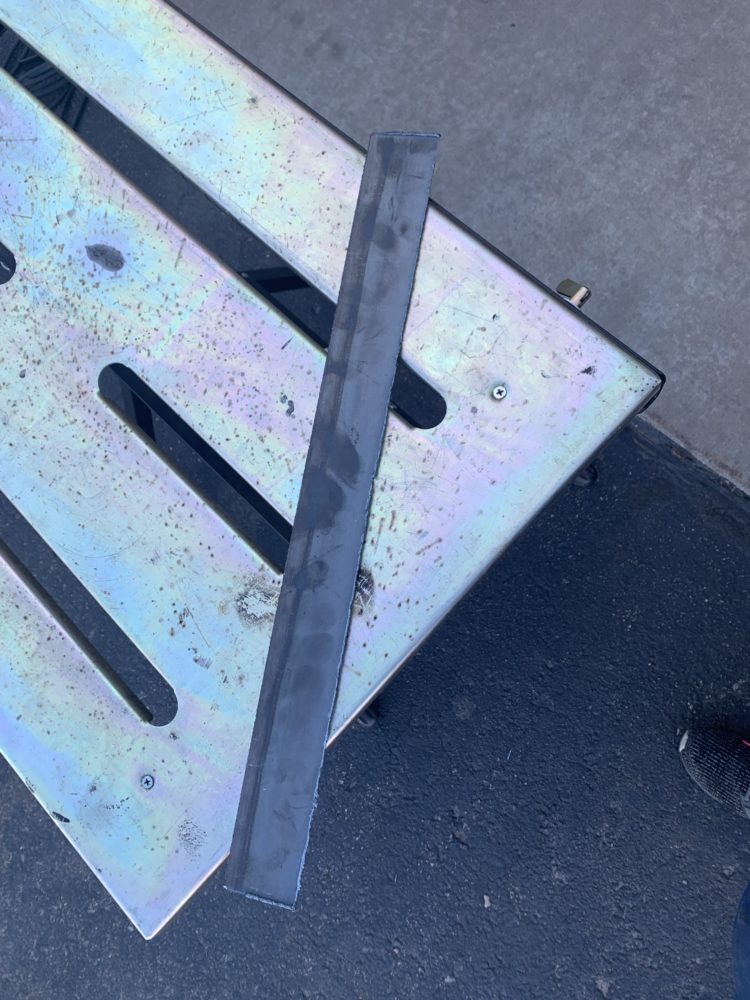
I started the manufacturing process by test fitting the scrap square tube I found that I’ll use as my crossbar. The crossbar was very close to the length I wanted, but needed to be shortened by about 1.5in. I cut it down and squared the ends at the ITLL machine shop. Then I milled out the slots in the crossbar using a simple CNC program on one of the shop’s mills (thank you Elvin ??).
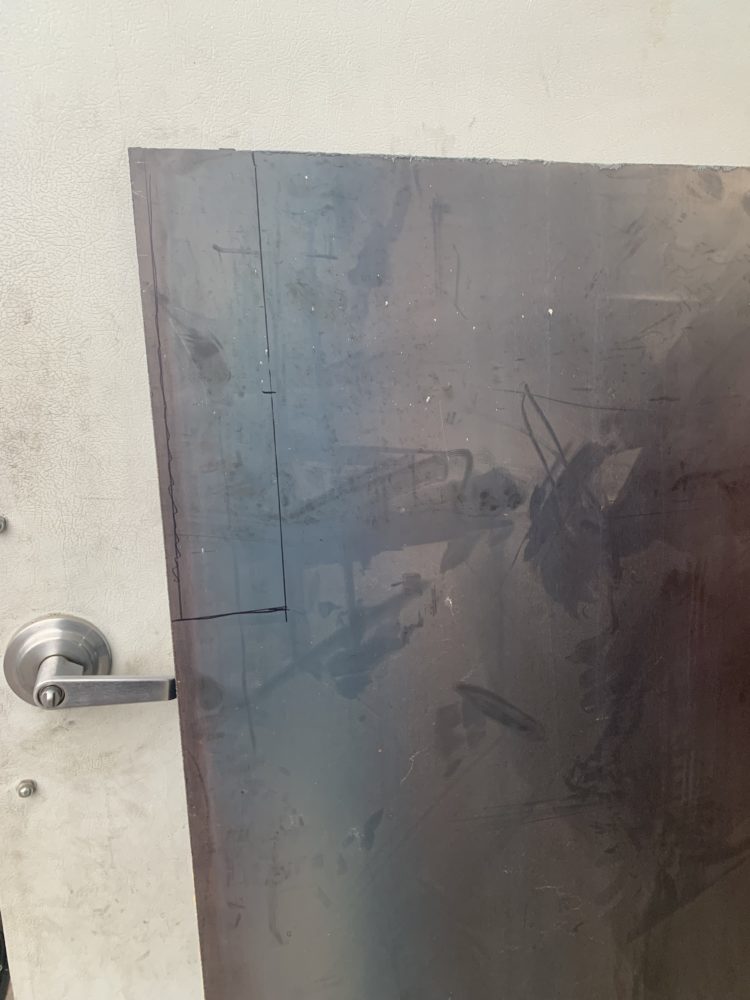
The crossbar cannot simply be welded to the body of the car because the body is made of very weak and thin sheet metal. To remedy this problem, I need to weld plates onto the body and then weld the crossbar onto the plates. This spreads the force out onto a larger area to keep the sheet metal from deforming and fracturing and makes the welding process easier due to the thickness differences between the two metals being lessened. I determined the dimensions I wanted for the plates using the car and crossbar and plasma cut those out. The crossbar is meant to also be a structural member of the car and is meant to stiffen the chassis so I chose to place the plates right next to the shock towers and right above frame rails are so the crossbar will be welded to the strong frame rails of the car and stiffen the chassis. I plasma cut the plates out of a .125” sheet of steel my dad had (I think, don’t really remember). I then cleaned up the edges and rounded the corners of the plates using grinders.
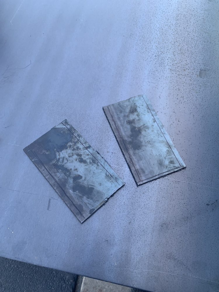
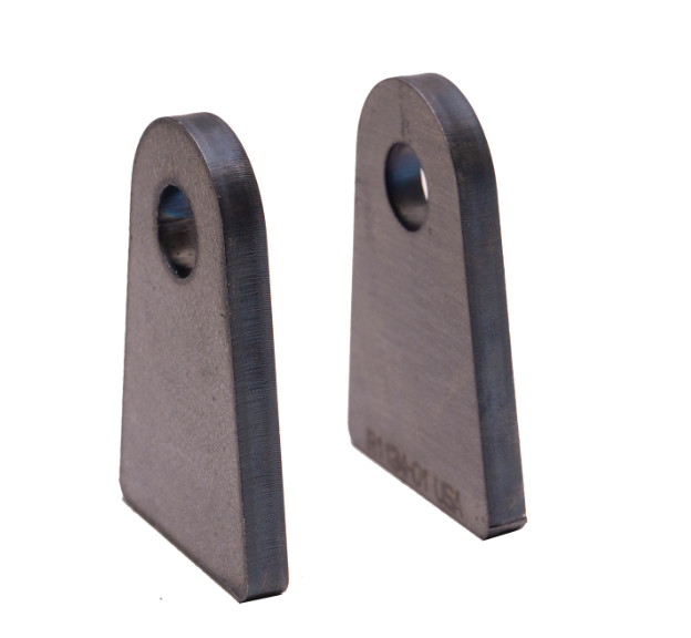
In an effort to get this project done within the time allotted (not sure this is going to happen), I chose to add flanges that connect the crossbar to the plates so the suspension has the modular functionality I’ve been designing for and because welding the necessary parts onto the crossbar with it in the car would have been very hard/impossible in some places. Honestly this design is quite ugly in my opinion but it will help me try to finish this project in time and I’ll redesign after this class is over to be more functional and pretty.
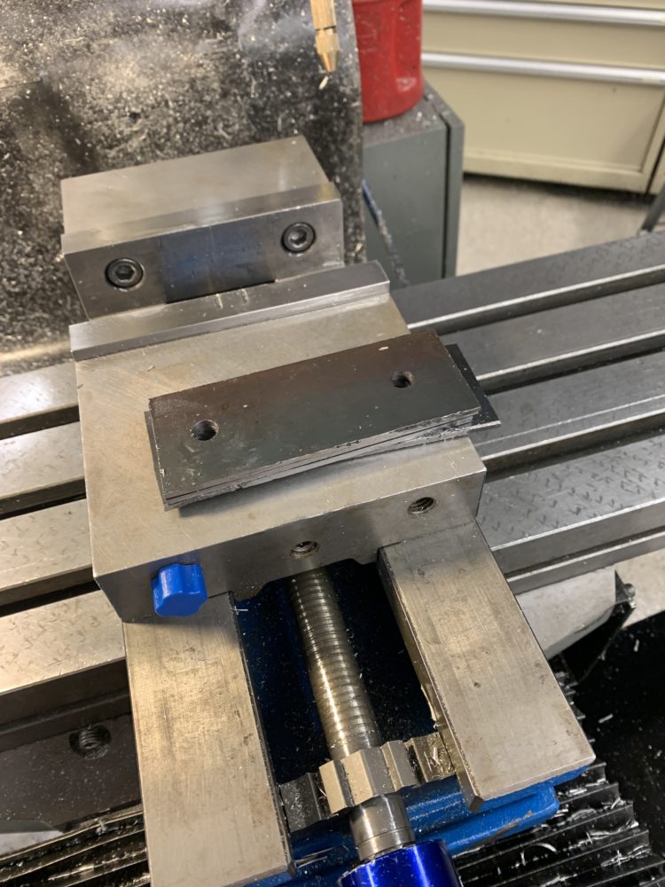
Again, I decided on the dimensions I needed for the flanges and plasma cut those from the same sheet of *thickness* steel used for the plates. I cleaned up the edges again then brought them to the ITLL machine shop to accurately drill the bolt holes using a mill.
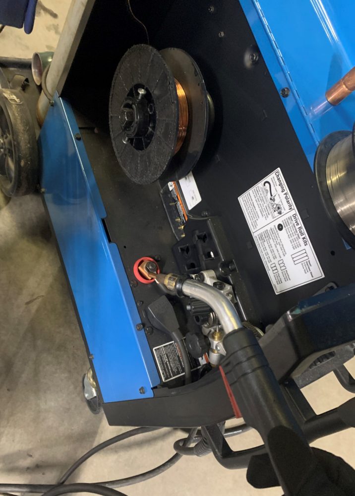
MIG welder broke 🙁
Once I was able to get the car on the lift, I removed the rear tires and coilovers. I don’t really have the money to buy new coilovers chosen specifically for this project right now so my plan was/is to use the coilovers from this car (not the greatest solution).
Also, for a bit of context, the car this suspension is currently going into has a live rear end and coilovers. I’m designing this suspension for this rear end but will redesign/remake at least the pushrods later due to the car getting an independent rear suspension (IRS) soon. Because the current rear end has coilovers, I can reuse the shock tabs that the coilovers use to mount to the rear end for my pushrods.
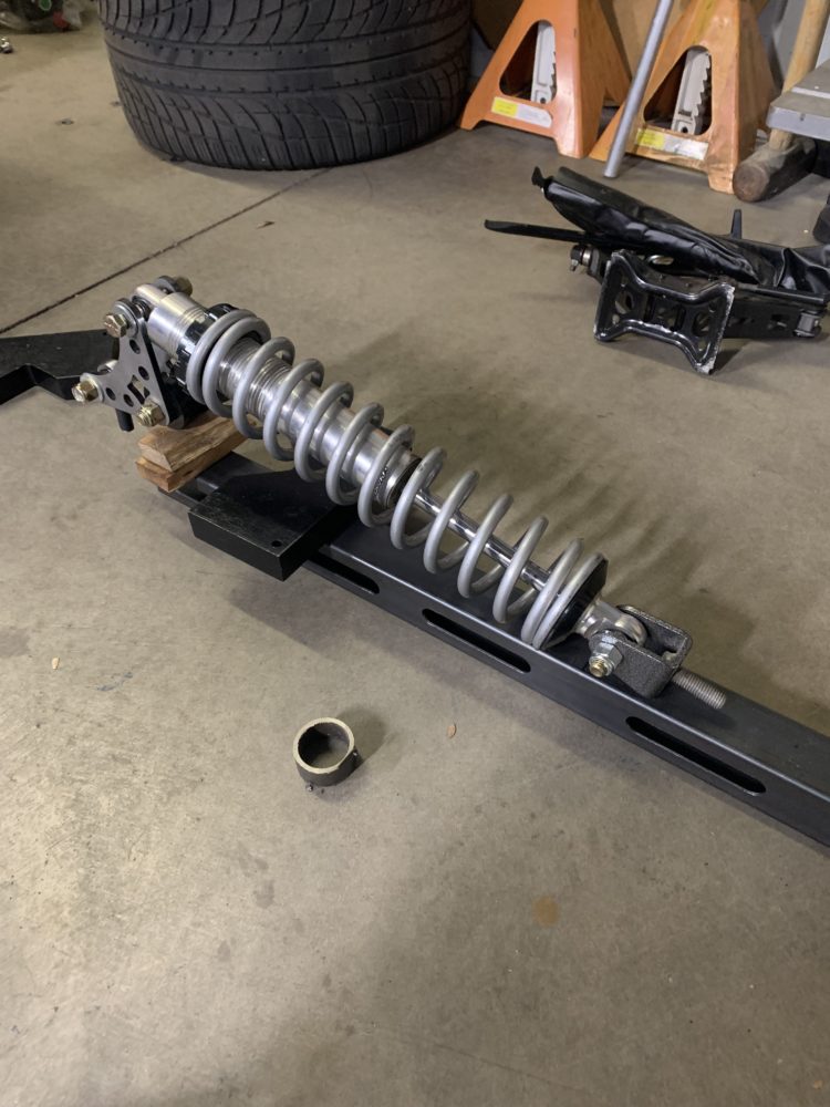
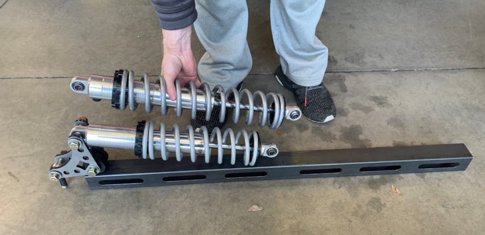
After a quick mockup, I realized that the coilovers that were on the car already were way too long for my design (18.875” max extension with a 14” spring, max extension of ~16” is around what I want). I found some 10” springs laying around and put those on the coilover shock. These springs shouldn’t really be used with this shock but it’ll work for demonstration purposes, probably. The shock still has around 2-3″ of travel out of its total of 5.875″ (I think) of travel. The shocks are not gas charged so I could just push them down to fit the spring which made things easier for me.
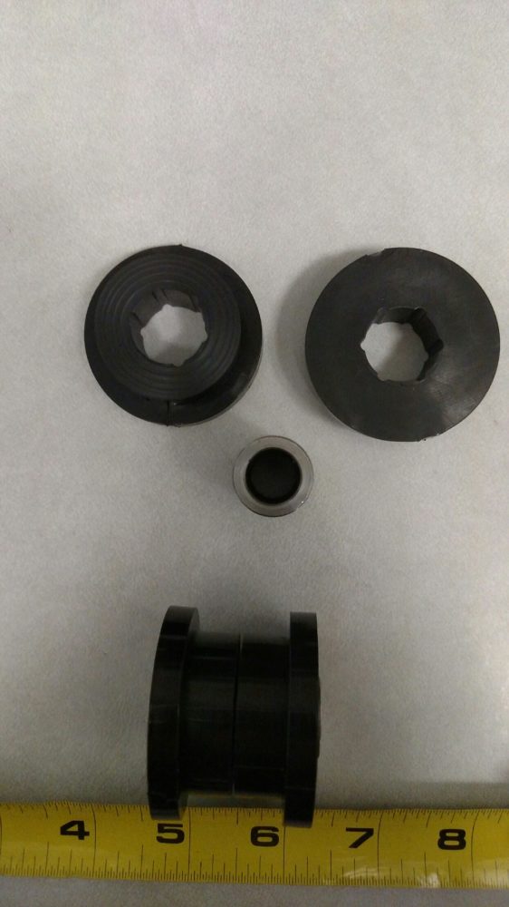
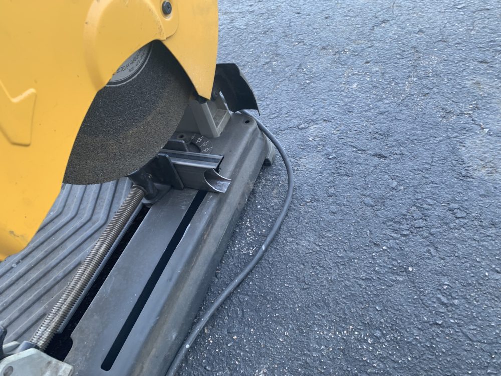
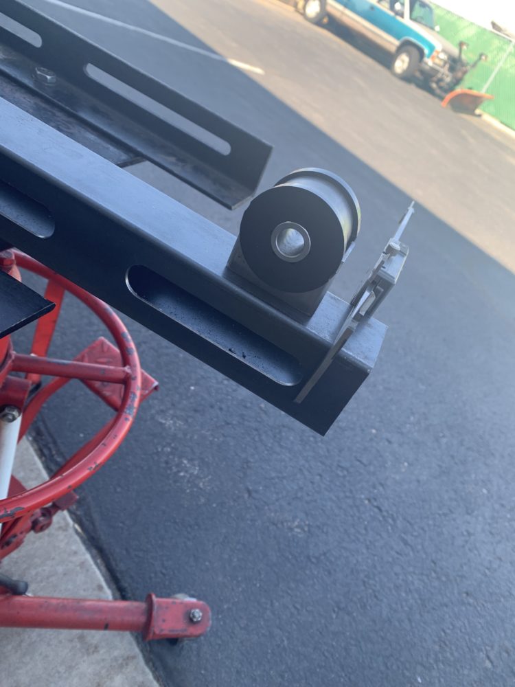
After that, I moved on to making the bushing tube and its standoff. I cut a bunch of tubes as close to 1” as I could and chose the two best ones to move forward with. After a ton of grinding and squaring, I had to bushing tubes that worked. I’ve grown accustomed to the precision and ease of using the mills and lathes at school when making parts. Making parts with chop saws, manual plasma cutters, grinders, etc. takes much longer and requires way more post-processing, at least when I’m making the parts. I didn’t really account for this when planning this project. In the below picture, the left bushing tube is a shortened and cleanup one while the right bushing tube has had no post-processing done to it.
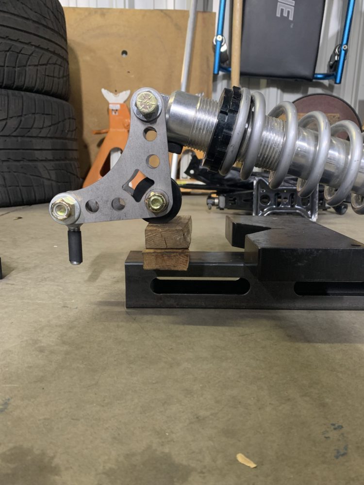
I then got the stock I am using for the bushing standoff, cut it to be larger than it needed to be and c-notched them with a hole saw and drill press. The bushings are slightly too short so the bell cranks will be rotating on the outer polyurethane housing right now. I’m just going to go with it and see how that works.
After another mockup, I decided on the height the standoffs should be and cut those down.
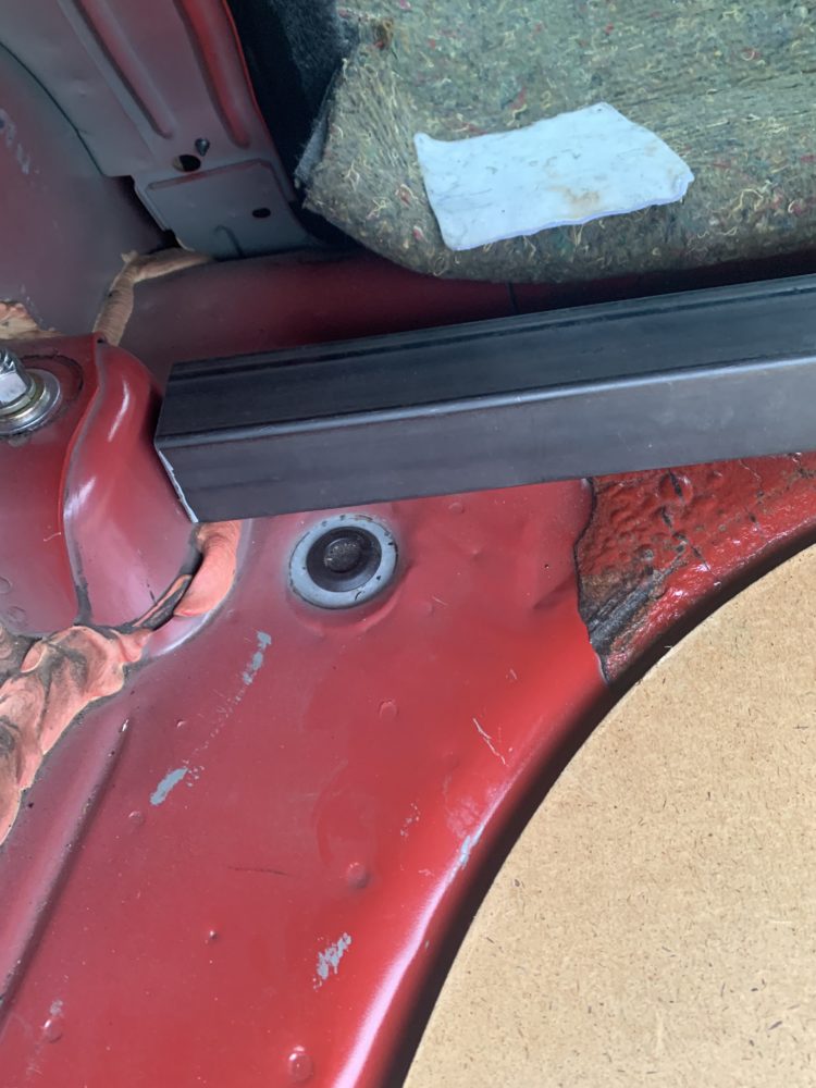
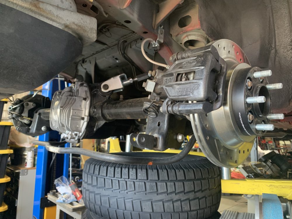
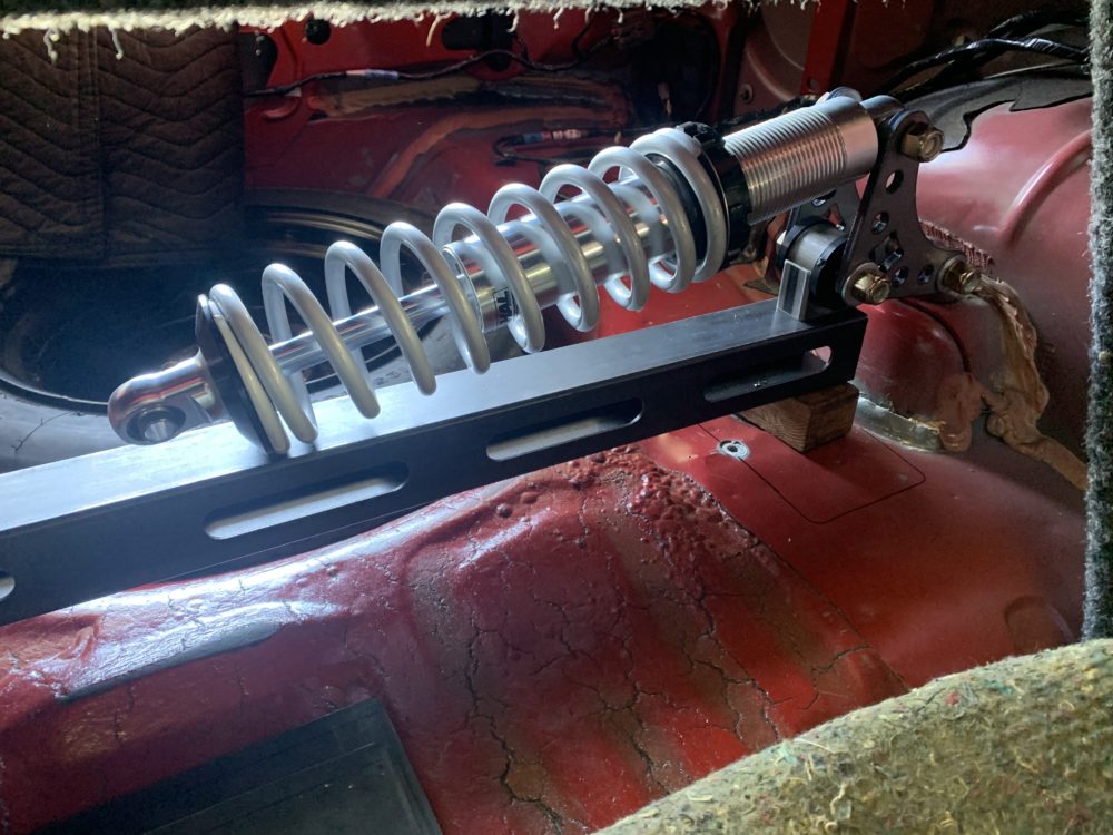
This is a mockup of the suspension in the car currently (just one side).
There are still many, many things to do. I’m just kinda going with the flow and changing manufacturing plans when I run into problems so I’m not really sure what I’m doing next. A lot of the next steps is just welding stuff together correctly. I doubt I’ll get the project done this weekend and in time for the next blog post but we’ll see.
1 Comment. Leave new
This is such a cool project and I love seeing the progress you’ve made, there is a lot of engineering and problem solving work that you have done but haven’t mentioned; would love to hear more about what kind of modelling or math you had to do to make this work.