

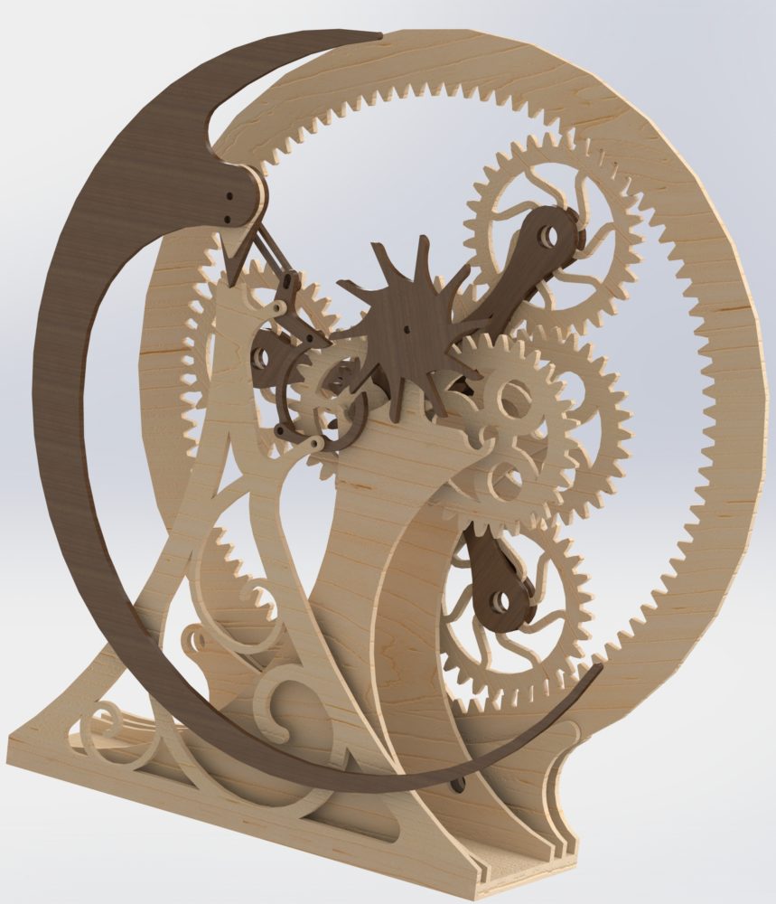
 I have finalized my CAD and begun work on actually fabricating my escapement mechanism. I spent several hours working on the aesthetic of the gears, pendulum, and the front panel so that they would all appear cohesive within the larger construct. I decided to include both more traditional gear designs as well as more organic features. I did this to pay homage to the antique clocks and kinetic sculptures from which I drew inspiration. Since I am using the large planetary gear system as a background for the design, I decided to follow a similar contour with the pendulum to help provide contrast. It took many iterations before I was happy with the way that everything looked for the overall design, but since I don’t plan on iterating the design after it is fabricated too much, I wanted to ensure that I was happy with it before I started using materials.
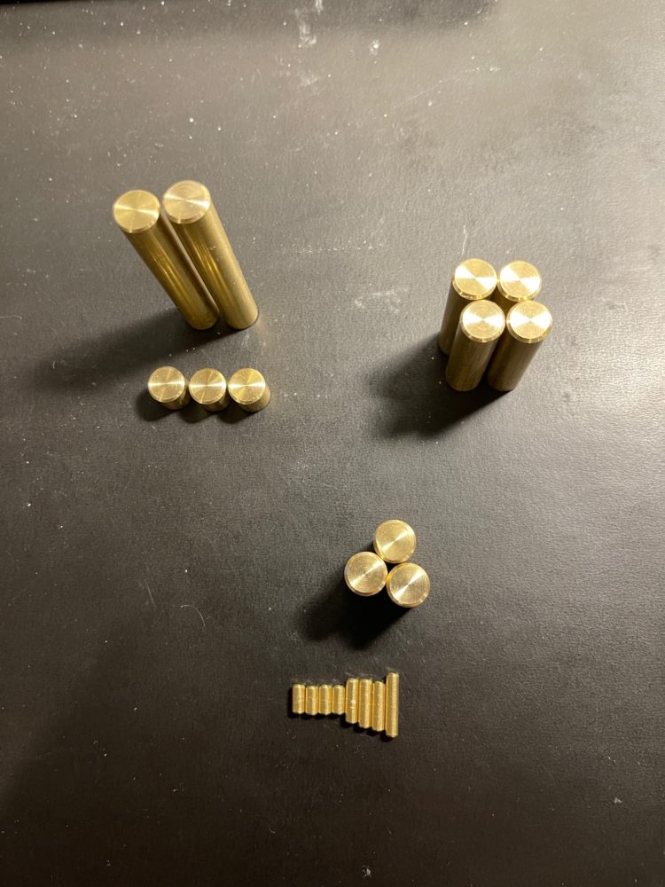
I have started fabrication with what I expected to be the most time constrained part of the project: fabricating the brass elements. I had the most concern over this for several reasons. This includes aesthetic and practical concerns. I was primarily concerned that I wouldn’t be able to fabricate the necessary brass pieces in time if the machine shops on campus were busy or if the process of parting the rods from my stock material was more complicated than I expected it to be. My second concern was with finishing the rod segments so that they added to the overall aesthetic that I was trying to achieve instead of potentially detracting from it. However, in my work since my last post both of my fears have been alleviated. The process of parting the rod segments from the stock material was relatively easy on a bandsaw for the 3/8″ pieces though I struggled with the 1/8″ segments and had to use a Dremel. This resulted in rougher cuts and slight marring on the sides of the rods. I do not believe this will impact the overall aesthetic as the sides of the rods will be hidden in most cases. After I separated the rods, I was able to turn down the faces on a lathe and add a chamfer. This made a very appealing finish that will stand out against some of the wooden elements while adding to the overall aesthetics of the piece. I have discovered some rod lengths are incorrect, so I will need to machine one of two pieces, though this shouldn’t take too long.

In the next few days I plan on laser cutting all the components of my design that require it. I have received all the material that I will need to fabricate my design. I expect the process of laser cutting the materials to take 1 hour. If all goes well, assembly should also be relatively fast. At this point, I think I will stick with the bare material instead of applying a finish, though I may change my mind when I see it assembled. I am also attempting to avoid including adhesives for the brass-wood interfaces if possible. I want to make the final product look clean without any noticeable adhesive marks. As such, I plan to make the interfaces compression fits, though I have CA glue should it be necessary.
As of right now I am on track to finish the project. I plan on cutting the components and assembling them at the end of the week to allow myself time to adjust anything that needs it.
4 Comments. Leave new
Hi Palmer,
This is a really cool design. I think the use of different shades of wood really brings the design together.
Hi Ali, thank you, that was the intent! I really wanted to be able to highlight some of the gearing systems while also making some parts of it seem a bit more complex by having them blend in to the larger body of the project!
Hi Will, thank you! I worked quite hard to achieve a design that flowed together well between all the different elements, I’m glad that comes through in the design.
I really enjoyed seeing the functioning CAD model in class. The “hollowing” of the front support strut with the splines matches the winding lines that support the upper gear mechanisms. Nice work.