
Introduction:
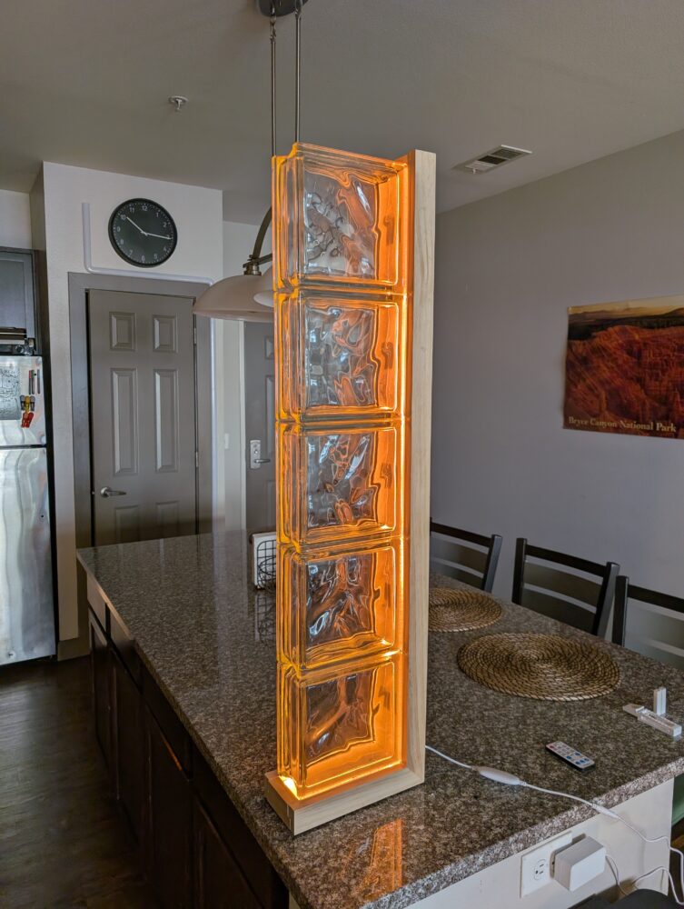
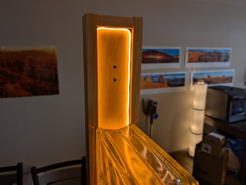
For my main project, I made a mid-century modern furniture inspired floor lamp. I used glass blocks and diffused LED strips as the primary lighting element, and the frame is manufactured using pine hardwood. The overall height of the lamp is ~3.5 feet tall, and is powered by a wall plug. The LED strip is a 2700k warm white diffused LED strip, that includes a controller and remote to adjust the brightness and lighting mode. This project was created as a statement piece for my living room, that fits the aesthetic of me and my own space.
Materials:
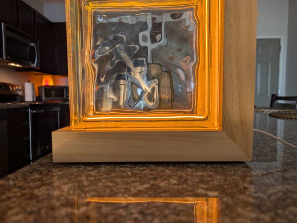
The first thing I purchased was the 5 glass blocks that I wanted. While I had a lot of options, I opted for the ‘wave’ style of block, due to both the cheaper price and organic look. For the LED strip, I ended up using one that I already had, since it already had a diffused material over it that mitigated the need for additional diffusion material. These LED strips are 3700k warm white, and included a remote to adjust mode/brightness, along with a built in controller on the cord. For the frame, I purchased pine hardwood boards from Home Depot. I went with pine due to its affordable price, ease of staining, and modern look, which contributes to my target aesthetic of mid century modern. To mount the blocks, I 3D printed some mounting pieces using ABS on my own 3D printer.
Building the Frame:
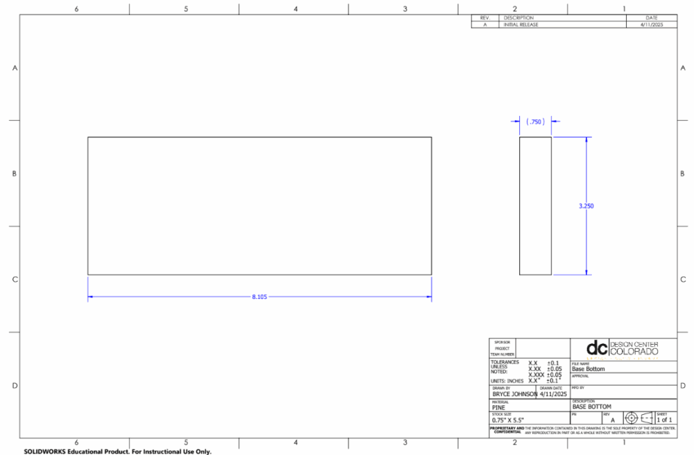
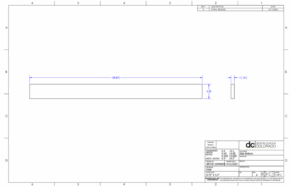
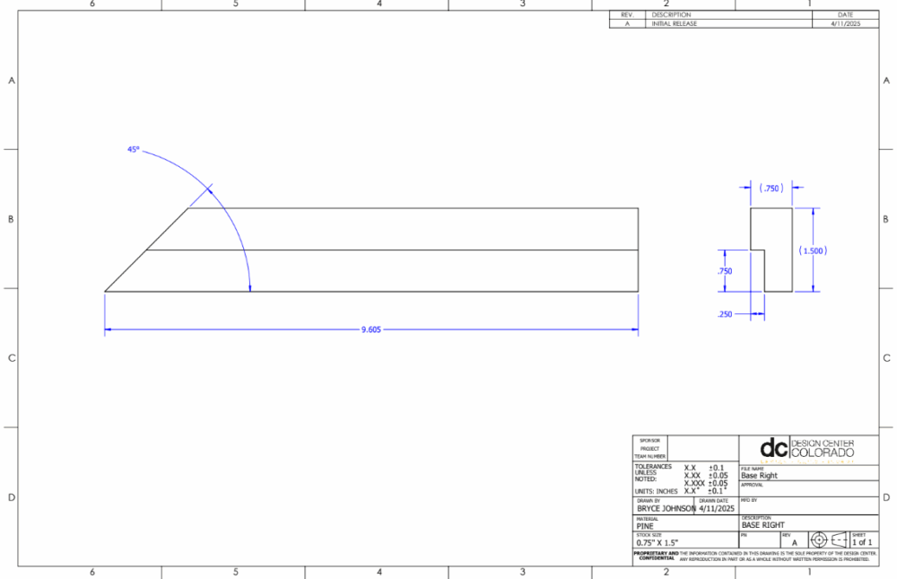
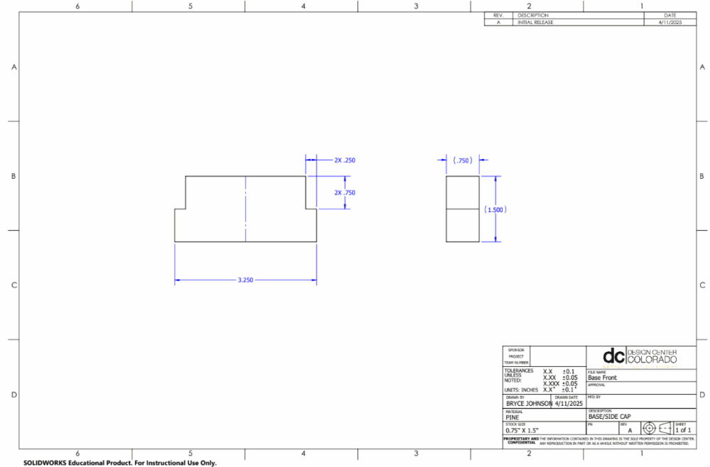
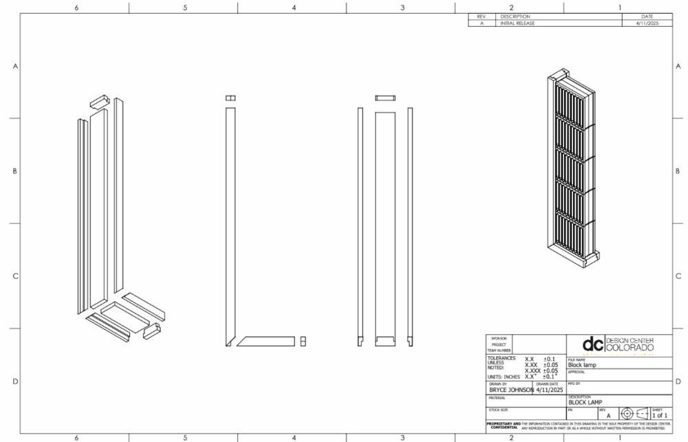
For the frame, I created drawings for each of the parts that I needed, so that I would be able to differentiate between the different boards. Many of the parts of the frame look very similar, so I made sure each of the parts had unique names that described their location. Since I created the parts in SolidWorks, I was able to quickly generate drawings for each of the components with relative ease, and I could be sure that everything would fit together nicely. As described above, I bought pine hardwood to make the components. The two stock pieces of board were 1.5”x.75”x8′ and 5.5”x.75”x8′. The dimensions of the boards are important, because I tried to make sure I could reduce the total number of cuts I would need to do by designing the frame around standard dimensioned boards. As an example, all of the outer framing pieces are 1.5”x.75”, meaning I would not need to make any additional cuts along the length of the board for 4 out of the 8 pieces.
I assembled the frame at the ITLL wood shop on CU campus. Thankfully, all of the tools I needed were there, including a miter saw, router, and a table saw. All of the boards needed some of these power tools to complete, especially since the assembly of my components relies on intersecting slots. I was able to complete all of the cuts and assembly of the frame in just a few hours, since I spent quite a bit of time designing the frame to be as simple as possible. This simplicity was both to save time during assembly, and because I had a lack of experience in woodworking, where I was aware that attempting a something more complex would likely become problematic.
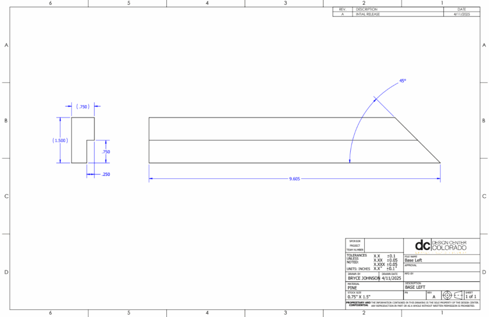
Base pieces: These parts were the easiest to make, as they did not involve any extra features. The thickness of the boards were already at .75”, all I needed to do was cut them to size. To make the cuts along the board, I used the table saw, where I made a singular cut of the entire length at once. To cut the boards to the correct length, I used the miter saw to cut the lengths I needed.
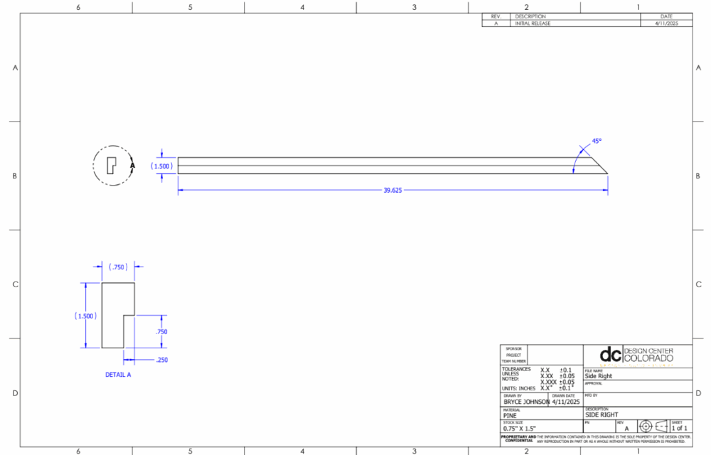
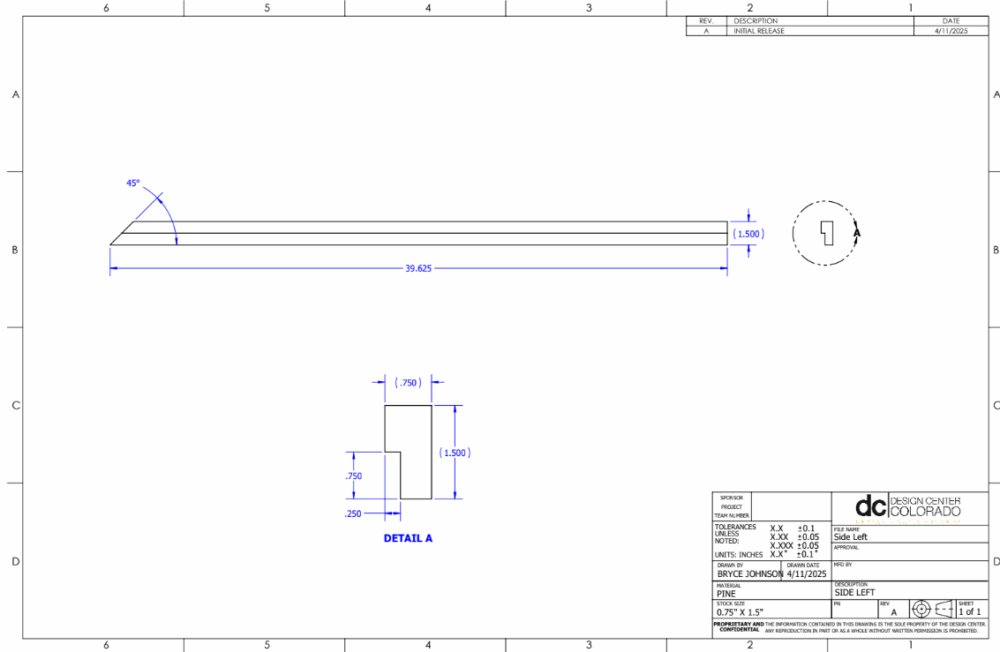
Side pieces: There are 4 total side pieces, each of which have very similar geometry. The cross sectional dimensions of these pieces are all the same, and all match the stock size of the board. Each of the boards have 3 features that needed to be cut: A slot along the length, a flat cut on one end, and a 45 degree cut on the other to create the miter joint. To create the slots, I used a routing table with a 3/4” long router bit, and slid all of the pieces along the table to create the cuts at just the right size. This allowed me to make the slot in a single cutting operation. To cut the ends at a 45 degree angle, I used a miter saw and rotated the mount along the base to 45 degrees to make my cuts. Here it was important to use the drawings to make sure I made each of these cuts on the correct side of the board. To make the flat end cuts, I just returned the miter saw to the neutral position.
End Caps: These pieces where the only duplicate wooden components on the assembly. To make them, I needed to cut out the corners of the blocks so that they could fit around the side pieces and align the ends of the assembly. To achieve this, I cut the pieces to length using a miter saw, then mounted them onto a milling machine. I found a 1” depth wood milling bit, and created the cuts by running the bit across the board in a single pass.
Assembly: My goal for the assembly of the frame was to not use any fasteners that could be exposed and show through the blocks or through the outside edges of the frame. Because each of the wood pieces fit together with slots, I was able to get everything together using only wood glue. I started by assembling the horizontal and vertical sections separately. I glued the base and side pieces together first, making sure to use a large amount of glue, then clamping tightly using multiple different clamps. Once clamped, I wiped away the excess wood glue that seeped out from in between the joints. Once the parts were comfortably together, which takes about 5 minutes per step, I then attached the end caps with a small amount of wood glue. Lastly, I needed to combine the horizontal and vertical sections of the frame, which i achieved by once again using wood glue and some 90 degree angled clamps. I allowed this section more time to dry, since it was the most structurally important.
Attaching the LEDS:
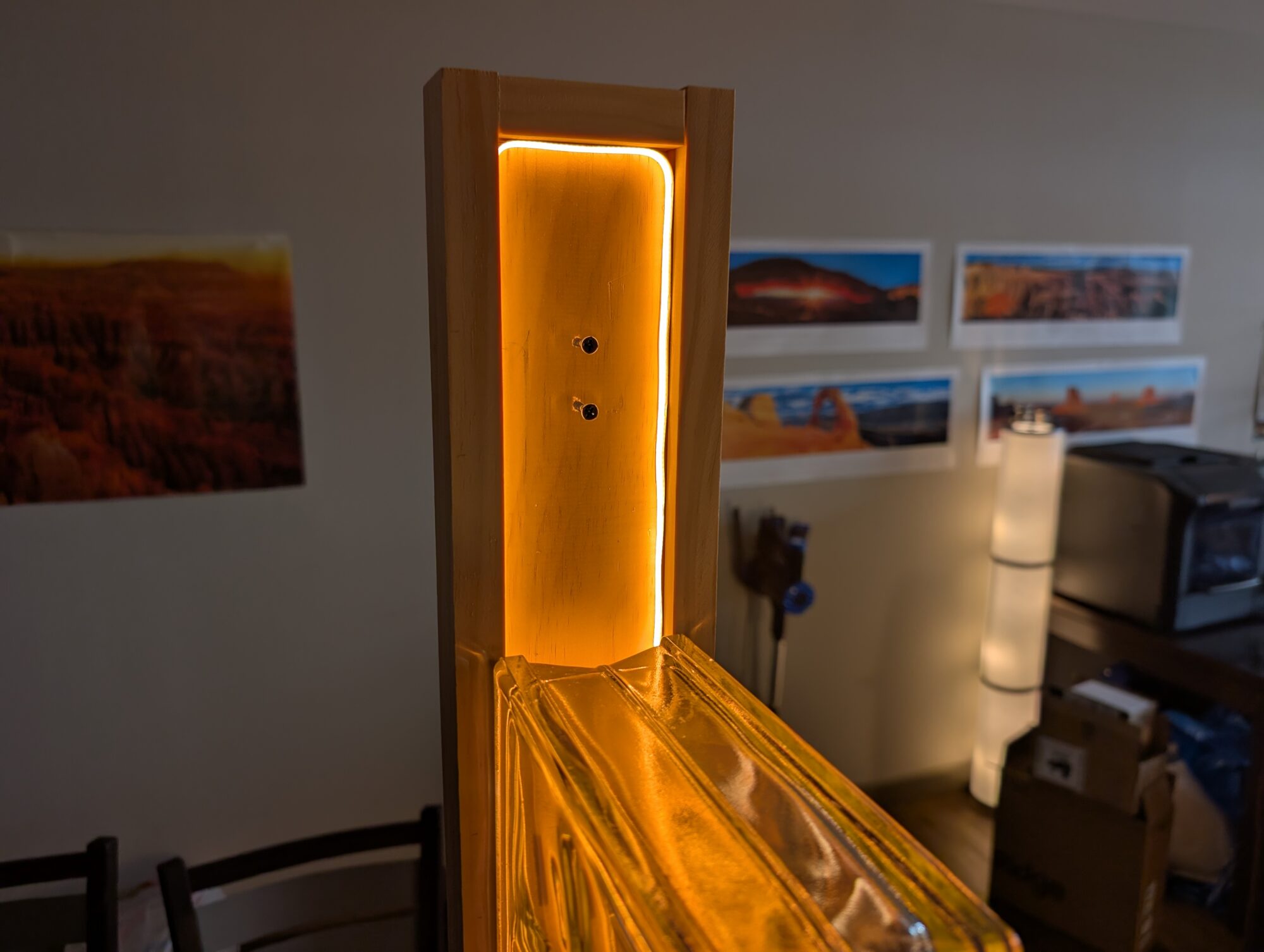
Attaching the LEDs ended up being the easiest component of the project. They were already adhesive backed, so I removed the covering and lined them around the inside surfaces of the frame created by the side pieces. So far, the adhesive material is proving to be strong enough and no part of the strip has come loose. To route the power and controller for the LED strip, I made sure that both ends of the strip terminated at the inside corner, so that routing the wire was as easy as possible. I then drilled a hole that was the size of the connecter though the backside of the frame. I press fit one end of the connecter into this hole, and ended up with a clean wiring solution.
Preparing/Attaching the Blocks:
When I received the glass blocks, I was unaware that they would have a coating on the outside of them that covers the light from escaping the sides of the blocks. This coating is here to prep the surface for attaching them with concrete, as that is the most common application when building with glass blocks. When I had bought the blocks, it was hard to tell whether or not this coating was here, so I needed to find a way to get it off of some of the surfaces.
Removing this material was quite difficult. I was not sure exactly what it was, so my first attempt was to use a heat gun and acetone to remove it from the sides that were not facing the LEDs. This proved to be ineffective, so I resorted to using a heat gun and paint scraper to slowly remove all the material. This was not fun, and involved several hours of just scraping to get everything off. Even after this, there was still some leftover material, but I removed enough to where it is not noticeable without close inspection.
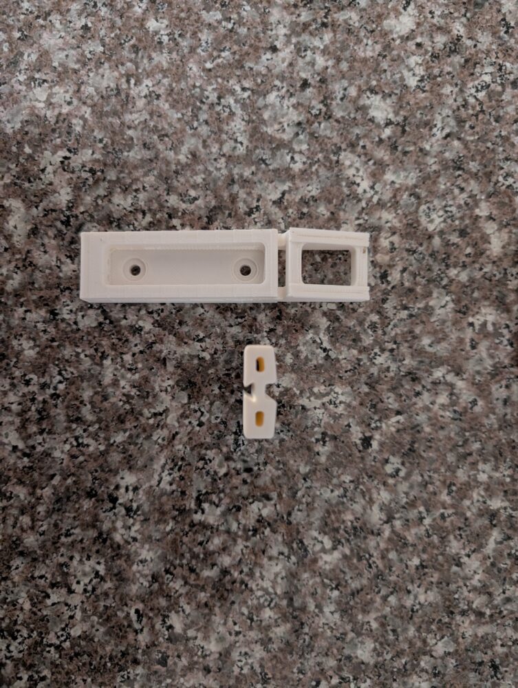
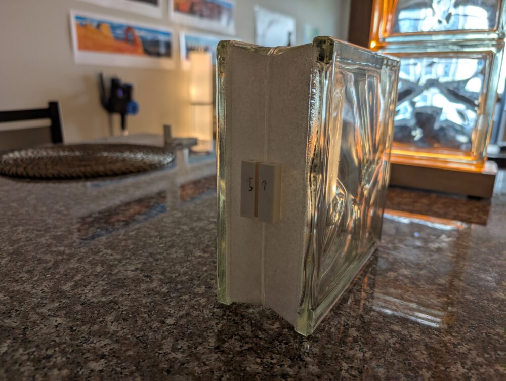
To attach the blocks, I tried a few methods. This proved to be a bit of a challenge, since the blocks had low tolerances and where not all exactly the same size, with mild angular and dimensional variation between them. Additionally, they were quite heavy, around 5 pounds per block, which meant that the mount could not actually support the weight of the blocks, they just needed to be kept from moving away from the frame. The solution that ended up working was a mount that attached to the blocks using some plastic glue, and attached to the frame using slots that fit over the heads of wood screws. This allowed me to attach wood screws to the frame, adjust their position by rotation, and then slide the blocks over them. This allowed adjustability between blocks with one mount, while isolating the load against the base of the frame.
Conclusion:
Once the wooden frame, glass blocks, and lighting are all combined, the project turns into a fully functional lamp that fills the mid-century modern aesthetic that I was hoping for. As I had described, the lighting can be adjusted, and reflects off and diffuses through the glass blocks in a really cool way. The wave pattern of the glass blocks makes the light look very organic, while the overall shape and style still feels very linear/angular.
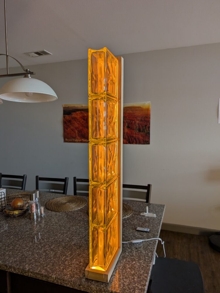
I am really happy with how the project turned out. I believe I have created a style of lamp that has not really been explored yet, and that has combined several design ideas that I like. I plan on keeping this lamp in my bedroom or living room as a statement piece for the foreseeable future, since it closely matches my own aesthetic that I maintain in my space.
3 Comments. Leave new
The soft orange 2700k light is a great choice. I think it matches the wood color well. It would be cool if the lights were rgb and let you change the color.
Bryce! Your lamp is astonishing! You really brought your vision to life. The diffuse glow works beautifully with the water glass block. Id love to see a stylized, borderline advertisement, photo to really underline the ambiance created by your creation. Cheers!
Looks so clean, and I love how the light refracts and illuminates in the glass. Can not wait to see it at expo. I believe in a bathroom setting would best highlight how great the lamp is.