
Project Timeline
This section documents the full journey from idea to final artifact. It outlines the actual design process through a week-by-week timeline, describes how the sculptures were modeled, fabricated, and assembled, and ends with a reflection comparing the original vision with the final outcome. While function played a role, the focus remained on aesthetics, illusion, and clean visual transitions.
Timeline & Progress Plan
| Date | Task | Details |
|---|---|---|
| March 15–20 | Finalize the design choice | Selected transformation pairs based on feasibility and impact. Chose Sad ↔ Smiley and Batman ↔ Superman for emotional and cultural contrast. |
| March 21–25 | Create detailed CAD model | Modeled dual-view extrusions using orthographic sketches and strategic lofts in SolidWorks. Focused on clarity and geometric harmony. |
| March 26–30 | Print small-scale test | Printed scaled prototypes to evaluate illusion strength and surface resolution. Adjusted thickness and edge sharpness after tests. |
| April 1–5 | Fabricate final sculpture | Printed full-size models in white PLA with support structures. Ensured smooth transitions and clean viewing angles. |
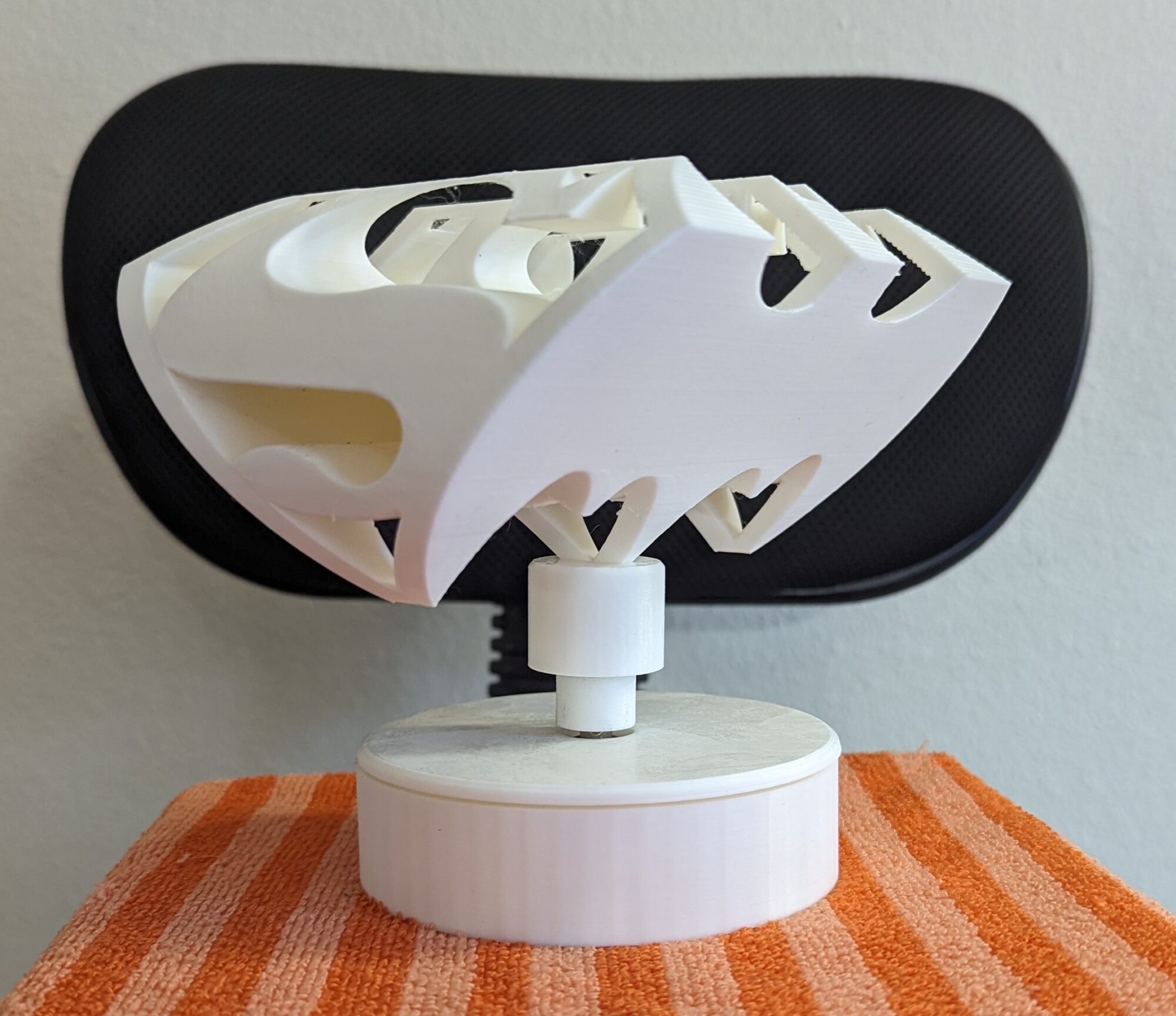
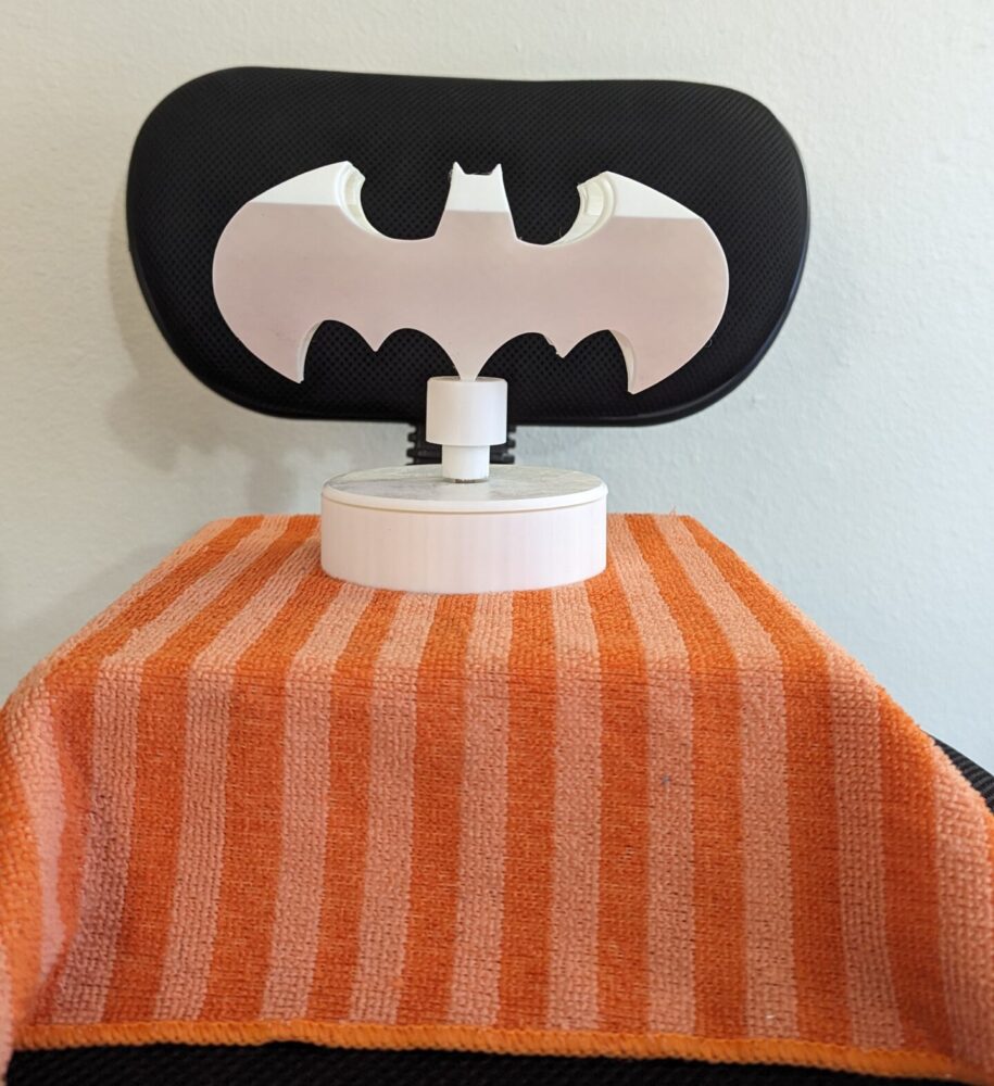
| April 6–10 | Assemble motor mechanism | Modeled a cylindrical motor base and a detachable mount. Designed a shaft pin permanently attached to the motor; each sculpture slots in. |
| April 11–14 | Test movement and refine | Verified balance, viewing stability, and slow rotation (1 RPM). Fine-tuned the fit and vertical alignment between pin and sculpture. |
| April 15–17 | Finishing touches | Applied light sanding only—no painting—to preserve a crisp, clean, minimalist look consistent with the aesthetic. |
| April 18–20 | Document final results | Took high-resolution photos from both viewing angles and mid-transition. Created presentation-ready shots and diagrams. |
| April 21–22 | Prepare final report & slides | Compiled fabrication log, aesthetic analysis, and documentation into final report and live presentation assets. |
Detailed Fabrication & Modeling Process
1. Base System Design
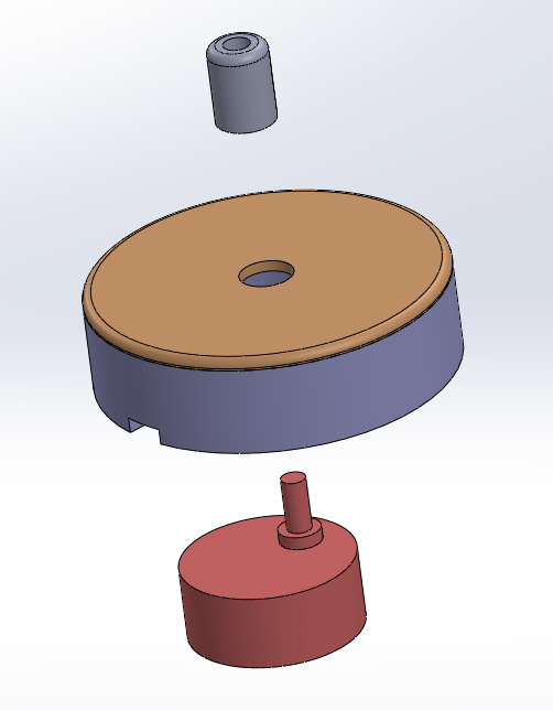
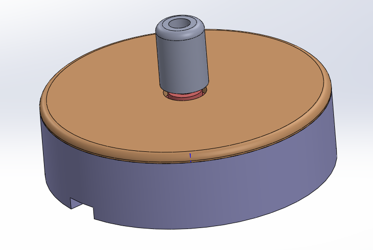
To ensure flexibility and ease of presentation, I first designed a universal motor base:
-
The motor shaft holds a permanently attached steel pin, which is the connection point for every sculpture.
-
Each sculpture has a custom insert that slides onto this pin, making switching between designs easy.
-
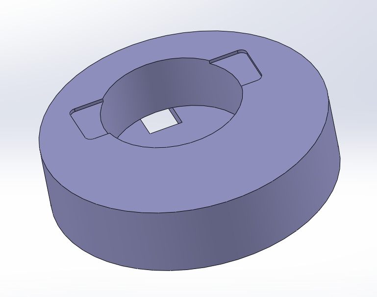
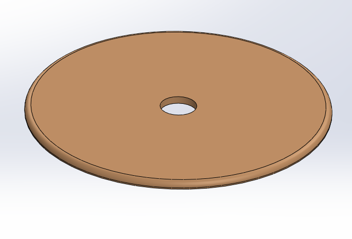
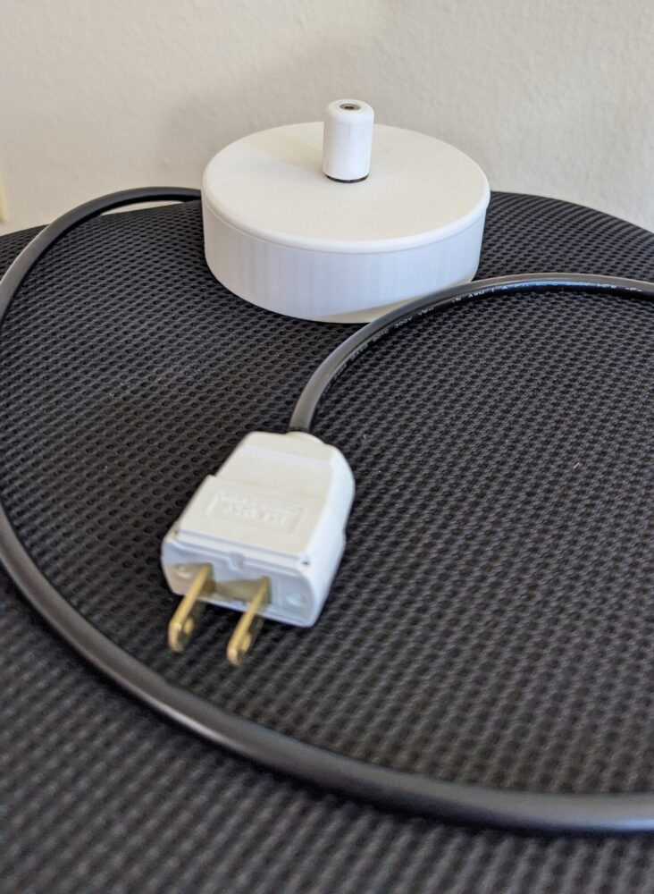
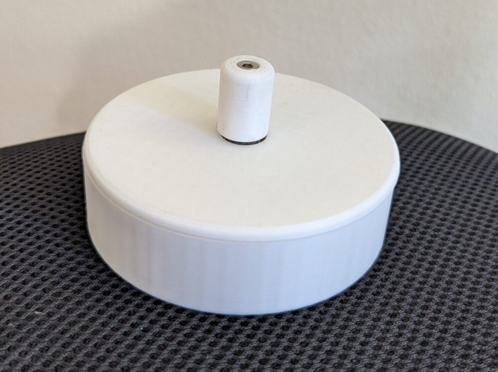
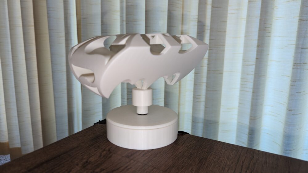
The motor is enclosed in a 3D-printed cylindrical housing with a separate cover that hides wiring and supports the sculpture.
This design allows for a modular display, where sculptures can be swapped without disassembling the mechanism.
2. Dual-Perspective CAD Modeling
Each sculpture was modeled in SolidWorks:
-
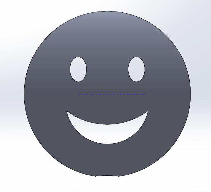
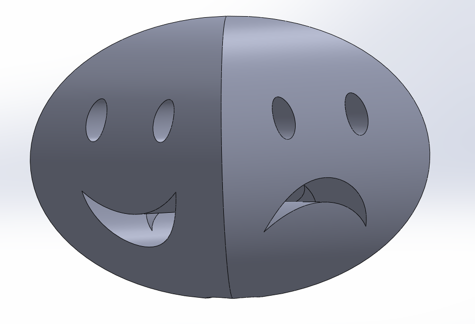
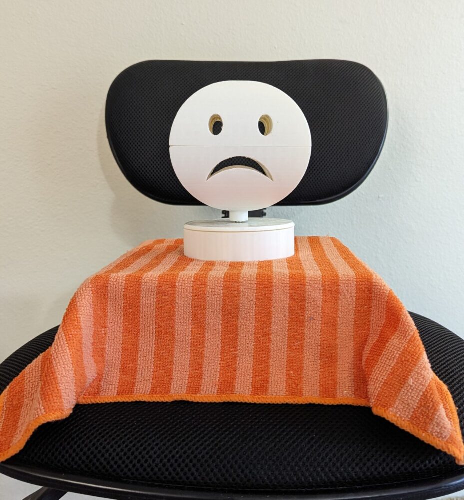
Imported two perpendicular silhouettes—e.g., sad and smiley face.
-
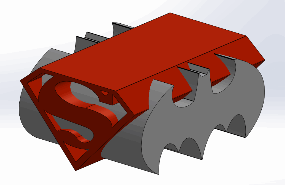
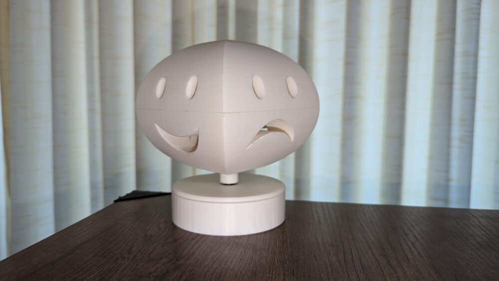
Created extrusion paths and used Lofted Boss/Base to morph one shape into the other across 90 degrees.
-
Used Boolean trimming and filleting to enhance form clarity.
-
Key challenge: maintaining recognizable forms while ensuring physical manufacturability (especially overhangs and bridge areas).

3. 3D Printing
-
Material: White PLA, chosen for visual neutrality and clean edge contrast.
-
Printer settings: 0.2 mm layer height, 15% infill, support enabled.
-
Minimal post-processing: slight sanding of edges to smooth out transitions but kept the raw material finish.
Two sculptures were printed:
-
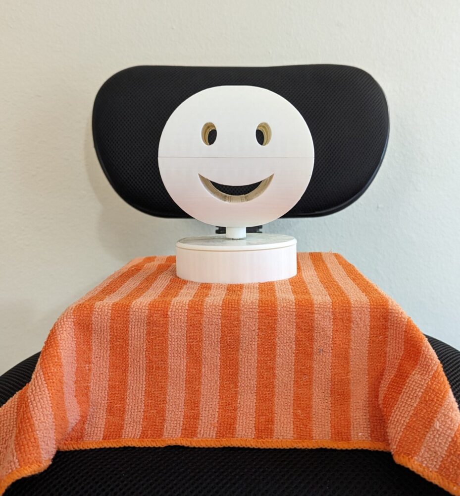
Sad ↔ Smiley Face (simplified emotional duality)
-
-
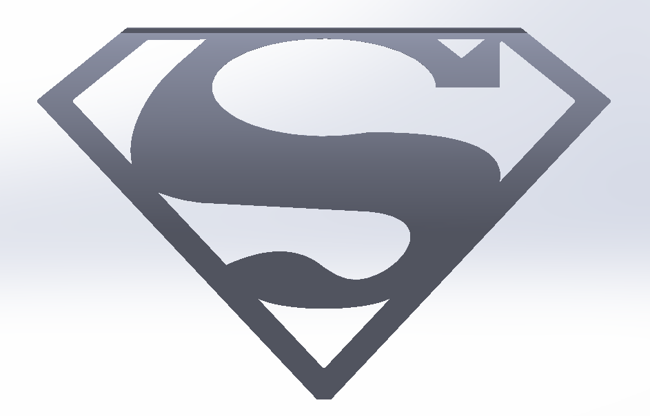
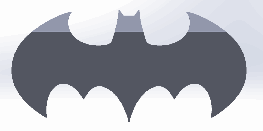
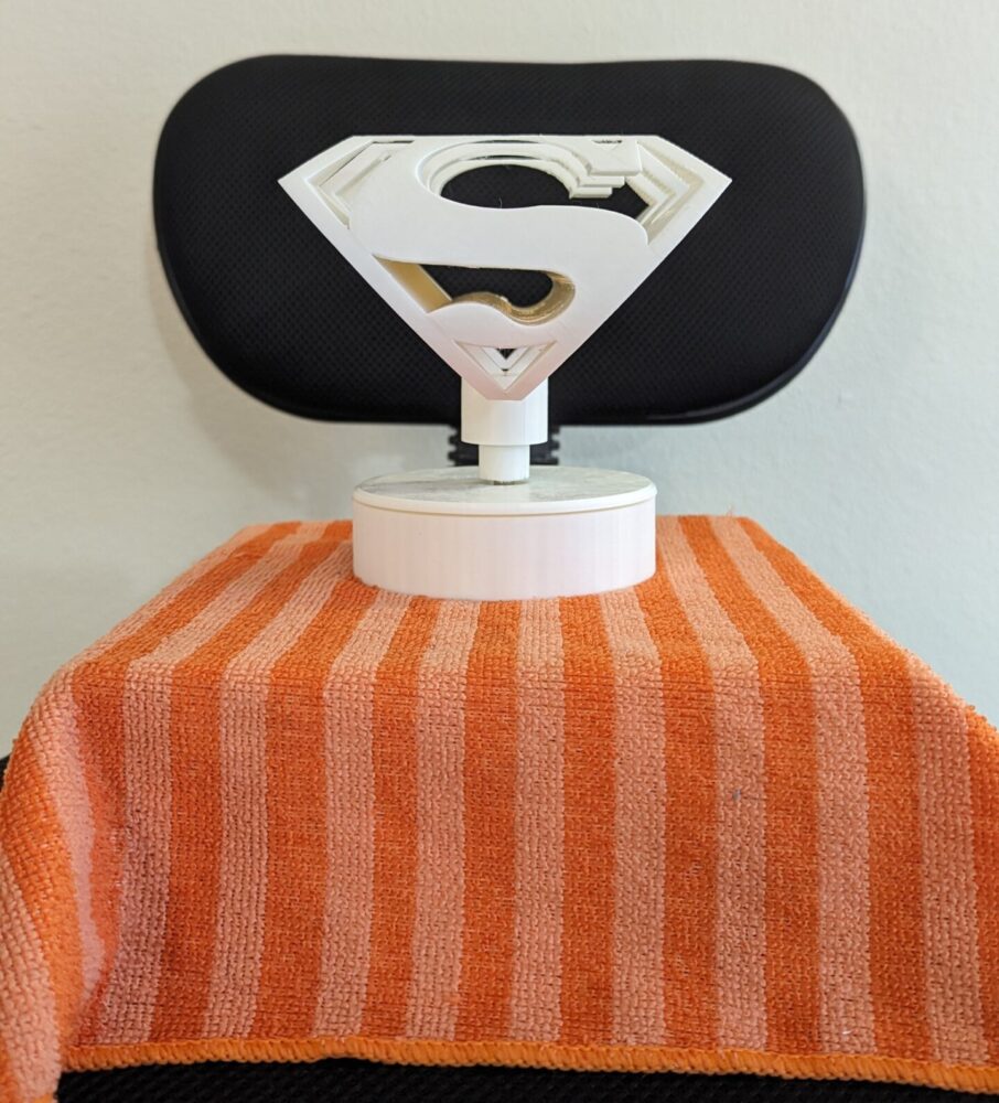
Batman ↔ Superman Logos (cultural identity flip)
4. Motor Integration
The DC gear motor (1 RPM) was mounted inside the 3D-printed base:
-
A metal pin was epoxied into the shaft and used as the universal connection point.
-
The sculpture was designed with an internal hole that fits tightly onto the pin—secure, but removable.
-
This setup creates a seamless continuous rotation, revealing the shift between the two perspectives.
5. Testing & Adjustment
After assembly:
-
The motion was tested to verify balance and legibility of both views at slow speeds.
-
No vibration or mechanical distortion was present.
-
I iteratively tweaked sculpture wall thickness and pin tolerances for a snug fit.
6. Documentation & Final Prep
-
Rotating display shots showing transition zones
-
Annotated renderings and exploded CAD diagram
Conclusion: Aesthetic Reflection & Lessons Learned
From Plan to Reality
Initially, I planned to make just one illusion piece. In the end, I created a rotating, modular platform and multiple dual-view sculptures. The final product exceeded my expectations both in visual strength and object presence.
The clean finish, crisp geometry, and slow, meditative rotation align beautifully with the aesthetic I envisioned:
“Clean Geometric Duality”—where form is both static and in flux, minimal yet complex.
What I Would Do Differently
-
Color Contrast: Though I kept to monochrome, a duotone (e.g., black + white) could have further enhanced legibility. Or a different color base making it separate from the sculpture itself.
-
Physical Prototyping Earlier: Quick foam-core mockups might’ve helped refine silhouette compatibility before CAD.
-
More Sculpture Pairs: Given how smooth the process became, I wish I had time to make 3–4 variations instead of just 2.
What Happens Next
-
The sculpture and motor base will be shown at our final studio showcase.
-
Long-term, I hope to expand this into a collection of dual-view objects—each one revealing something surprising, playful, or poetic.