
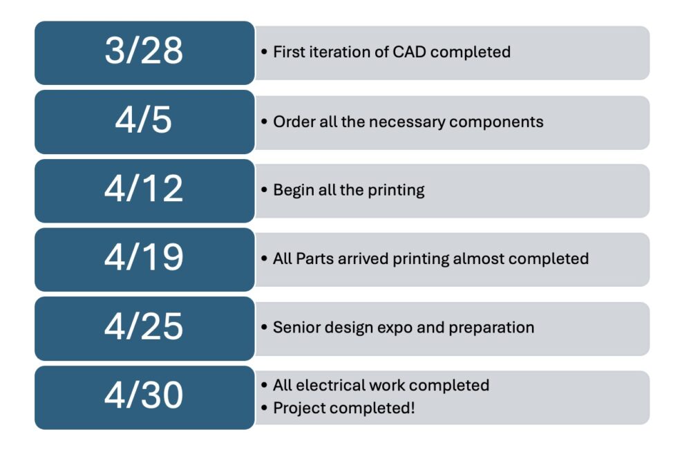
Here is the timeline for the project:
Exploration: I performed most of my exploration at the beginning of my project. As mentioned in my previous post, I was inspired to do this project by my friend Justin and my need for a watch winder. I have been looking consistently for a watch winder that would be helpful to me, and I always fell on the gyroscopic form. After searching different DIY tutorials, I finally found the one I wanted.
Skill Acquisition: One of the main skills I was improving was assembling 3D parts. The majority of my prints are one-piece prints. It was interesting that the creator of the CAD files incorporated fasteners. I had to remove the supports, but the force fit for the fasteners was incorporated well. I still had to utilize a couple of different fasteners, so there were no clearance issues. I also worked to acquire skills in electrical work. I am unfamiliar with electrical work and soldering different electrical connections, so the main skills I acquired in this project involve those.
Looping: I looped around a similar idea and design for the project. My initial design sketch, as shown above, is very similar to my final sketch. The only thing that changed about the design was some of the forms. I had to change from the initial design because I realized that it may not have been the most realistic thing to accomplish in my time.
Shopping: The shopping was pretty easy. I bought the Arduino Nanos from Amazon, which only cost about $13. I also purchased the motors, motor drivers, and AC-DC converter from Amazon. The YouTube video I followed was pretty descriptive about many of the products necessary for the build, so it was easy to source them all. I also bought the push button switch that I used from Amazon. All of the materials that I did not purchase, I was able to find in the ITLL and the IdeaForge. These are the fasteners, the materials necessary to solder, and many wires and heat shrink that I used during the electrical project. One hiccup I faced was that the Arduino did not come with a communication wire, so I had to use the wire I used to charge my TI-84 calculator.
Here are all the parts that I purchased pictured below:
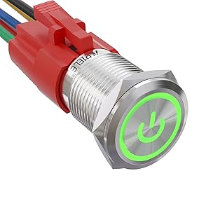
Figure 1: Push Button Switch Purchased from Amazon
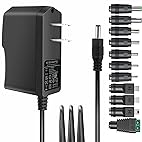
Figure 2: 5V DC plug Purchased from Amazon
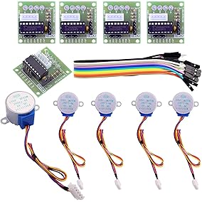
Figure 3: Stepper Motors and Drivers Purchased from Amazon
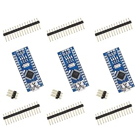
Figure 4: Arduino Nano Purchased from Amazon
The Arduino’s code is already programmed, so I must upload it to the actual Arduino. I made sure to read the code to understand how it works, but the ability to use the code that was provided for the project saved me a lot of time. I also followed the electrical schematic that is provided. The electrical work involved soldering and ensuring the connections were as shown in the schematic to ensure proper functionality.
Most of the artifacts were made and posted online at cults3d. So, I first downloaded all of these parts from the website. After that, I converted all the files from the download package to solid parts in SolidWorks. After I had all the parts in SolidWorks, I started experimenting with making them more unique. After trying this for a while, I realized that I could not edit the parts well because of how they were imported. I ended up just fileting some of the edges for the middle ring of the gyroscopic movement.
After printing all the parts, I began to complete the assembly. The process for this was pretty interesting. The assembly included a lot of small slots for M3 nuts. So, I press-fit all of the nuts into the complete assembly first. After that, I began to line up the parts and screw them all together. I started by screwing the motor to the top plate of the base. After that, I continued by putting all of the rings together and then screwing it to the top of the base.
After assembling the whole project, I moved on to the electrical work. I followed the diagram above. The soldering was the most challenging part of this process. I have little experience soldering things to a small board like the Arduino Nano. As shown above, I soldered the wires from the push button to make a common ground. Then, I soldered the rest of the push button connections to the Arduino. I connected the Arduino and stepper motor driver with jumper cables with pin connections. I first cut the male side of the jumpers. Then, I stripped the wire. After that, I soldered those to the D8-D11 positions. Finally, I just got some wire and soldered it to the power and Ground connections. After all that was done, I put the push button into the base and worked with the wiring to ensure it all fit in the base.
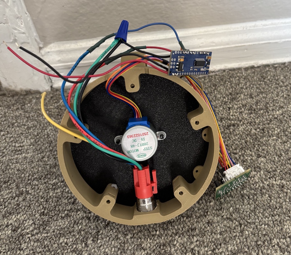
Figure 5: Internal Electronics of Watch Winder
Once everything was wired, I began troubleshooting the code for the Arduino. The code that was provided with the YouTube video did not work initially. So, I began to mess with the code. First, I troubleshooted the push button switch’s LED functionality. Then, I troubleshooted with the operation of the stepper motor. Then, I ensured the stepper motor did not turn unless the push button was pressed. Finally, I uploaded all of the code and then moved on.
The final step was screwing the bottom of the base on and then screwing the wires for power to the screw terminal that I got that works in combination with the AC-DC 5 V power supply.
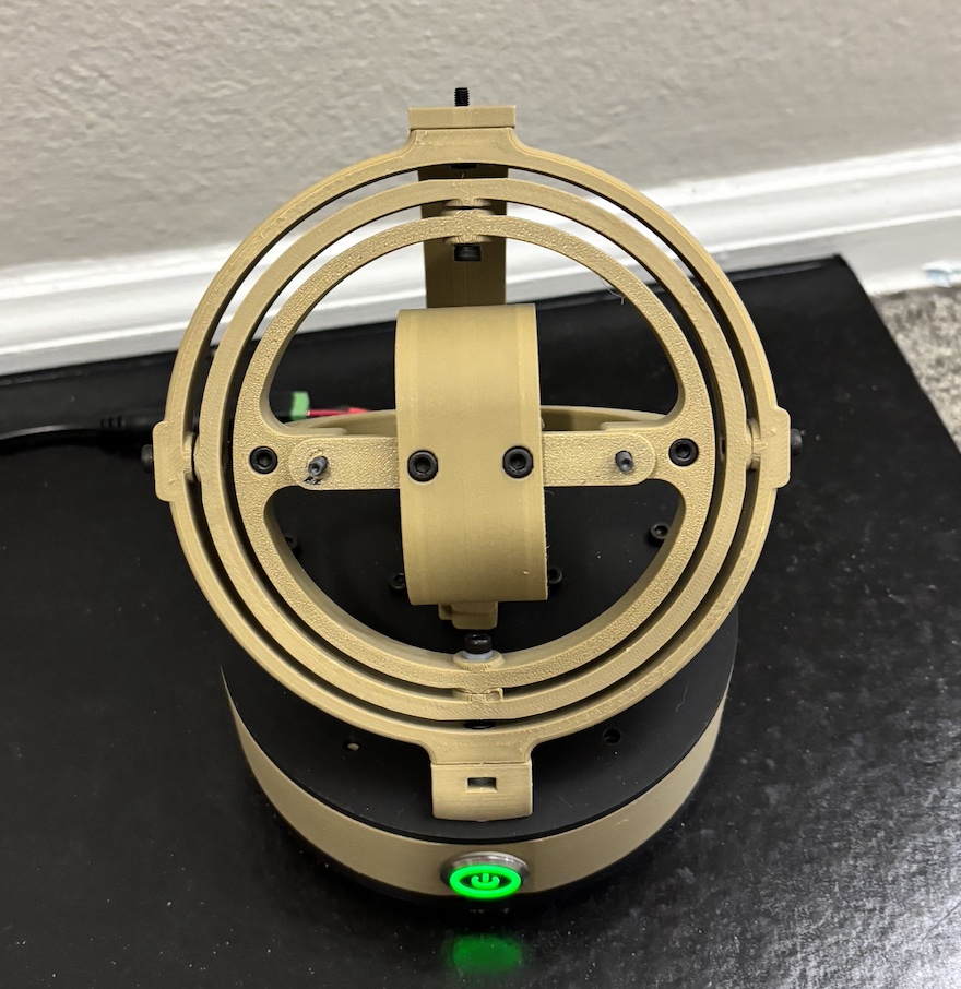
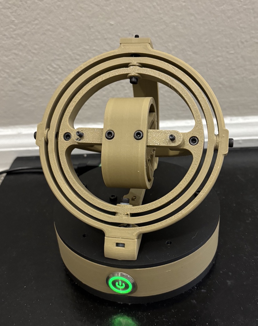
Figure 6: The Final Watch Winder
The start and the end of the plans were similar. I wish I had spent more time making the project more personalized. While I did change the colors and a little bit of the shape, I wish I could design it completely myself so I would be a bit more unique. It was hard because I had no time to ensure the piece was completely new.
Overall, I think that I met the aesthetic goals well. The vibe is mid-century modern, in my opinion: the circular curves and wood-like color help to follow the aesthetic. I think that if I can make it with even more unique shapes and vary how the base looks, I would be able to increase the aesthetic appeal. I am moving into a new apartment soon, so I want to keep up with the modern mid-century aesthetic.
I also wish that I had been able to make it out of different materials. If I were to make it out of wood, I believe it would have been much cooler. It also would have been sturdier. While the 3D printing allowed me to finish it quickly, there were compromises with the quality.
I also wish that I had a more powerful motor. The motor that I have moves rather slowly. Because of this, I am unsure if it is winding the watch very effectively. If I had a quicker and more powerful motor, I could wind the watch very quickly and charge it up more.
My creation will be displayed on my nightstand and used to wind my automatic watch. It is a very cool display piece that looks awesome while rotating. For future work, I plan on making more watch winders and giving them to my family as gifts. I have the materials to make about three more of them. Hopefully, I can customize them to make them more unique and look better.
References:
Project Inspo: https://www.youtube.com/watch?v=9xmiwsT9VRI
3D-Files: https://cults3d.com/en/3d-model/fashion/gyro-winder-watch-winder-remontoir-montre?srsltid=AfmBOorMWaezYh3AMaR7ixzpe82b-rDkKLTsjXLt6l3GPKj4u9BSh_dh