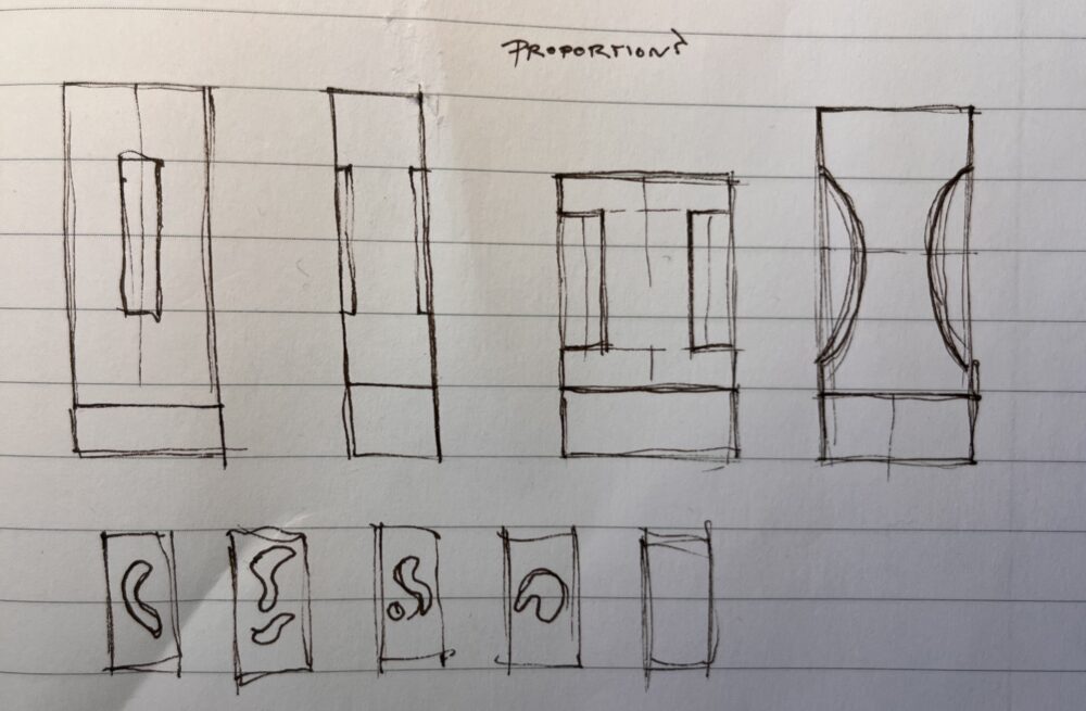
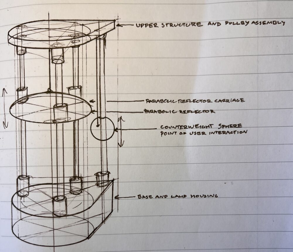
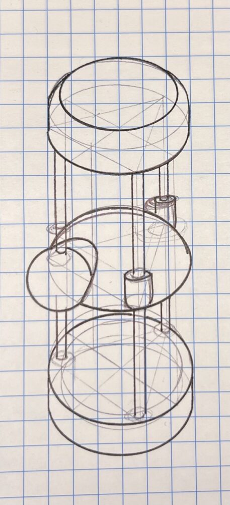
I began this project by sketching out some ideas on what I wanted the lamp to look like as well as its scale and functionality.
I chose to create a lamp for this project. I have always found beauty in simple shapes. My first project was in the space age aesthetic, a spherical lamp with a quasi-tetrahedral base. For this project, I wanted to experiment with light in a different way while conforming to the same general aesthetic.
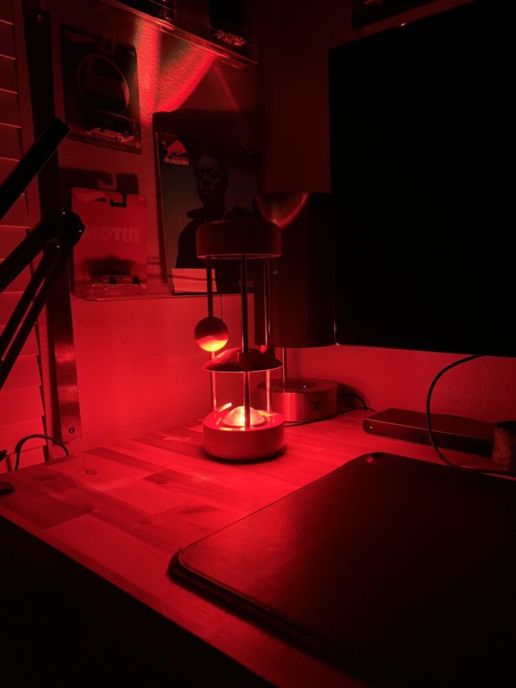
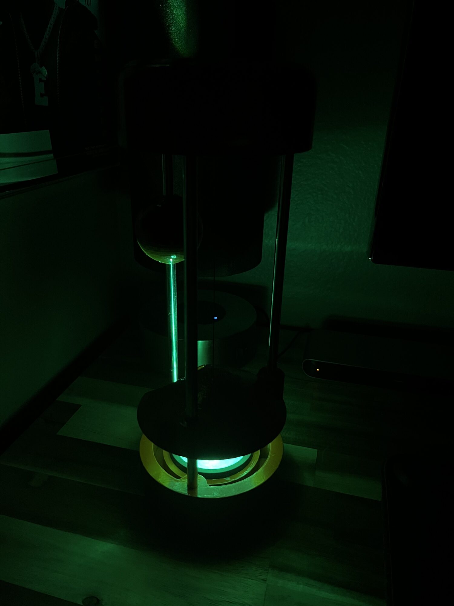
For my light source, I originally wanted to go with a traditional incandescent bulb, as it better fits the time period of my chosen aesthetics. Instead, I chose to repurpose an old sunset lamp as it offers more versatility without looking too modern.. This lamp provides a soft glow as well as an elliptical projection that stretches as the angle gets more oblique.
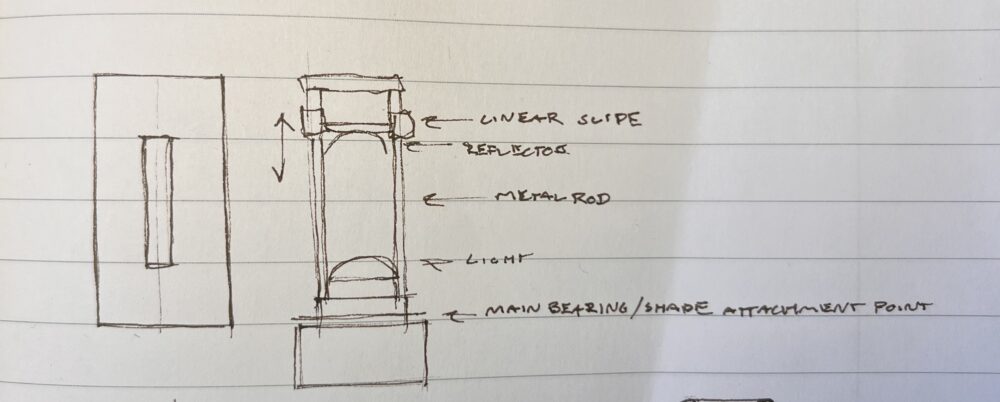
After the opposite aesthetic assignment, I evaluated the use of metal rods as my main structural element. I realized that this material, inspired by the industrial style, could work well with the aesthetics established previously. I had some 8mm rods leftover from another project that would work perfectly. This led me down another path; I also had 8mm linear slide bearings on hand so I decided to incorporate another dynamic element to manipulate the light. In essence, this would be a carriage that would slide up and down the rods that would serve as a reflector.
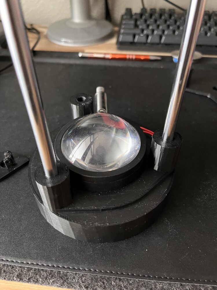
After sketching, I took measurements of prefab components and made a basic plan for layout and tolerances. I then designed the base, upper section and reflector of version one in CAD and used a 3D printer to create these pieces. After printing, I placed the rods into the base and upper section to get an idea of the scale of the lamp in real life.
![]()
This version proved the concept of using the rods as the main structural element. I originally thought that I would have to place a concrete puck in the base in order to increase stability, but the lamp was stable enough without it. I inserted the linear bearings into the reflector carriage to test out its stability and operation.
I was able to use learnings from version one to inform the design of version 2. Initially, I wanted to use a tactile knob as a friction set screw to maintain the position of the carriage. This however, would be cumbersome to use and would be unsightly. To keep the lamp as analog as possible, I decided to use a counterweight to keep the carriage in position.
Other physical adjustments include the ratio of rod diameter to base diameter, height of supports and general tolerance increases for support pieces.
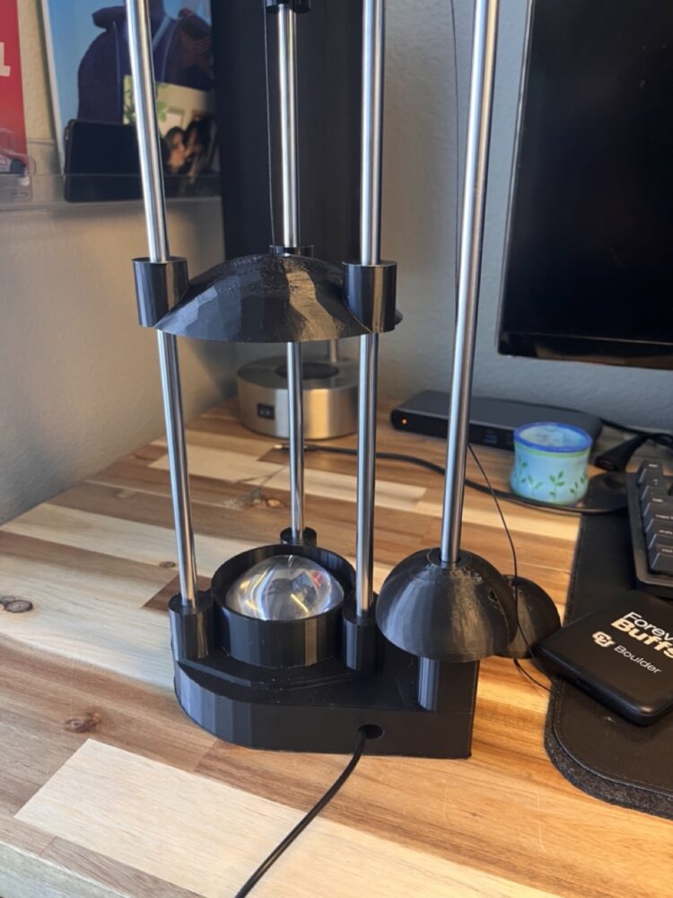
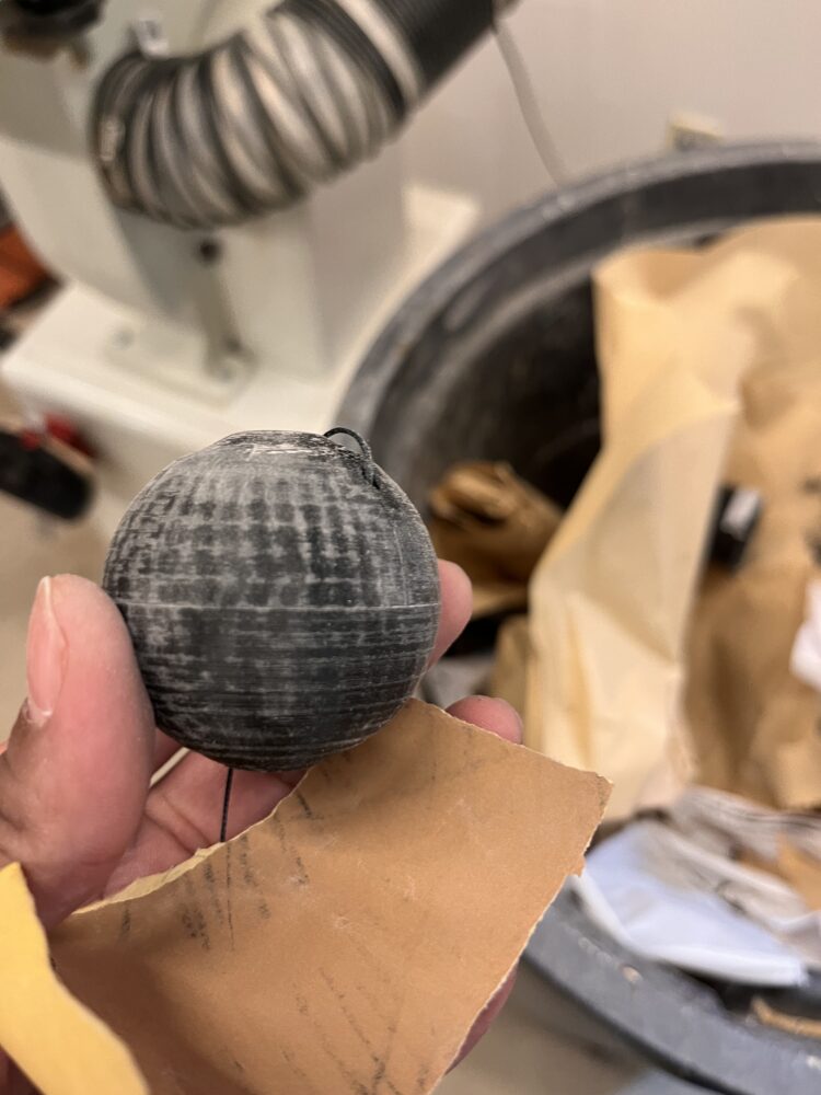
I went back to the drawing board and came up with another version, one with four support rods. The main three remained in the same configuration, and the fourth was added in the rear of the base. The new rod was for a counterweight, which would provide a way to manipulate the position of the reflector carriage and preserve the position of the carriage after movement. I made this counterweight a sphere, resembling a planet. I designed a pulley system to connect the counterweight and carriage, and willingly sacrificed mechanical simplicity in order to keep the outside of the lamp streamlined.
I then returned to CAD and designed these new pieces and incorporated the pulley mounts into the lower surface of the upper structure. I then printed these pieces out, and assembled the rods into the base and upper, and inserted the linear bearings into the reflector carriage and counterweight sphere.
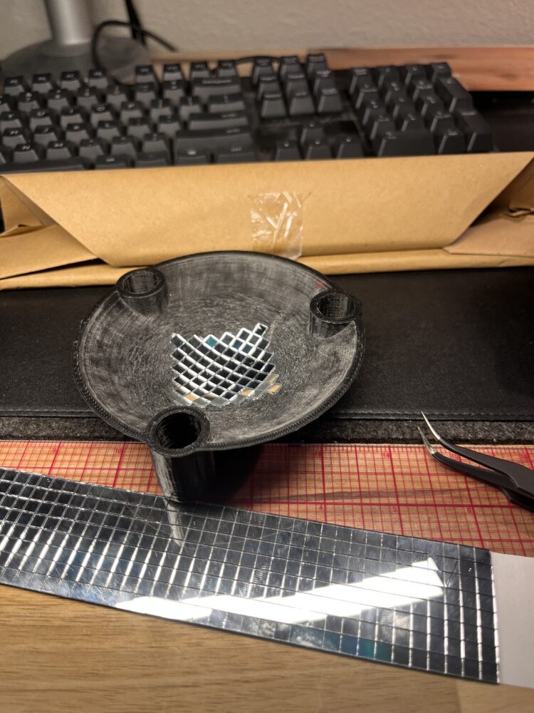
I chose to use disco glass mirror tiles, and adhered them individually to the underside of the reflector. This process was tedious and left my fingertips with many micro cuts. Injuries aside, this process was very therapeutic and went by quickly once I settled into a rhythm.
After assembling this version, I tested its function. The light diffused and reflected off of the mirror tiles nicely. However, I was not satisfied with the appearance of the lamp. It looked more like a gadget or a tool than a decorative lamp. This leaned too heavily towards the industrial style, and highlighted my least favorite parts about functional minimalism.
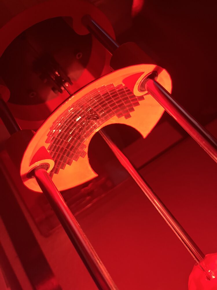
I then went back to the drawing board to see if I could figure out a solution that did not require an additional support rod. This would allow the lamp to return to a cylindrical footprint without adding too much visual clutter. The main design challenge was allowing the spherical counterweight to pass through the reflector carriage. I solved this by creating a cutout in the reflector. Although this would take away from the rotational symmetry of the reflector carriage and create a gap in the mirror tile reflections, this solution is overall more aesthetically appealing. The reflector carriage would slide along the front two rods, and the counterweight would slide along the rear rod.
 I then redesigned the base and upper section. For the base, I wanted to incorporate subtle design details without adding complexity. I started by removing the extrusions around the base of each rod and incorporating the support into the base.
After settling on the proportions of the base and upper and making some adjustments to tolerances, I made the updated pieces in CAD. I created a few renderings to see what different colors would look like.
 I was inspired by the muted pastels of mid century modern as well as the bright, radiant tones of the space age and googie styles. Using one of these colors would allow the lamp to be an interesting decorative piece when not in use.
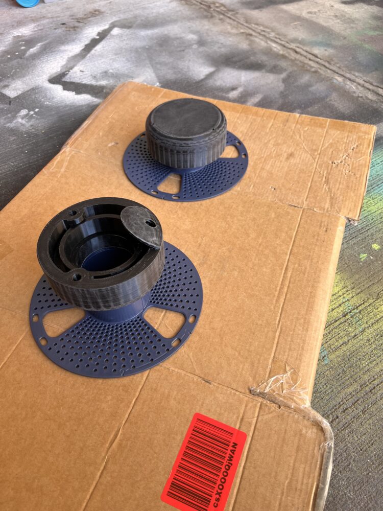
I then printed out the new components, and assembled them together.
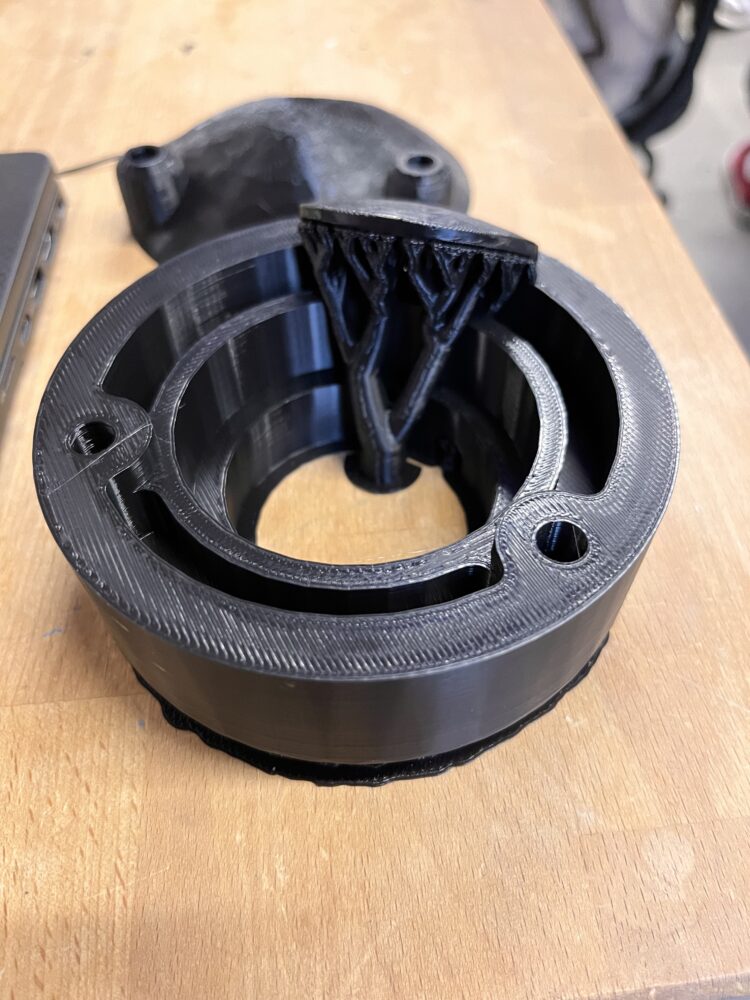
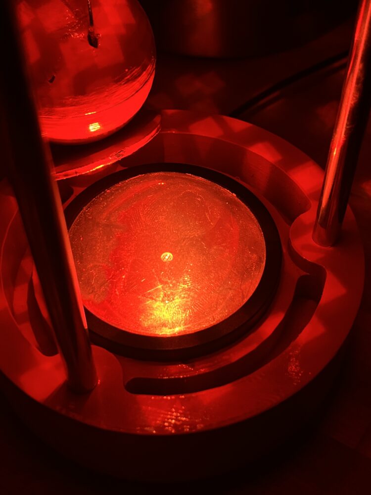
I adhered the disco mirror tiles to the underside of the reflector. Due to the cutout, making this pattern was more complicated. I did not want the reflected light to look too uneven, and I did not want the tiles to be visible when examined from the side.
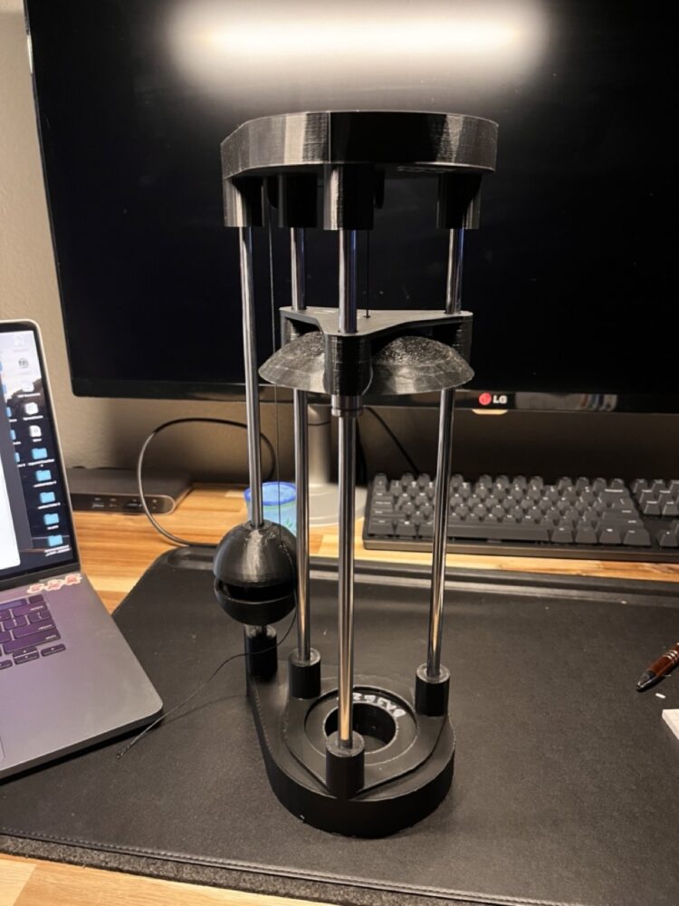
After gluing the tiles, I set up the pulley system and attached the reflector to the counterweight. Below are some pictures of this version.
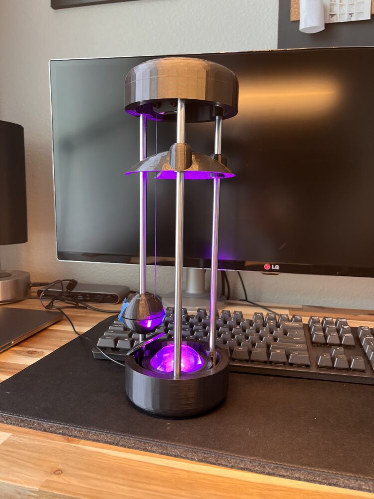
I was overall happy with the shape and silhouette of the lamp at this point. The lamp embodied my original design specifications better than the version before it.
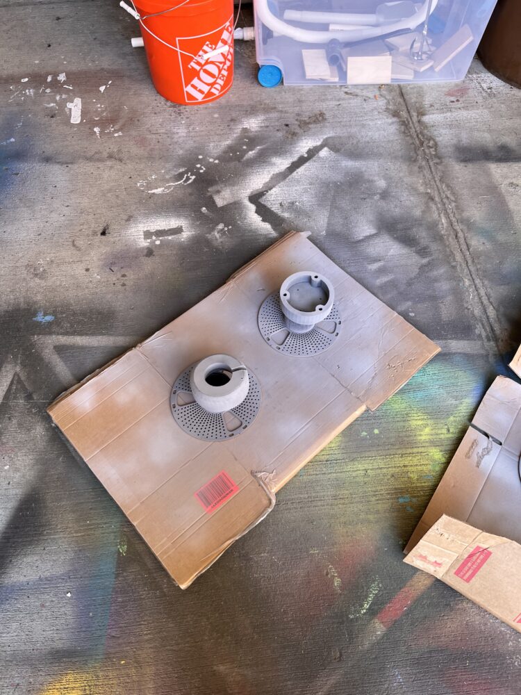
Once I had settled on the design of the pieces, I created a plan to prep and paint. Ideally, I would create the outer casing of the top and bottom structure out of injection molded plastic. Although FDM 3d printers are good for prototyping, the final product has many visible seams, layer lines and imperfections. I decided to do as much sanding and priming as I had time for, which wasn’t much.
I started with 150 grit sandpaper to remove bigger seam lines and remnants from support pieces. I then moved to 220 grit and finished with 400. This took out most of the imperfections, but there were still low spots. To combat this, I used automotive filler primer which sprays on like regular primer but builds like filler. I sprayed the pieces, let them dry, and then wet sanded.
Ideally, there would be at least three or four rounds of priming and wet sanding to incrementally finish the surface. After the first round, I realized that I did not have much time so I cut some corners. Instead of wet sanding between each primer coat, I just let it dry before spraying another coat.
At this point, the finish was looking nice so I let the components cure overnight. The next morning, I began to spray the gloss orange coat. Immediately, the bright orange began to reveal many of the blemishes I had tried to erase. To top it off, the last lacquer coat did not dry properly and began to stick to everything, resulting in some chips and bare spots. In hindsight, I should have spent more time preparing before starting to paint.
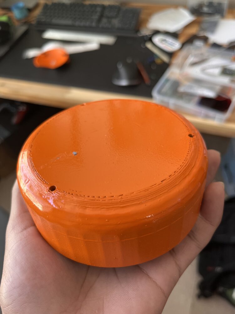
Luckily the parts look pretty good through a low resolution camera or if you squint your eyes. After the parts dried, I assembled everything together.
Physically fabricating this lamp was a fun and rewarding process. Much of this fabrication was aided by 3D printing, which allowed me to iterate through many different ideas and versions. My design process involves a lot of physical experimentation and I need to be able to see and feel the physical embodiment of a design in order to make sense of it. In addition to the three main iterations of the lamp, I went through many revisions and iterations of individual components. Hopefully I’ll be able to upcycle these some day.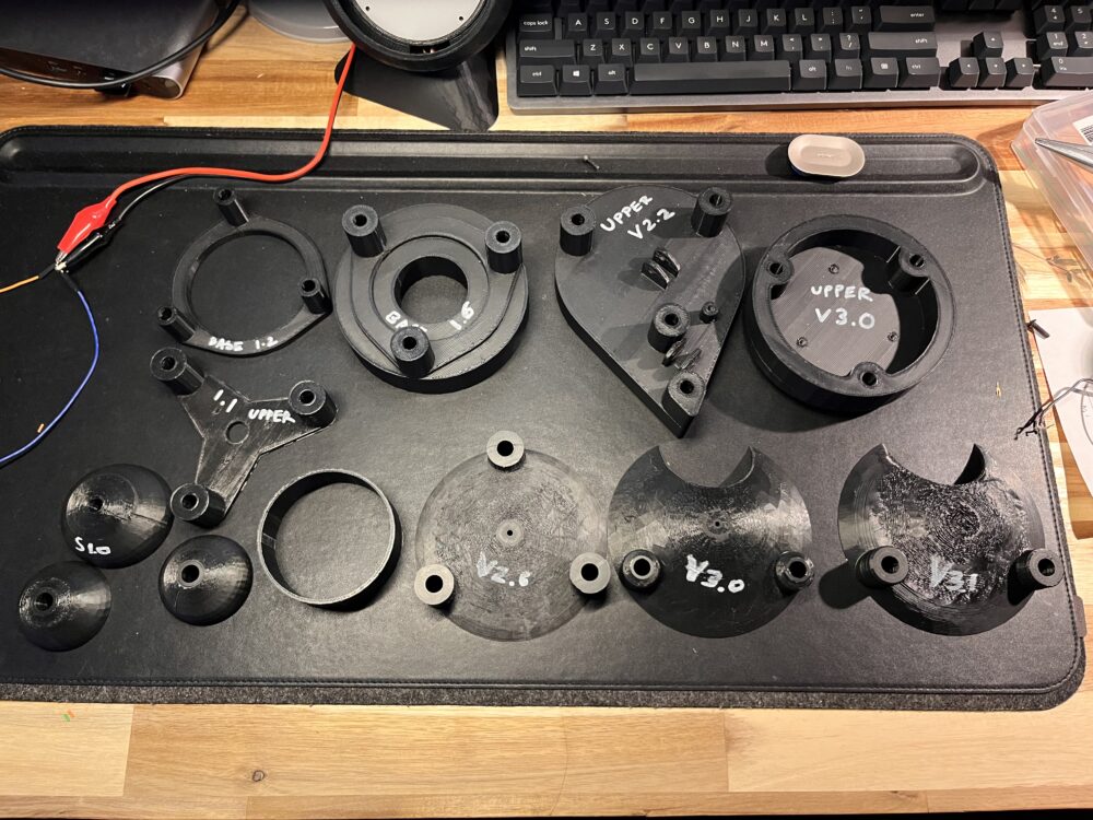
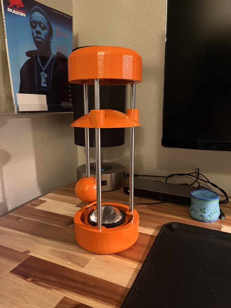
Finally, here are some pictures of the final version.