
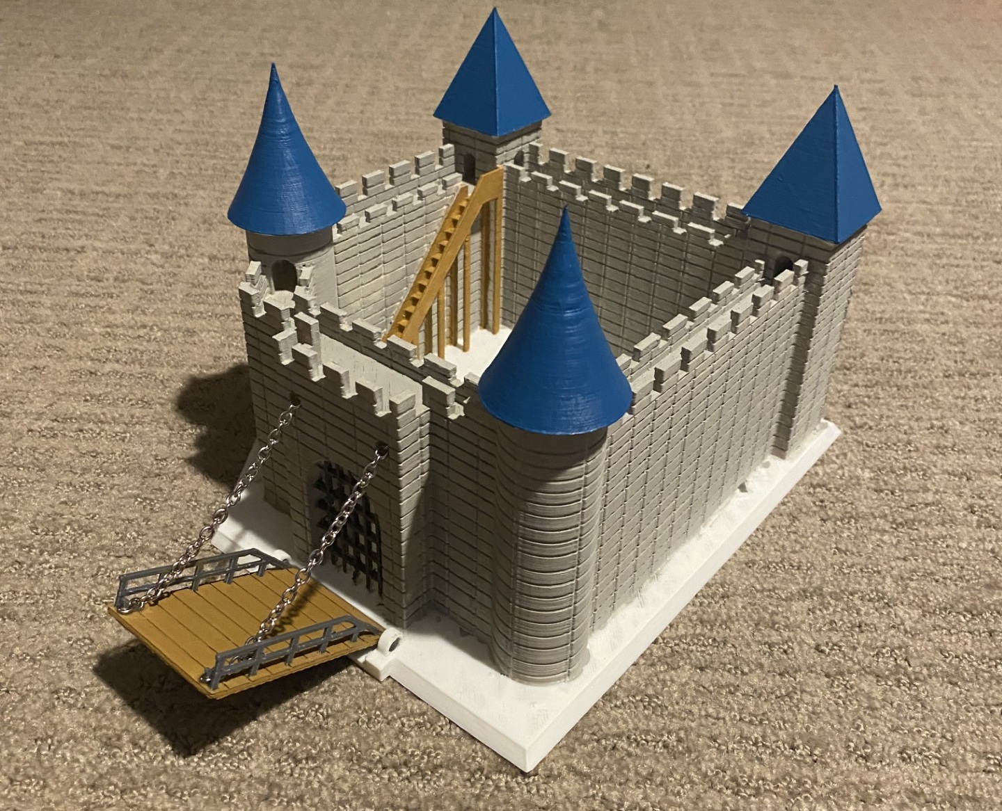
Part 1 of my final report went over some of the inspirations I took, specifications I created, aesthetics I wanted to achieve, and displayed the final product. This post will be going more in depth on how I actually created the artifact, what steps were involved, design challenges that arose, and where I want to go with it in the future. First, below is a timeline graphic I created to show how I spent my time on this project in a broad sense, over the about a month and a half time frame from when I decided on my direction.
Timeline
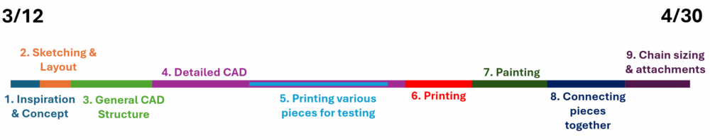
I color coded each step, and designated a length for each colored segment to correspond to about how long I spent on that piece compared to the others.
- The first step in the project was understanding what I wanted to create, which was a relatively quick process. I think we can all envision a medieval fortress, so this step mostly involved finding certain illustrations and real life castles to base some features off of (which I discussed in previous posts), understanding actual drawbridge functions, and that kind of thing.
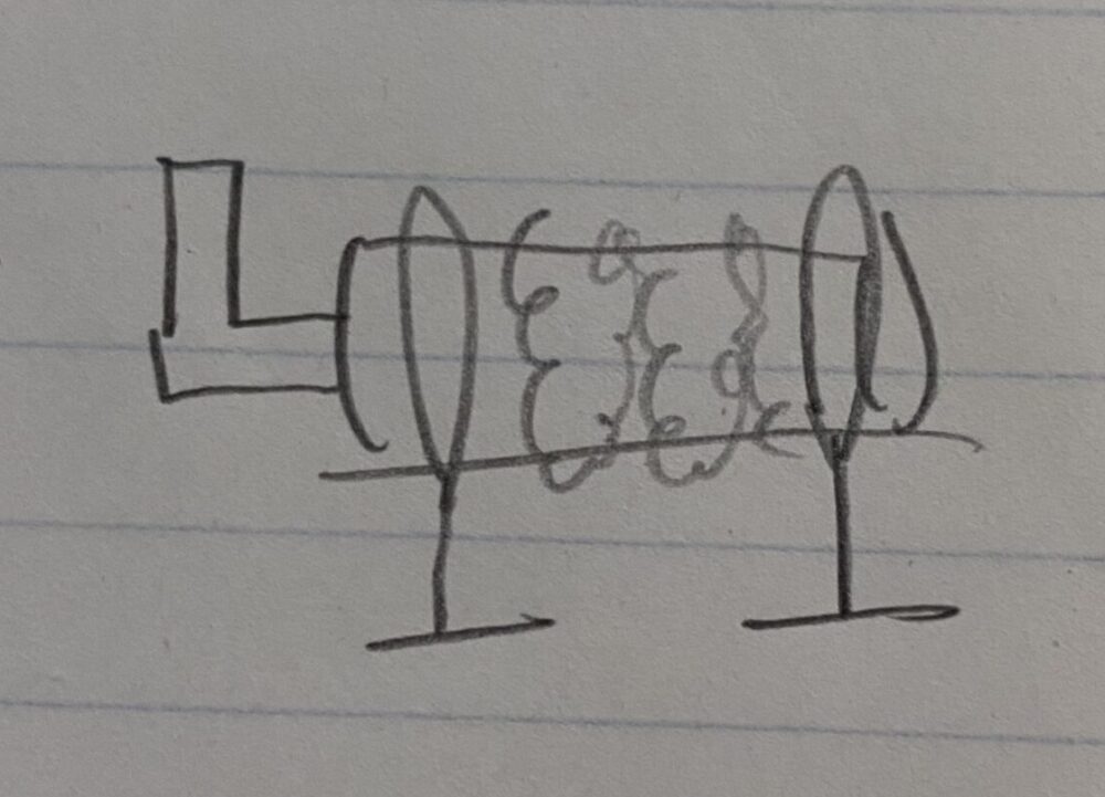
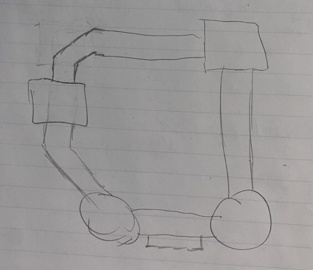
- Next was just laying out my overall design on paper before jumping straight into CAD. These were very basic sketches (as you can see, I’m not much of a drawer) which portrayed my ideas of how the crank would look/operate, and how the outer wall layout would look (this changed from what was sketched).
![]()
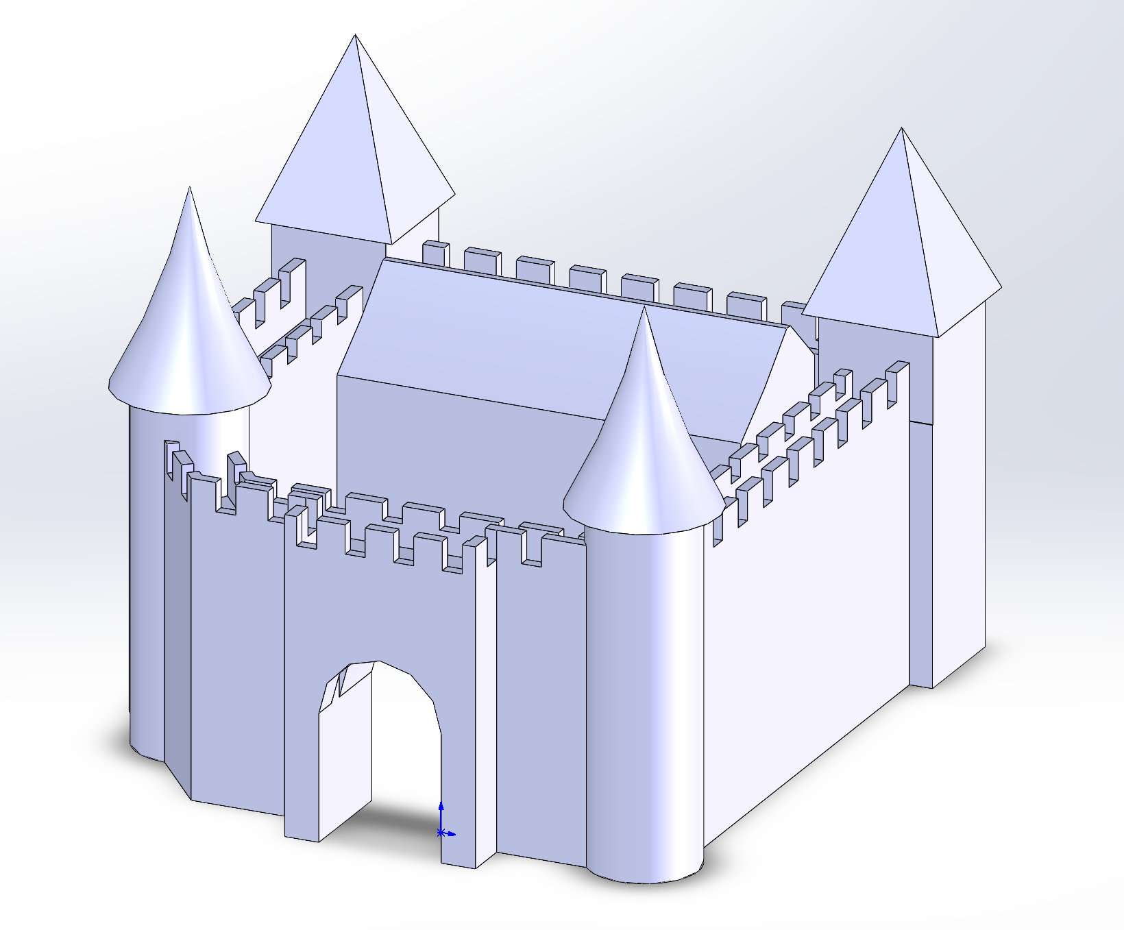
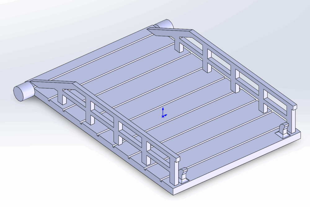
3. Next was translating these ideas and sketches to CAD, which is where the final product would live and be iterated on up until printing. I had some grand ideas in my mind about the final product, various different structures that could live inside the walls, but the most important and foundational piece were the walls themselves. I took a few iterations to get to what layout I wanted, like how it changed from the sketch. You can see in the screenshot below how there is a block in the center of the walls when I was trying to implement an actual livable castle part, but I just couldn’t make it work to my satisfaction with the already created walls in a timely manner, so I decided to just focus on the rest and I removed that block.
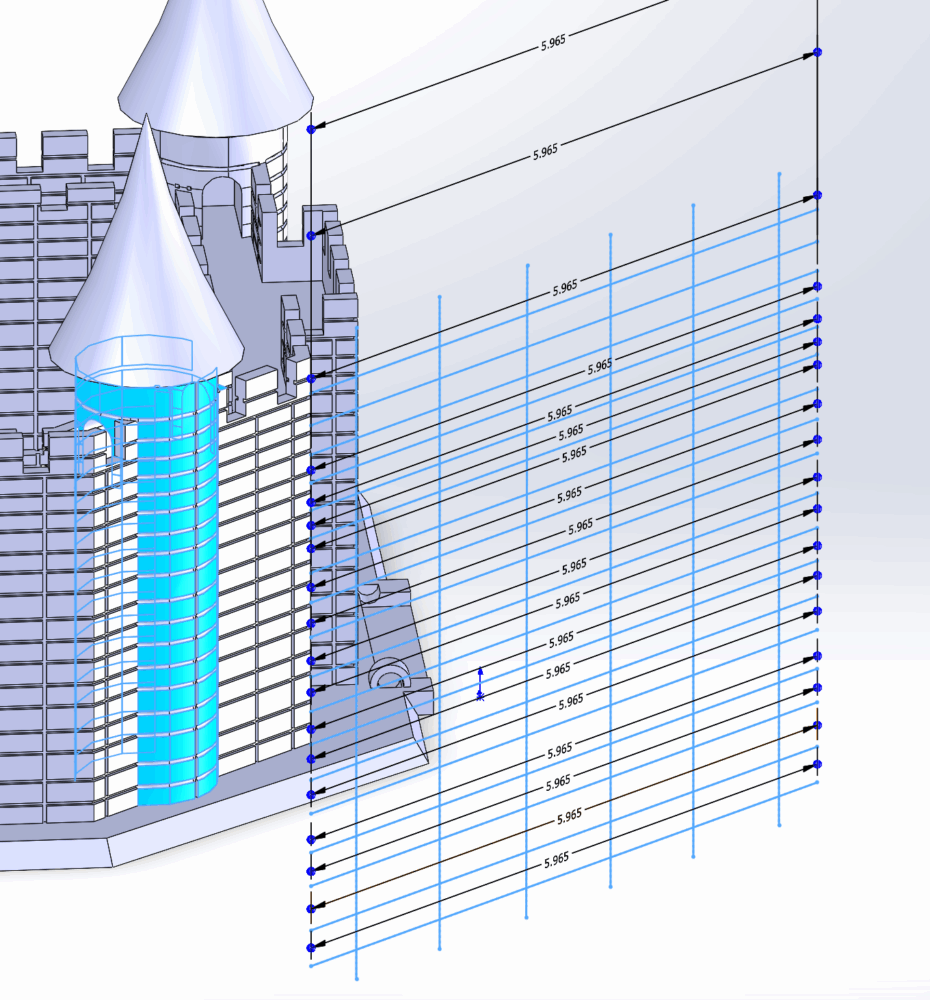
4. Most of my time on this project was spent on the CAD, mainly adding and revising lots of smaller details like the brick patterns, the drawbridge and its connections, the staircase, walkways, and more. In total I had over 900 sketches and 35 planes which I used to create all these details. The biggest time sink was creating all the brick patterns. To create these I just made sketches with many horizontal and vertical lines and then used a thin cut extrude to create them. This involves putting sketches on every face where I wanted these details, meaning that every corner required a transition to a new sketch. I also had to mirror these details across multiple planes to put them on both sides of the walls, and both sides of the top extrusions on the ramparts. The trickiest part was the cylindrical towers where I had to change my approach. I learned to wrap sketches around objects for the first time, and after wrapping these I had to used cut sweeps one by one on each line up and down the tower which was very tedious. You can see a wrapped sketch below.
Due to the sort of right angular nature to the whole design, lots of the creation involved drawing lots of sketches and the extruding or cutting them into the starting form. I made sure to design my project from the ground up to mostly print without needing supports, so this included things like adding chamfers to the underside of outcroppings at an angle that my printer could handle. And I have experience printing enough things that I know what overhangs my printer can do without supports. You can again see the final major CAD pieces below. 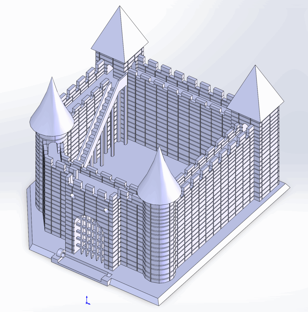
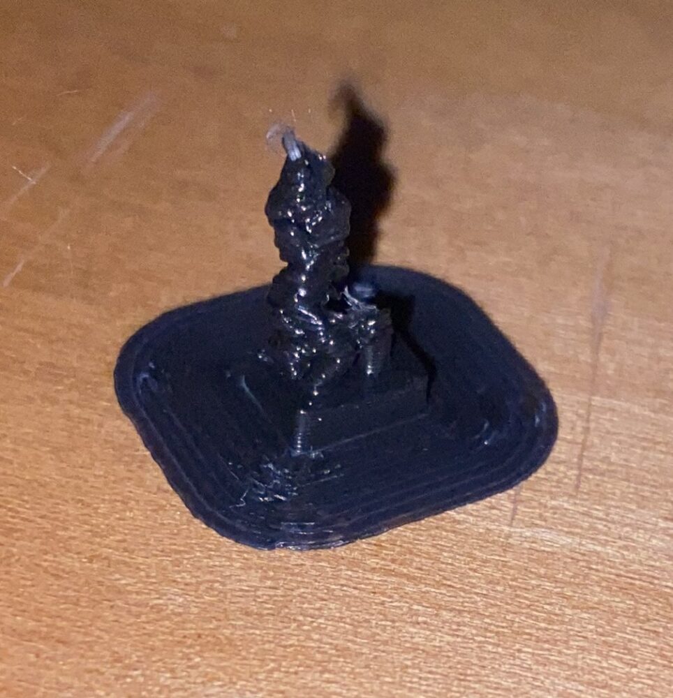
5. While I was working on the CAD I was also printing various pieces that I could test for compatibility and printability. This includes things like all the crank pieces which were simpler to CAD, and so I could print them earlier and test for things like mating issues, and just making sure the chain would easily wrap around it on its own. There are also many small extrusions in the project which were to be used to attack one chain link to and create a secure connection, so I needed to measure what the right balance was between printability and being small enough to wrap one millimeter-ish sized chain link around it. You can see the result of one of these such tests below, and this one clearly it didn’t turn out well.
6. Printing was the major next step after completing the CAD and feeling confident in it. I just talked about how I was printing smaller pieces as I went, but the main castle wall print took 28 hours, and was about 500g of PLA. AFter the main print was completed, I also had to work on removing some supports which were needed on the front checkered gate and that corresponding large arched entryway. You can see the complete and unpainted white print below with the bunch of support material noticeable coming from the gate.
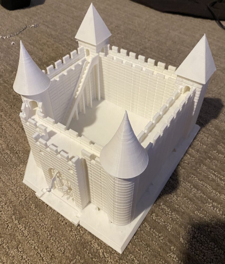
Removing these supports actually caused me to break off a couple of segments of the front gate, which I repaired using a soldering iron to melt the plastic back together (in a nice ventilated room).
7. From here I just needed to paint my major components. Of course, most of the walls would be gray, and I wanted it to be a relatively light shade so I combined gray with white. I have a collection of bottled paints which I bought a while ago and they are still serving me well for projects like this, with tons of different colors which I can combine to create even more. I just applied all the paint with brushes. I combined a blue with other white and dark colors to get the shade I wanted, similar thing with the wood color tone. I’ve only done one coat on the gray walls at this point and will plan to do another before the expo.
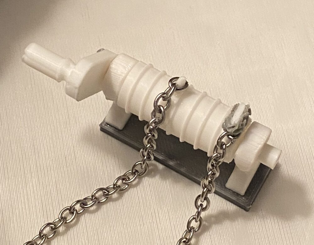
8. After I had the pieces printed and colored as I wanted I then had to connect pieces together, like two semi-circle pieces glued to the main base to hold the drawbridge in place, or the various crank components together, or the chain to the crank. In these cases I used a combination of glue (cyanoacrylate), a 3D printing pen to add material, and a soldering iron to melt the plastic to easily form it, and this additional material gives me a physical seal. You can see in the picture below and example of this one the right side of the crank where that gray material is plastic, added and melted to hold the white pieces together which the chain connected to. On the left side you can see that I felt glue was good enough for this one, and it maintains the hold well.
9. The final piece was sizing and attaching the chain to the drawbridge. It needed to be the right length to look relatively taut when the bridge was down, made trickier by the fact that the distance between the placement of the chains on the crank and the distance between where the chains went through the walls was different, so I had multiple iterations of messing around with connecting and disconnecting links until I felt they each looked about the right length. You can see my connection points in the below image, I just used big dabs of glue in this case and it seems to be a reliable connection.
![]()
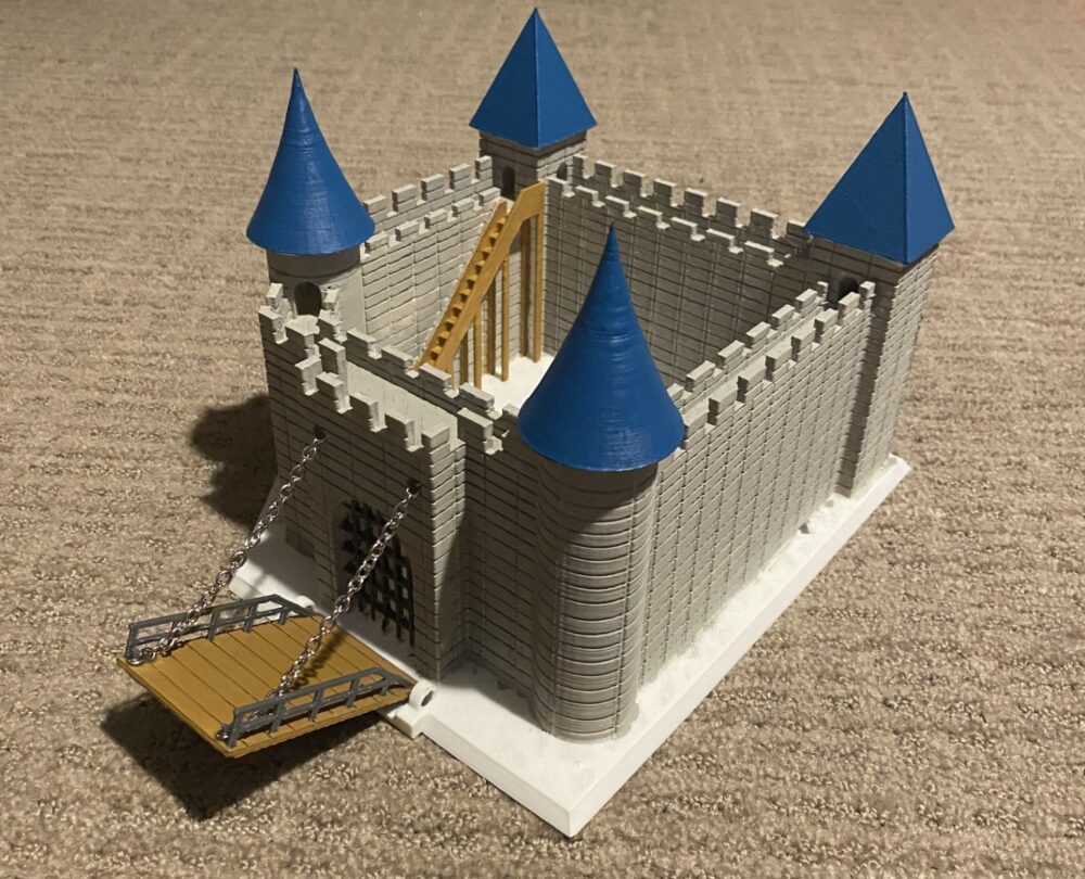
You can see the final product to the right again, and overall, I am quite happy with the results. Functionally, my dynamic piece was just the drawbridge, and it works about as I imagined it. I’m still not sure exactly how I want to fix the crank, though, so it requires holding it and making sure that the chain wraps where it is supposed to as it turns. But overall, I’m not concerned about improving functionality. My project was almost purely an aesthetic one, a 3D printed sculpture if you will, and in that sense I think it looks quite appealing. The colors work well together, and it almost perfectly matches my initial vision for the project, and I would say that it meets the specifications I laid out in my previous post. The one major question is what I will do with it now. I think there is room for this base to be improved or added upon. Early in the process I was thinking about what could be on the inside of the walls instead of empty space, but due to time constraints I just decided to focus on the exterior and make that as I envisioned, which I think was the right call, but I wish I had started the CAD in earnest earlier so that I had more time to play with different interior design concepts. Moving beyond this class, I think I will continue to iterate on this project. There is plenty of room for added decorations (like banners or flags) which I could just glue onto the project as it stands. But I think I will think about having something (whether a livable castle, stables, smaller houses, etc.) on the inside. I hope to be able to just print something separately and place and glue it to the existing base, but the great thing about CAD and 3D printing is that I can just keep iterating on the CAD model and print it again, it would just cost me a few bucks. But I am grateful for this class giving me the opportunity to stretch my skills and make something artistically I can display and be proud of, which I might not have done on my own.