
For my primary design project, I chose to fabricate a custom set of front suspension uprights for my 1965 Ford Mustang race car. In my previous post, I outlined the design methodology I followed, which began with establishing a set of requirements that guided my decision-making throughout the development process. Key factors influencing the design included the selection of wheel hubs, the brake system configuration, wheel diameter, target kingpin inclination, desired caster trail dimensions, scrub radius, and the fixed geometry of the control arms. With these parameters in place, I proceeded to create a SolidWorks model of the upright that met all of the specified design criteria.
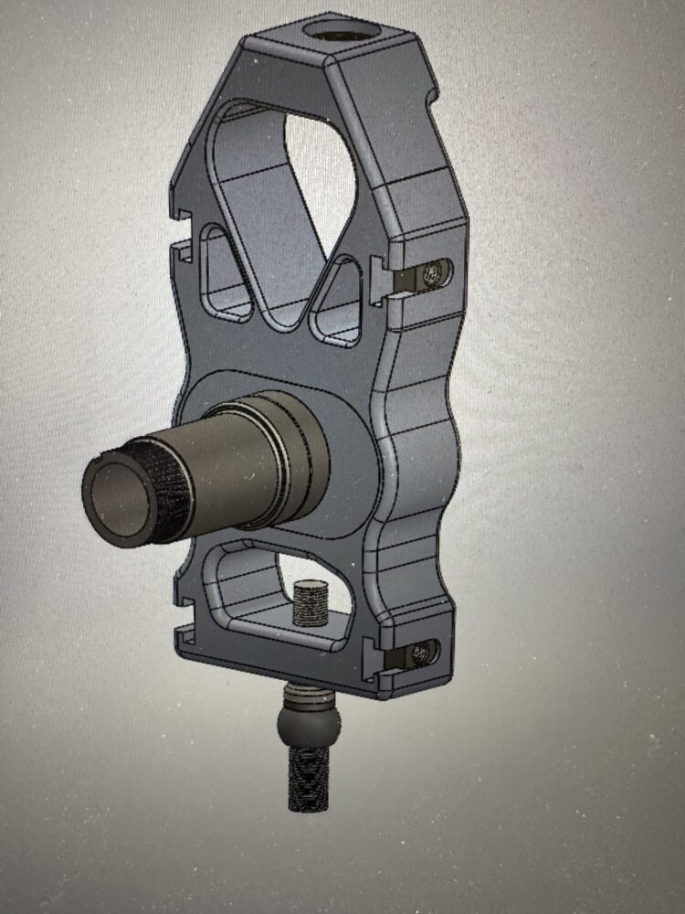
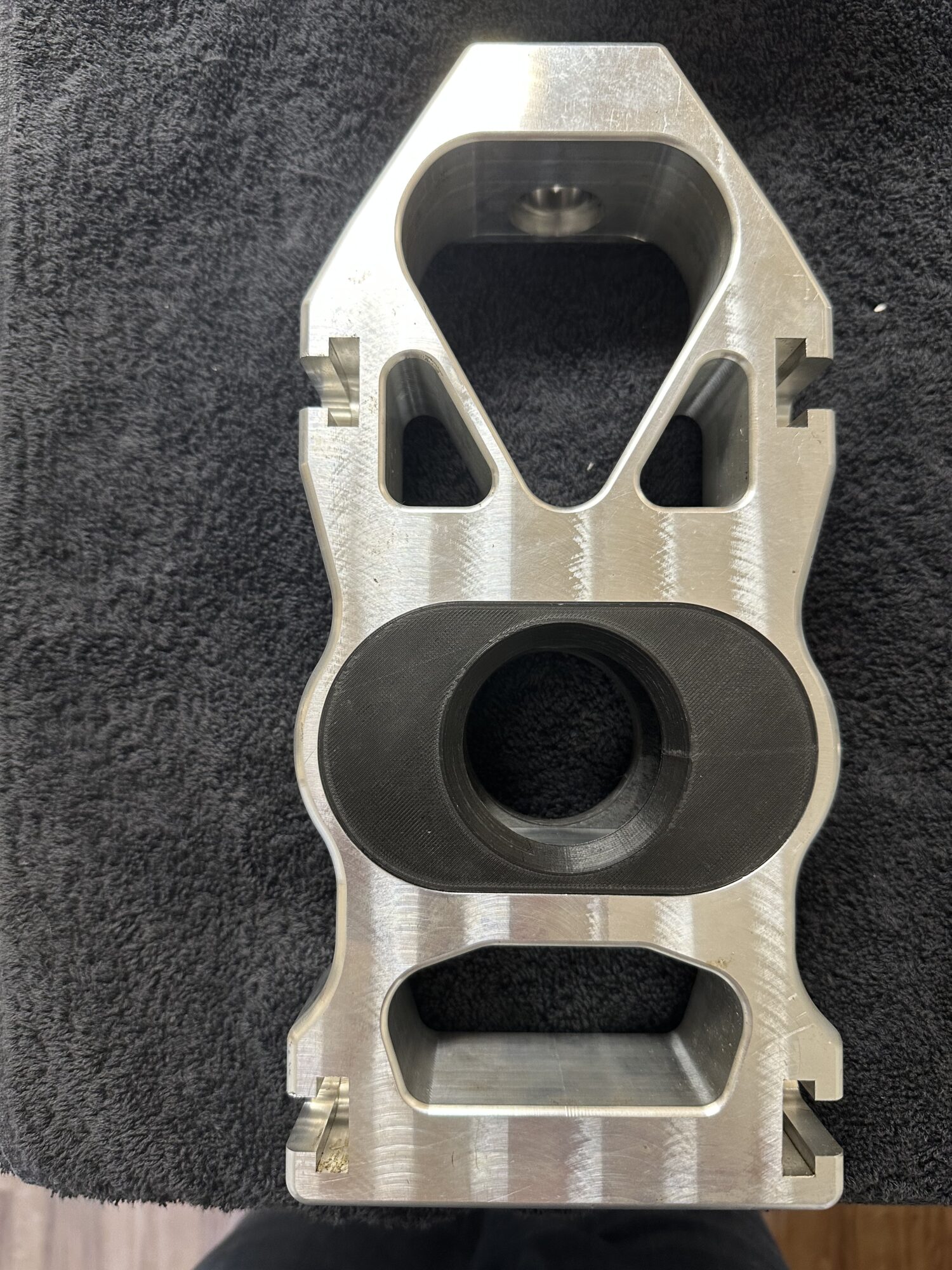
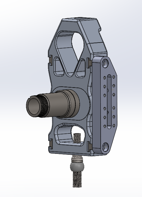
The image above depicts the completed solid model of the front uprights, which includes the upright body, adjustable spindle keys, spindle pin, and retaining nut. I selected 7075-T651 aluminum bar stock for the upright body and spindle adjustment keys due to its favorable combination of light weight and high strength. For the spindle bearing pin and retaining nut, I opted for 4140 chromoly steel to take advantage of its superior strength and wear resistance. However, I’ve encountered difficulties in sourcing the 4140 material at a reasonable cost, and accessing a CNC lathe capable of machining the hardened steel to spec has proven challenging. As a contingency, I revised the manufacturing approach and produced the spindle pin and retaining nut from plastic as a prototype in order to meet the Expo deadline. On a more positive note, I was able to successfully source the aluminum for the upright body and keys, and I completed the CNC machining operations on these parts using a 3-axis mill owned by a friend.
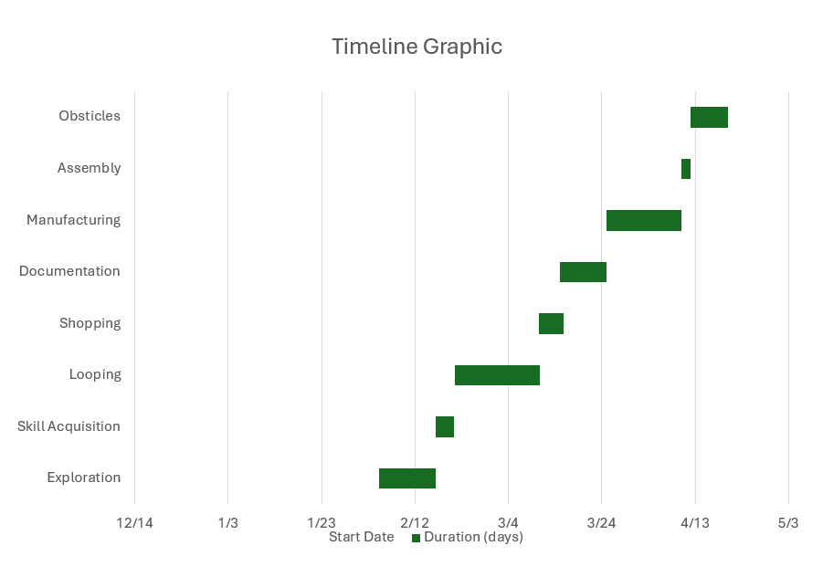
The figure shown below outlines the approximate timeline I have established to complete the project. This timeline accounts for earlier phases that I have already finished, including the exploration stage, skill development, sourcing of materials, and potential obstacles. During my design process, I documented all machining tolerances to ensure that each component would assemble smoothly and without issue. The next phase was manufacturing, which commenced once the necessary materials were received and the Mastercam program had been finalized for machining the parts. I have set aside a brief period for the spindle assembly, followed by a longer buffer period to address any unexpected challenges that could have risen. These potential obstacles involved complications during manufacturing or difficulties with assembly that impacted the overall timeline of the project.
The image above shows the initial machining operation for the rear spindle keys on the CNC mill. I ultimately chose to produce three variations of spindle pin offset: a centered key, a 0.5-inch offset key, and a 1-inch offset key. These offset options will allow me to evaluate the race car’s performance across different caster trail settings and determine which configuration yields the most responsive steering behavior. The next step in the manufacturing process involved machining a set of soft jaws to securely fixture the keys upside down in the milling vise for the second operation.
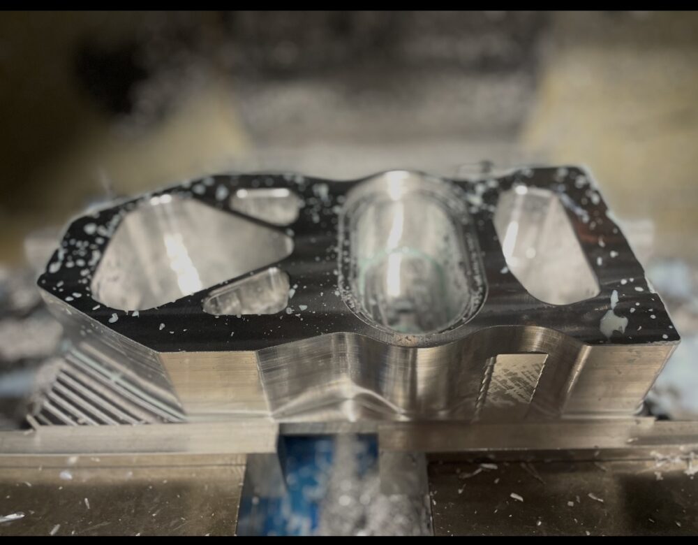
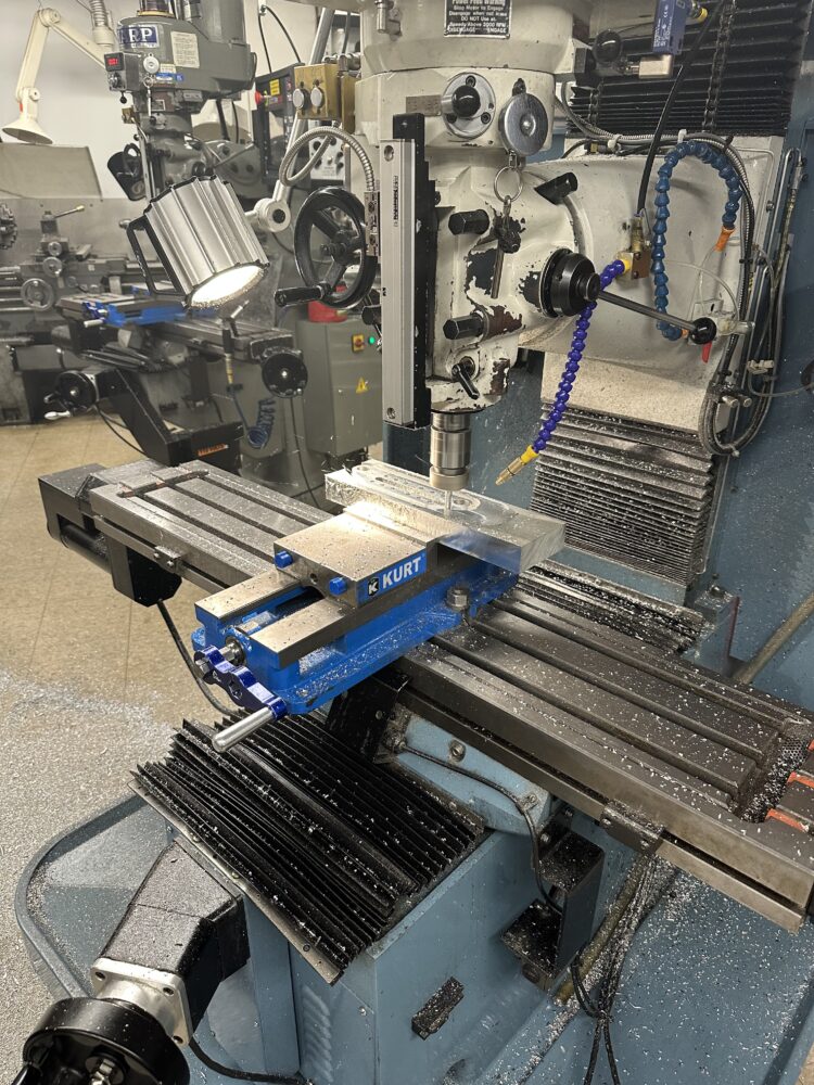
The image above illustrates the first CNC milling operation in the production of the aluminum upright body. Due to the complexity of the component, the manufacturing process involved multiple steps, with certain features such as the bore for the spherical mono-ball bearing located at the top of the upright. This feature required being completed using manual milling operations. Given the intricate geometry, the upright body was the most time-consuming part to produce in this project.
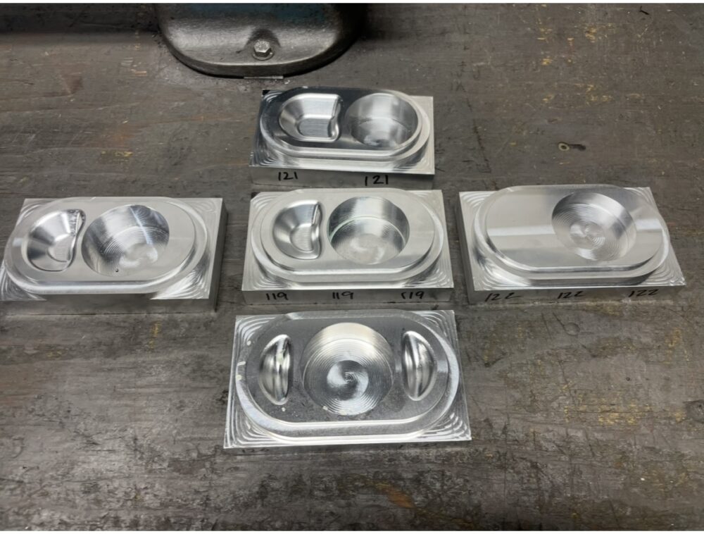
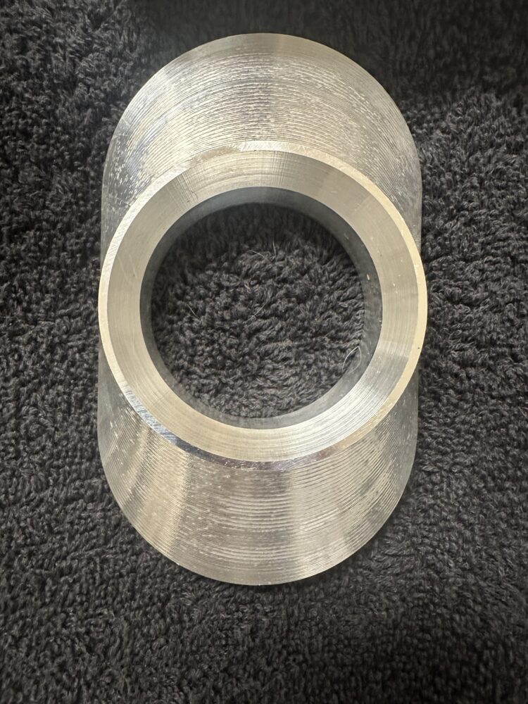
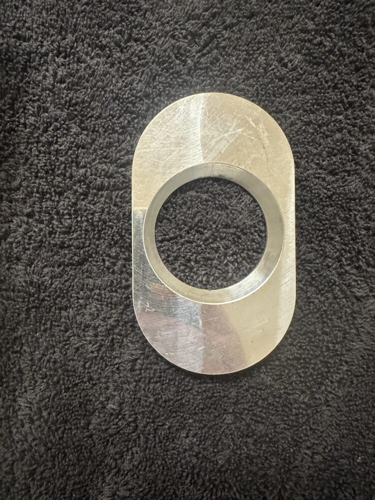
The images below show the finished caster trail keys after machining. I was impressed with the overall quality of the machining and the only required post processing of the components was to file the edges of the keys to allow for a tight slip fit of the machine keys into the upright body.
As a later addition, I opted to broaden the scope of my project by designing the steering arm that connects directly to the suspension upright. The main motivation behind including this part in the final design stemmed from having access to the CNC mill in the ITLL machine shop, which made fabricating this component both practical and efficient. Beyond the convenience, incorporating the steering arm into the assembly for Expo helps convey a clearer picture of the project’s overall functionality to the audience. The image below highlights my SolidWorks model of the steering arm. You’ll notice that I was able to maintain the same aerospace-inspired aesthetic consistent with the rest of the project, and I selected 7075-T651 aluminum stock as the material for its favorable properties. The steering arm is fastened to the upright using T-nut hardware, which I expect to receive by mail in time for Expo so I can present the complete assembly.
The image shown below illustrates the multistep machining process of the steering arm. Most of the machining was performed using a 3/8 endmill and the total processing time of the part was an hour.
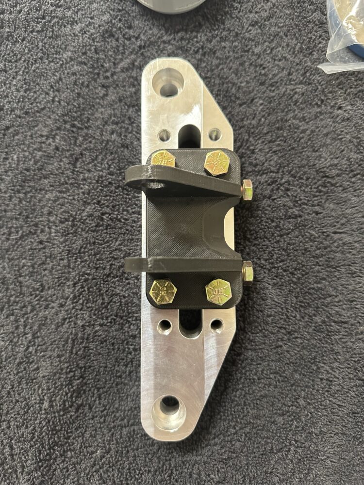
The final steering arm is shown below. Notice that the actual 3D printed mount located on the steering arm is adjustable with the presence of the multiple hole pattern on the machined component. This feature will allow for adjusting the mount height of the outer tie rod to solve any bump steer issues. Additionally, the use of the T-nut slots on the upright to interface the steering arm allows for the upright to be non-specific to the driver or passenger side of the car. This allows for a more modular design of the vehicle.
Looking ahead, there are a few key updates I’d like to implement before this project sees use on the race car. First, components currently 3D printed, such as the spindle pin and its back nut, will need to be machined from 4140 steel for proper strength and durability. In addition, the tie rod mount on the steering arm should be fabricated as a steel weldment, which means I’ll need access to a CNC plasma cutter or waterjet to produce the required sheet metal flat patterns. Lastly, I plan to incorporate a standard K-727 Chrysler lower ball joint stud, which will involve machining a corresponding tapered hole into the bottom face of the upright. I’m looking forward to tackling these updates over the coming months.