
After some shipping delays, I finally completed the assembly of my project. I was able to get the aluminum tubing I needed just in time to manufacture in slots, and my project came together just how I envisioned it. With that, this post will describe my entire process of building out my bedframe. The goal of this was to have a rustic modern aesthetic. The bedframe was to fit inside of a shuttle bus that I have been building out, which is an outdoor adventure rig. I already have a wooden theme going, so I wanted my bedframe to match both the color and feel of this. I also wanted simple functionality, and I took a great deal of inspiration from Ikea-style bed frames. For the dynamic component of this project, I wanted the bed frame to telescope into itself. I also wanted to include dressers in the frame of the bedframe to give functional storage to my build. With that, I had to select the proper cabinet size to fit the constraints of my bed and the building space in the bus. This design process is detailed in my part one post.
Once I got my cabinets from Home Depot, I had to assemble them. The cabinets shipped as individual pieces, with an instruction manual on how to assemble them. I followed these steps, but I made some modifications to fit the cabinets to the interior of my bus. For example, I needed to cut out a corner in one of the cabinets to fit around a box that encased part of the gas line in the side wall of my bus. I did this by marking out the measurements onto the specific cabinets and then making the cuts in the ITLL woodshop.

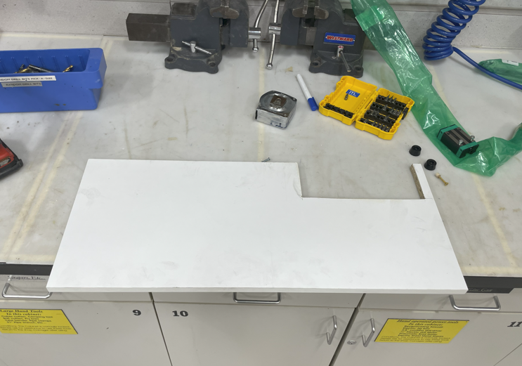
Image 1 and 2: The pieces of the cabinets as they shipped and the cut modification I made
Once this was complete, I assembled the cabinets outside of the bus to get them ready to move in. This was a straightforward process, and I did not even need any tools outside of what came in the hardware kit for the cabinets. From here, I was able to analyze the built cabinet and visualize how it would fit inside the bus. The plan was to have these cabinets form part of the wooden structural frame for the base of my bed system.
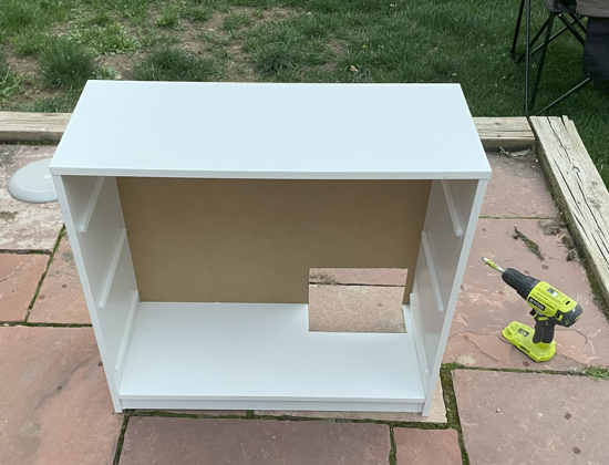

Image 3 and 4: Built out the cabinet with the cut modification I made, and then both cabinets with the drawers installed
The cabinets accounted for half of the supporting bed frame base structure, but I needed to add additional support for the entirety of the bed. I used more 2x4s for this. I was implementing 2 support legs and 1 runner going over the top of them. These would ultimately be fixed to the cabinets to sit flush and form one solid structure. To get these legs cut properly, I measured out the height of the cabinets and the distance needed from my cabinets to the back wall. I then went to the ITLL woodshop to cut and sand these 2x4s. Finally, I painted over them to match the interior colors of my bus. This was to create a feeling of uniformity and add to the simple modern aesthetic I was going for.
.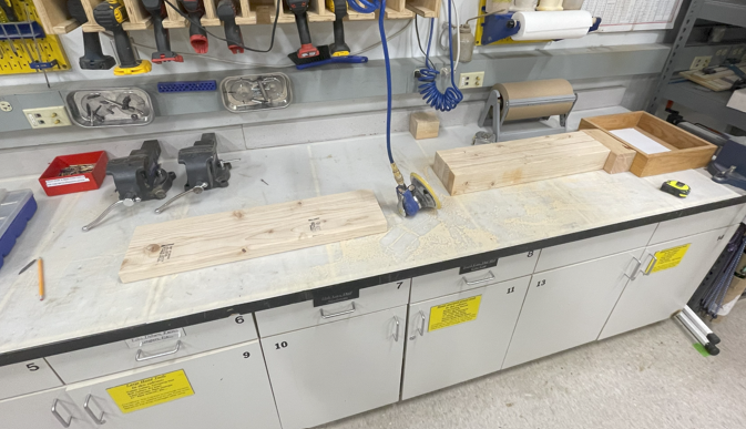
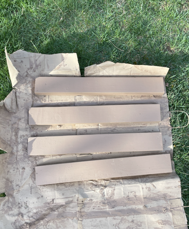
Image 5 and 6: The wooden stilts and runners being sanded, and then the final paint job
From here, I needed to fix the cabinets into my bus. I started by using 2×4 wood cuts to create a cleat system for the cabinets. I fixed these cleats into the wall, where I had wooden runners, as well as into the floor. I measured out the spacing of the bottom of the cabinets to see exactly how large and spaced these 2×4 cleats needed to be. I then slid in the cabinets to sit flush among the cleats, and I double-checked the spacing of the cabinets. Once this was confirmed, I attached the cabinets to the cleats as well as the wall. I made sure to predrill all of my screw holes to avoid splitting the wood, and I used wood 2″ wood screws to go through the sides of the cabinets and deep into the securing wood. I then did the same thing with the 2x4s I cut out and secured the rest of the base system to connect with the cabinets and the wall. I also used a tether system that came with the cabinets to secure the top to the wall of the bus. This resulted in one final piece that was structurally sound and secured to the bus itself. I felt confident that this base system was not going anywhere. I tested this by standing and jumping on the base system.
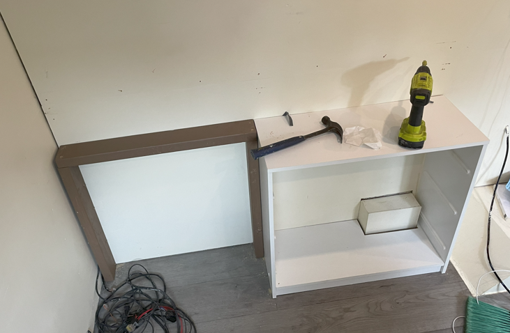
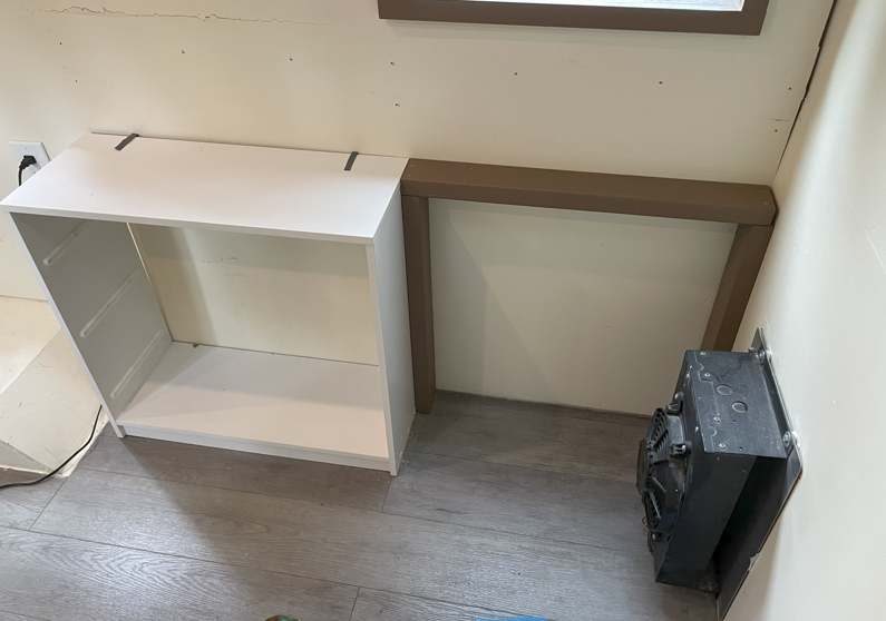
Image 7 and 8: The base frame system I made from the cabinet and 2x4s on each side of the bus
I now had a solid base system to build the beams and sliding system of my bedframe onto. I first needed to fabricate the sliding rails that I purchased to fit exactly the length I needed. I measured the total length of my frame system to 55″ after it was assembled. This was the length I was going for. I then took the sliding rails to the fabrication shop in the ITLL and cut them to this length. The casing for the rails was made of aluminum, but the rails themselves were made of hardened steel. I had to unscrew the rails from the casing and cut them separately, as they were a much harder material.
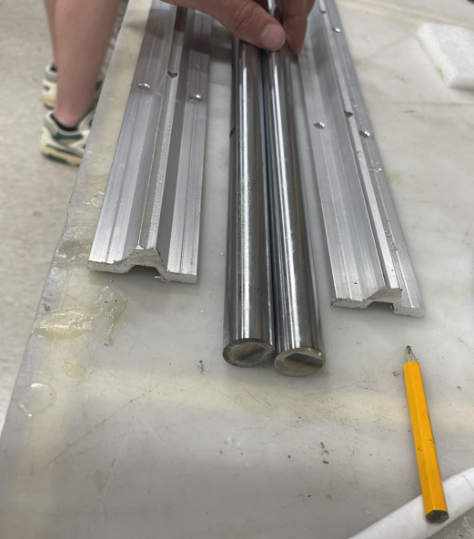
Image 9: The sliding rail components after I finished cutting them
While I was in the machine shop, I needed to add my slots for the aluminum beams that I purchased. These slots needed to match the hole pattern of the sliding blocks that would go on the sliding rails. I used a dial caliper to obtain these measurements, and then I created a drawing to bring to the shop. I then used a mill to cut out the slots at each end of the tubing. Finally, I cleaned and polished the beams so that the aluminum could have a nice clean finished look. This would ultimately help with my minimalist aesthetic for this build.
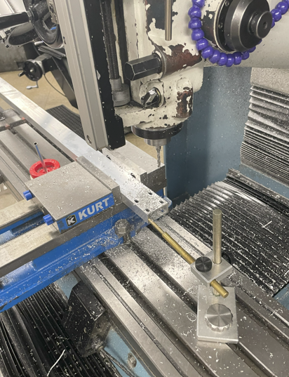
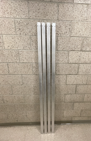
Image 10 and 11: The milling process and final polished look for my aluminum tubing beams
Now I had everything I needed to add the sliding component to the bed. A big consideration I had with this build was the alignment of the rails on top of the bed frame. This was something that required a high amount of precision in order for my project to function properly. To achieve this, I took a unique approach. Instead of using measurement to get consistent alignment, I set up one of the beams on both pillow blocks. I then slid it onto the rails and marked where the positioning needed to be on each end of the rails on top of the wood base. This way, I knew that the positional distance between the beams at each end would be the same. With these positions marked, I then screwed in the slide rails to fix them into place.
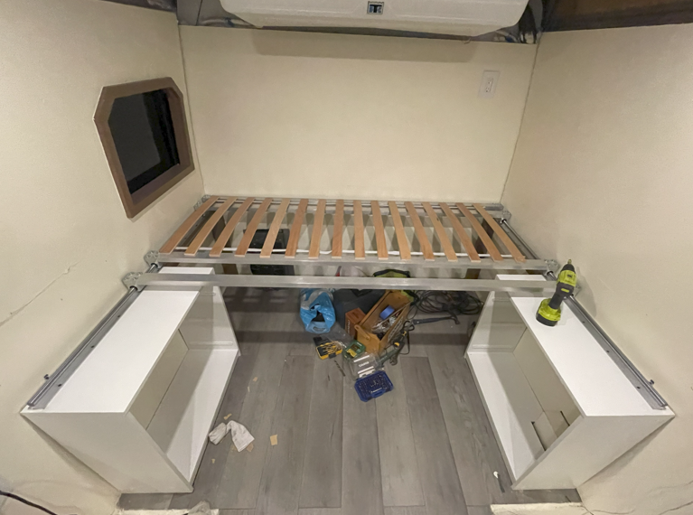
Image 12: The bed system with the rails secured in place. You can see the independent rail I used for alignment
At this point, the bed frame was almost complete. Now I needed to integrate the beams and create the telescoping component with interlocking wood slats. I did this by screwing in all 4 beams into pillow blocks on each end. I did a loose screw fit so that there was room to adjust the beams before fully seccuring them onto the sliding rails. I then slid the beams with the pillow block onto the slide rail and ensured they were able to slide straight. Once I configured the positioning to allow for this, I tightened the screws fixing the beams into the pillow blocks. I was left with 4 independently sliding beams that could move across the slide rails with minimal friction. For the final part of the telescoping bed frame, I attached wooden slats to go between the beams. I did this in an interlocking fashion, with beams 1 and 3 being interconnected, and beams 2 and 4 being interconnected. This allowed for beams 2 and 4 and their interconnecting slats to fit in with the wooden slats connecting beams 1 and 3. The telescoping mechanism worked perfectly, and I was able to extend the bed out over the cabinets, then collapse it in half the width. In the collapsed configuration, I could access the drawers of my cabinets, and I achieved the full functionality I intended with this build.
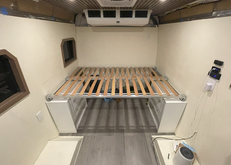
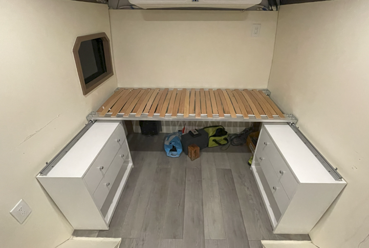
Images 13 and 14: Final bedframe in the extended and collapsed configurations
Overall, I am so happy with how this project turned out. I was a little nervous with the timeline of the build, as my beams came in last minute. However, I was able to get everything put together just in time. I think the project matched my aesthetic very well. The wood slats give it a simple and rustic feel, and the sliding system makes it functional with minimal clutter. I am so proud of this project!