
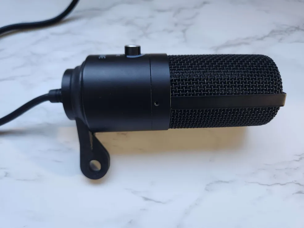
For my final project, I created a minimalist, sleek, low-profile boom arm inspired by those currently available on the market. I scaled my boom arm to match the length of my table, as I happen to have a table with a shorter depth than most (I do not have the exact measurement). I used a Markforged printer to print part of the boom arm and purchased hardware to assemble and hold the parts together. The overall length of the assembly is approximately 15.9 inches in its longest configuration, set at a height above the surface of the table that is suitable for picking up my voice while sitting. This boom arm is designed to hold my current microphone and to blend seamlessly with the rest of my setup, hence its minimalist appearance.
Materials
As for the arms and table mount of the mic boom arm, they are made from the filament used in the Markforged, specifically Onyx, which is essentially a mix of nylon and carbon fiber. I could have opted for a lighter material or machined the piece out of metal to save money or to use heavier, higher-quality materials that would last longer. However, I chose Onyx due to the strength it provides at a lower price. It also offers a clean surface finish compared to regular PLA available at the ITLL, so post-print processing wasn’t necessary. Another benefit is that Onyx is naturally black or dark gray, which fits well with my sleek color scheme and matches my aesthetic.
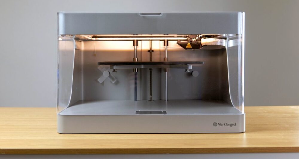
Image [1]: Markforged 3D Printer
In terms of the hardware used to assemble the low-profile microphone, I utilized the following hex nuts and materials to ensure that each component fit together correctly and was securely attached to my table. Here is a list of those items:
- 5/8-11 Hex Nut
- 3/4″-10 Hex Nut
- Neoprene Sponge Foam Rubber (12 in x 59 in x 1/16 in)
- Ratchet
- 1-⅛” Impact Socket
- 27 mm Impact Socket
Table Mount
In terms of building the table mount component of the design, I used SolidWorks (CAD software) to create it. I focused on specific dimensions for the table mount, ensuring it could sit on my table without taking up too much space. I chose a footprint of 2.5 inches by 2.4 inches, which was determined by eyeballing the space with a caliper at the edge of my desk to see how much room it would visually occupy. For the height, I selected a distance of around 3 inches, keeping it similar to the Facebook print, as I didn’t want the structure to stand out too much. A shorter height would be less visually intrusive on the table. Regarding the threads, they are modeled after a .625-11 thread within the CAD software and extend 0.5 inches down from the protruding column. There is a hole at the bottom that uses a similar thread to the one on the top side, creating a tactical and threaded column that should theoretically screw into one another when the parts are assembled. The top side is designed for interaction with the first arm, while the bottom hole is meant to connect with a threaded standoff that I purchased from my local hardware store.
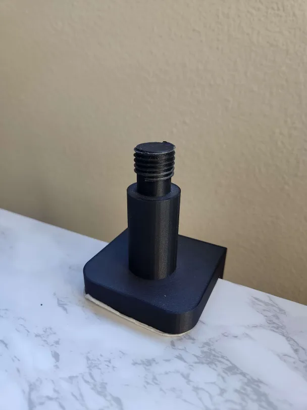
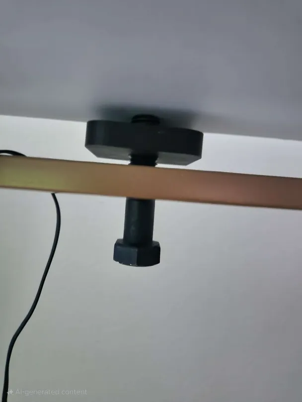
Image [2 & 3]: Printed Table Mount
An issue I encountered during the making of this project was that the threads created in the CAD software did not match the threads printed by the Markforged. This discrepancy is due to the tolerances at which the Markforged can print, and the creation of threads is a delicate process. As the filament tends to contract or expand during cooling, the desired dimensions can change, which is something I didn’t account for when ordering parts initially. As a result, my original hex nut of ⅝”-11 was unable to thread on properly, as the filament had expanded beyond what I originally scaled it to in the software. However, I quickly used a socket/hex nut thread measurement table at the ITLL, specifically in the project depot, which allowed me to determine the correct threading size I needed. This turned out to be a ¾”-10 thread.
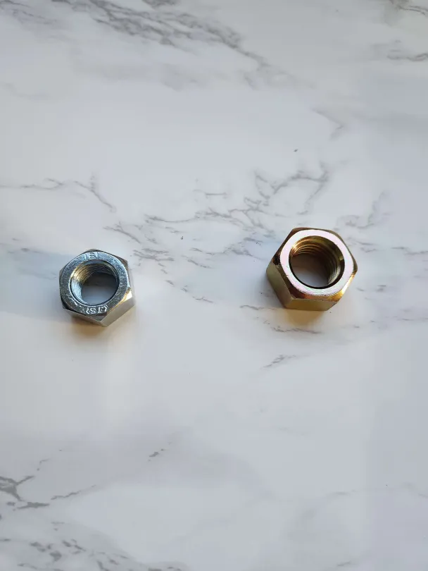
Image [4]: Hex Nuts
First Arm
Now, for the first arm of the boom arm assembly, it has a sitting height of approximately 2.5 inches and a length of around 10.5 inches. Designing this arm was relatively easy, as I simply needed to reference the previous part of the table mount to determine a proper diameter for the hole that would fit securely on the lip of the table mount column leading up to the threaded section at the top. This essentially recreated a connector and receiver relationship between the two parts. I also had to figure out the diameter of the threads that would be added to that top portion, ensuring that the arm hole could fit over that part of the column without going over the entire column. A small section view of what I am referring to is shown in the image below:
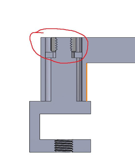
Image [5] Hex Bolt sitting flush with surface
Though I was using the dimensions provided after printing, I discovered some slight differences between my CAD model and what the Markforged printer was able to recreate. Another challenge I encountered while creating the first arm of the boom microphone assembly was related to the Expo, as shown in the little gray section of the image. If the Expo is tightened all the way down, there is little to no space for me to use a tool or my hands to loosen it if it is accidentally over-tightened.
To address this issue, I needed to find a method to elevate the Expo slightly off the surface. This involved purchasing a washer to place between the two surfaces, adding some extra thickness and allowing a socket wrench to latch onto the top portion for tightening or loosening. This theme of needing additional space for proper tightening without a socket wrench also occurred with other components, such as the table mount. Below is an image of the washer:
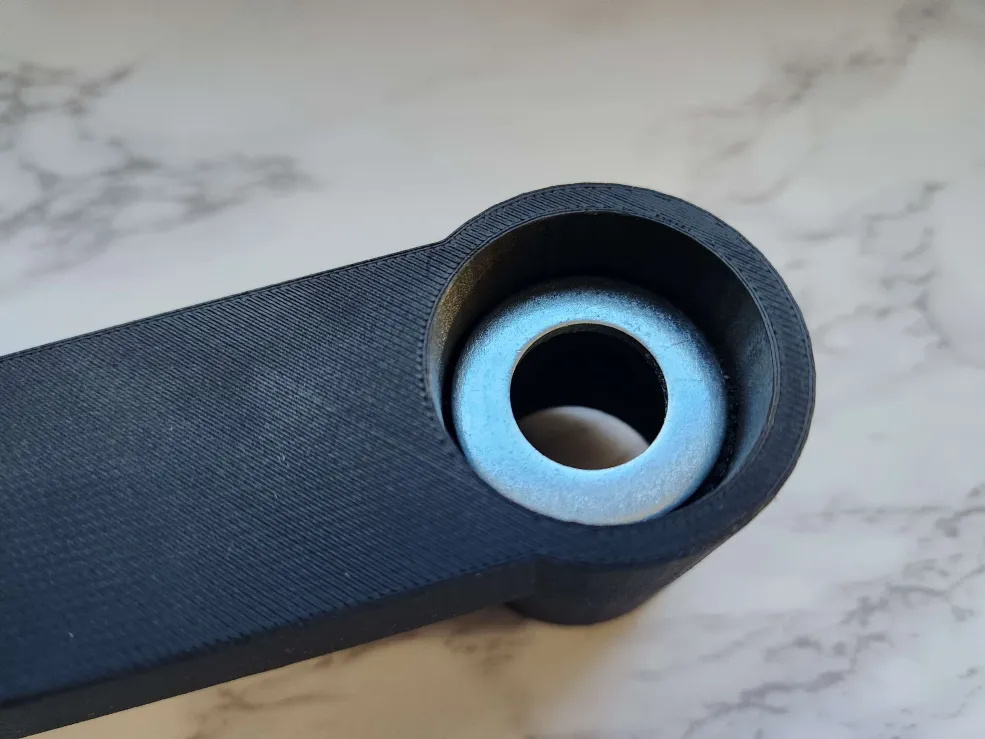
Image [6]: Washer in First Arm
Second Arm
The fabrication of the second arm turned out to be the longest and most drawn-out process due to my previous experiences with issues related to printing threads on the Markforged printer. The expansion of those threads affected the hex nut that needed to be ordered to ensure it could be tightened onto the rest of the assembly. To address this issue, I used a thread measurement tool available at the ITLL and visited a hardware store to test hex nuts that would fit the thread measurement. This approach helped me avoid bulk ordering unnecessary hex nuts that would have been left over if I had continued to order them online through Amazon.
In terms of dimensions for the second arm, I went through many iterations during the design process, primarily focusing on fine-tuning elements already present on the arm. One example of this is the mounting hole for the microphone, which was originally set too far into the arm, preventing the extended part of the microphone from reaching it and locking in place. I also realized that the geometry inhibited the vertical movement, so I needed to smooth out that edge instead of having a flat edge, leading me to the third and final design. The mounting hole had to have an indented surface to allow the hardware to sit flush with the surface of the arm. This is shown in the images below:
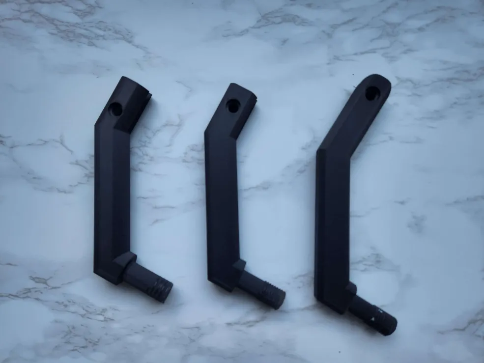
Image [7]: Iteration of Second Arm
Image below show the mount hole on the microphone that is meant to lineup hole on the arm and the hardware for mounting and positioning the microphone and the inner second surface that aids in the hardware being able to connect and sit flush with the surface/body
 :
:
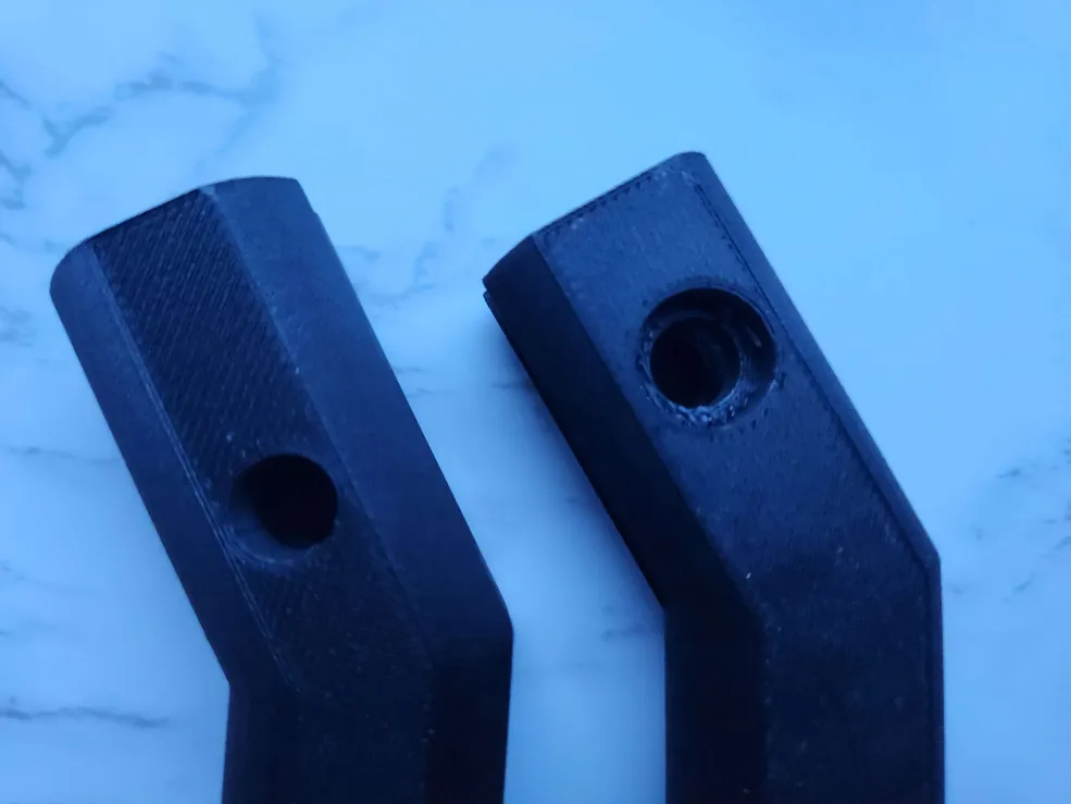
Image [8 & 9]: Mounting hole and interfacing surfaces
Another aspect that was iterated on throughout the making of the arm was the threading at the tail end. Originally, I had looked up a YouTube video that suggested scaling the model up to create a thicker surface area for the threads. However, I realized that this method of scaling up and having thicker threads, along with the threads being spaced apart, needed to interact with a piece that has a tapped hole made in SolidWorks using a similar process. Therefore, I would need to ensure that both the hole for the hex nut and the threading were the same, and I would have to print both pieces. This was something I wanted to avoid, as I had already purchased hardware and wanted to use it in my project.
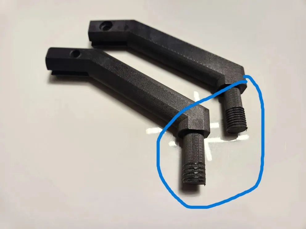
Image [10]: Change in threading
Assembly
In terms of assembly, I used both the hardware in conjunction with some tools, specifically a couple of impact socket wrenches, to tighten sections of the arm and secure the table clamp at the bottom. This was necessary because the printed holes with threaded walls had difficulty interacting with machine-thread components, primarily due to the tolerances between each component.
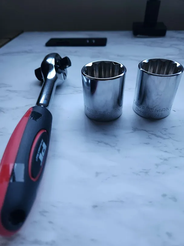
Image [11]: Impact Socket and Ratchet
Foaming
Something I installed to reduce vibrations picked up by the microphone was a piece of foam, or multiple layers of rubberized material. This not only provided grip on the surface but also helped dampen some of the vibrations that could transfer through the material. Since I am unsure of the properties of onyx in relation to vibration, I hoped that adding multiple layers of foam would absorb some vibrations before they reached the microphone capsule. I encountered an issue with the interfacing surfaces of the microphone arms, specifically between the first and second arms. I had originally placed a layer of foam between the two arms, but the action of rotating the arm caused wear on that surface, tearing through the foam and rendering it essentially useless.
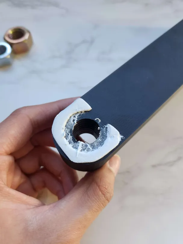
Image [12]: Destroyed Foam layer
Another issue I encountered was with the hardware I selected specifically for the table clamp. Over-tightening the hex bolt I bought from the hardware store posed a risk of harshly gripping onto my table, which could either scratch or crack its surface. Below is an image showing the damage caused to my table during the mounting of the microphone:
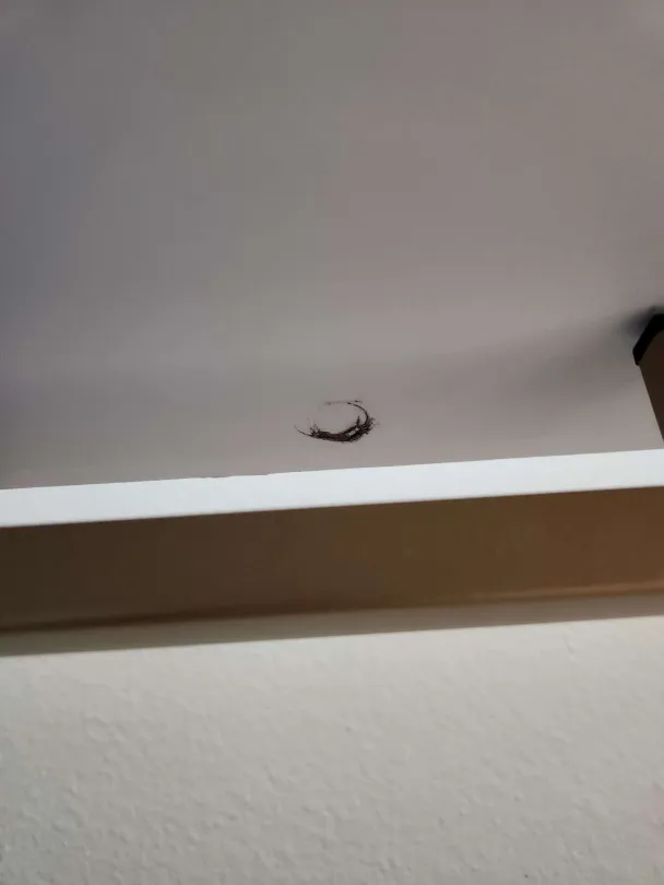
Image [13]: Hole cause from table clamp
Final Result and Opinion
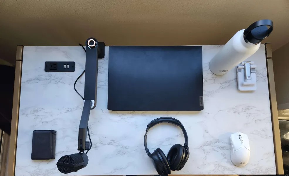
As a final result, I feel that overall it visually looks the way I wanted it to. It has a very minimal design that matches the aesthetic I aimed for, ensuring it doesn’t get in the way too much. It also fits well with many of the components I have, as it contrasts nicely with my table and other items, which happen to be black and white. Additionally, it conceals itself pretty well due to the color, blending in among the other black objects on my table. I am disappointed that I was unable to get to other portions of the project, particularly my desire to spray paint it a cream color. Ultimately, I think that might have gone in the opposite direction and made it stand out more, as lighter colors reflect more light and are easier for the eye to pick up. There are other aspects of the project that I wish I could have implemented or at least tried to implement during the semester. For me, this is going to be an ongoing project, and I want to improve this design to make it properly usable for someone other than myself.
Future Works
Some future improvements for this project would include not only adding foam to the table surface where the mounting arm is placed but also printing a threaded adapter that could interface with the existing threading. This adapter could terminate in a larger surface area, such as a cone or a flat rectangle, to spread out the pressure and prevent it from punching through like the current hardware. Another aspect that people have commented on, and which I want to try to implement, is addressing the issue of the cable dangling around the microphone arm. One suggestion made during my presentation was to incorporate a hook or to design a groove along the body on the opposite side to clip the cable in place. This would allow the cable to be neatly tucked away until it reaches the other end, where I can wrap it back around my laptop, improving cable management and making it look much cleaner. In terms of mitigating the damage done to the foam on the interfacing surfaces, I believe that adding a washer there would solve the issue. This would allow me to add different pieces of foam while providing peace of mind that the layer of metal would still enable the microphone to rotate about that point without damaging the foam. Hopefully, this would allow the dampening effect I am envisioning to take place.
Overall, I believe I still have a lot of work to do in terms of design and proper functionality. Although I am sad that I wasn’t able to complete this during the semester, I hope to continue working on this project throughout the summer.
Images cited:
3D Printing Industry. (2022). Markforged Printer. 3D Printing Industry. 3D Printing Industry. Retrieved 2025, from https://3dprintingindustry.com/news/review-markforged-mark-two-a-champion-of-composite-3d-printing-211627/ .