
Product Introduction
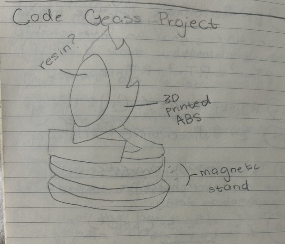
My final project is a helmet based on the accessory of the protagonist in the anime Code Geass. This item will stand on a magnetic levitation display that will slowly rotate the object while levitating it using a permanent magnet. This object is intended as a gift for my boyfriend who loves Code Geass and is a giant physics nerd. My primary project aesthetic is futurism. My aim was to create an object that feels like a showcase of technology. An object that naturally arises curiosity surrounding the physics of its operation as well as being sleek and beautiful.
My initial vision for the project is shown in my rough sketch below.
Product Development
The Circuitry:
I bought a DIY magnetic levitation kit from Etsy for this project. I would not exactly recommend this as a strategy as there is critical IC labeling info missing and no assembly or schematic provided so I’ve had to do a lot of reverse engineering. It looks awesome though.

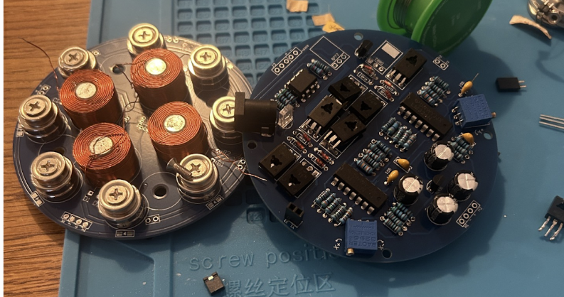
I hand-soldered every piece to the two PCBs, at some points using reverse image search on google to get different angles on what the finished PCB should look like. Honestly, this was really fun, it felt like solving a puzzle, but with more soldering.
This project involved attaching many transistors to SMT heat-sinks (see the big pads above). It was quite challenging to get the heatsinks hot enough to melt solder without damaging the transistors with the heat gun. Several burnt out and needed to be replaced leading to delays in the development process.
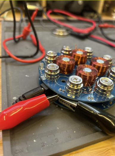
This circuit also needed to be finely adjusted after construction. Tuning the potentiometers doesn’t directly “strengthen” or “weaken” the static magnetic field but changes how the control system adjusts the magnetic field dynamically to maintain levitation. The module essentially uses the potentiometers to fine-tune the real-time balance of forces via coil current. In order to tune the circuit I had remove the jumper flags (aka shorting clips) and place a DMM in the current path. By adjusting the potentiometers until current was near zero in this path I was able to adjust the baseline level for coil current.
A primary focus of this project was on power. I wanted the object to be battery powered at first because I thought this enhanced the futuristic illusion. If the user couldn’t see the power system, perhaps it would seem more magical. I used a 3D printed battery case to allow the user to toggle power on and off, and the baseline tuning to minimize coil current when no magnet is present. This PCB required 12V and up to 2A. Initially I connected a 9V and 3V Lithium battery in series. However, the current draw was too much. The link below shows the brief moment before the batteries were drained.
https://drive.google.com/file/d/1A56-dPNv2LLQ1yJsyl7fQy_Kav35Iqge/view?usp=sharing
In order to characterize the real power consumption of the system I connected it to a benchtop supply and monitored the current, I found that it spikes at around 1A when trying to center the object. The item functioned well with a 12V DC wall jack, but I wanted a more convenient power solution.
I ended up selecting a usb power bank for this project and made the device usb-c compatible so that it could be plugged into lamps with ports that my boyfriend already has around his apartment. At first, I was confused because my power source was capable of sourcing 12V, but was only outputting 5V. I did some research and learned that USBA is only compatible with a 5V output. However, USBc systems are capable of sourcing between 5V-20V. The power negotiation is done between source and device and appropriate output voltage is sourced.
At first I assumed that the power negotiation was based on the current draw of the source, however this is not the case. USBc devices start at 5V by default, and a connected device must actively communicate with the charger using the USB-PD protocol to request higher voltages like 9V, 12V, 15V, or 20V. Now, smart devices do this automatically, however, my maglev device had no power negotiation protocol. I researched a bit and found I needed a PD trigger module. A PD trigger module acts as an intermediary that sends this communication for you, tricking the charger into providing a higher voltage output even if no smart device is connected. Once the trigger module negotiates and locks in the desired voltage, it outputs that voltage to its terminals, allowing you to power non-USB devices such as a maglev.
Below is the PD-trigger module I purchased, acting as a power negotiator with the usb-c port, ensuring that the load (maglev) receives 12V. This particular one is also great because it can source 9V or 20V as well dependent on which switch you choose. I’ll certainly be using these in future projects.
![]()
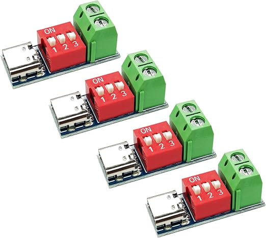
Credit: techmaster on Amazon
The 3D Print:
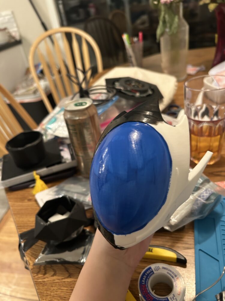
For the 3D print portion of this project, the mask itself, I purchased an stl file from Lemonite on Yeggi (seen below) and edited the text to say “All Hail Dr. Coffman” in Japanese. This didn’t end up on the final design, because I removed the base.
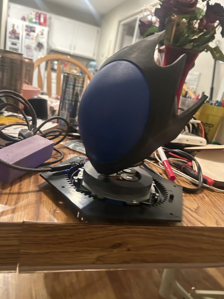
 Centering the object proved challenging. In order to keep the item suspended it needed to be balanced about its center of mass, however the side of the mask that has the face piece was heavier than the back, making it very finnicky to find the angle of best levitation. For this reason I opted not to cast the face-piece in resin as I had previously planned. The face-piece would be entirely too heavy, making the object very asymmetric about the y-axis.
Since I don’t have a multicolor printer I opted for a white print and hand painted the object from there. I sanded the print with a nail file and painted it with acrylic paint before sealing it in mod-podge. I was happy with the overall finish, I added many coats of paint because i was concerned that any stroke marks from the brush would detract from the smooth, manufactured texture of futurism.

Scheduling and Execution
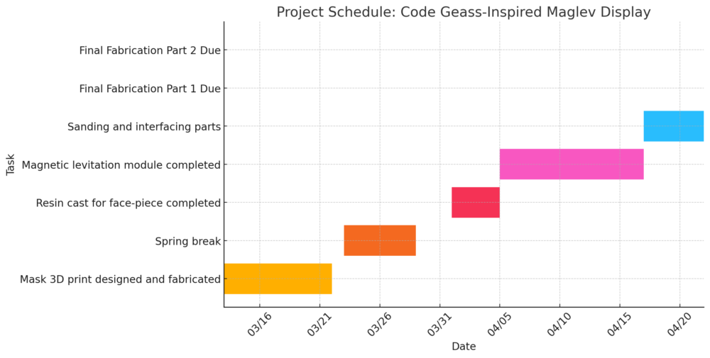
In terms of scheduling I did pretty well, the initial planned gantt chart is attached below. One place I deviated can be seen below, I planned to start 3D printing and fabrication on March 12th, to allow ample time for design refinements before March 21st. However, I ended up deciding to execute circuitry before 3D prints. This is because I knew that lead times on components would be significantly longer than editing a 3D print. I’m glad I chose this because I ended up needing to order a PD trigger module and power source. You can also see my original plan had dedicated time to resin casting, this was actually never executed because of the center of mass concern explained in detail in the product development section.
Conclusion
This Code Geass-inspired magnetic levitation display isn’t just a futuristic art piece, it’s a fusion of technology, storytelling, and interactive design. With its floating, illuminated elements, and hidden surprises, it captures the sleek, high-tech aesthetic of a world where strategy and innovation reign supreme. The use of magnetic levitation and wireless power makes it feel like something from a sci-fi anime. As a personalized tech gift, it’s the perfect way to bring a piece of that world to life for a loved one (and a giant geek). I’m really happy with how the project turned out, although I had to lose some of the frills from my dream idea (mountain-scape motifs, LEDs, and acrylic enclosures) I believe that I did a good job at prioritizing the most important components. I learn something valuable from every electronics project I make, and this was no exception. This device taught me loads about usb pd negotiations and power delivery to smart devices. It also helped me to cement some EM topics that I had only touched in a classroom setting. Overall, I’m really glad I chose this project.
Credit: ChatGPT generated gantt chart images from my given info, used to edit PD sections.
2 Comments. Leave new
What an elegant design! This is awesome, conforms to the aesthetic close to perfectly, and the implementation is perfectly executed. The 3D model came out beautiful, your integration of the THT components on the PCB looks flawless, the idea behind the project was amazing. Further, your grappling with the power management process was very refreshing to read (I have blown up one too many parts across various projects, figured I was the only one). Fantastic job, this turned out awesome.
This is a really great idea for a project, I think the maglev system is super unique way to add a dynamic element. It would be super cool to reuse this design with other helmets, a lineup of these would look really neat maybe.