
After selecting my design plans to create a nyctous acrylic tunnel book, I had about four weeks to complete the project. I planned and divided my time in those weeks as follows:
Week 1 – Test Plexiglass Laser Cutting and Shapes
Week 2 – Design and Fabricate Shapes
Week 3 – Wire and Program Lighting
Week 4 – Make Stars and Finishing Touches
I would first complete a test cut of the acrylic panels to test their overall appearance, capability for detail, most effective arrangement, and other details of the process and look. Following the test cut, I designed and fabricated the final shapes for my acrylic layers with most complications and unknowns being smoothed out by the test week. As the dynamic lights are a key part of my project, I would then dedicate a week to arranging LEDs, wiring the circuitry, programming the control, and refining the timings for an optimal rendering of the aesthetic. The final week at the end is left to make the background star panel and any other finishing touches necessary to bring the project together. This leeway was important to my schedule for any unforeseen circumstances that came up, as well as just providing time to make my result feel polished and finalized.
This test was intentionally rough and varied to gather information for a final cut while not spending overmuch time on details I may change. I gathered a lot of information from this step, and the final acrylic panes would not have come out as good without first performing this step. My concept sketch for the initial cut layout is shown below.
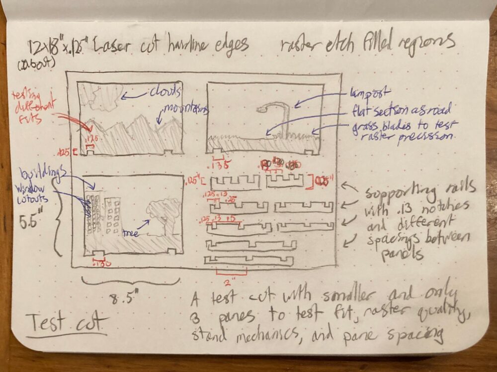 Layout sketch for the test cut
The two components to complete a cut are a raster engraving of the scene element silhouettes and a vector cut to separate the panes and associated hardware from the sheet. With the raster engraving I composed three scenes to test, described as follows in their arrangement from front to back. The first composes a lamppost over a road with blades of grass flanking either side. I primarily wanted to test the laser raster’s ability for detail in this pane, intentionally including skinny grass and lamppost features. The lamppost was also a feature I imagined putting an LED behind in my final cut, so included it here as a test for that. The second scene has two buildings with window cutouts on one side and a tree on the other, also ideas for final features being tested here. The window cutouts were especially an unknown for me, as I wanted the silhouettes to appear as buildings while not being completely unrealistic silhouettes. The third scene contains mountains and clouds, which I was most unsure of, but felt like a default background to use given my time in Colorado. In drawing the clouds I found myself including interior lines to emphasize shapes not possible with a strict silhouette, so I decided to try two different raster intensities on the clouds.
For the vector cuts, the sizing of the panes was a primary consideration, as well as the connection to the hardware holding them together. I initially considered creating an enclosure to house the acrylic panes into, but my default thinking and most approachable option to make a wood wood enclosure would likely not fit my aesthetic. Thus, I came to the idea of supporting the panes upon minimal acrylic rails and leaving it otherwise open. I would add a shroud of black paper around the panes in environments with too much light or when focusing an observer to look through the front. The lower right section of this layout contains a large variety of rails of different thicknesses and spacings between panes for testing. To connect everything together, I made mating notches in the panes and rails, with a variety of tolerances to hopefully find a proper fit.
I used CorelDraw to put this sketch into a form accepted by the laser cutters on campus, with cobbled together images for the raster.
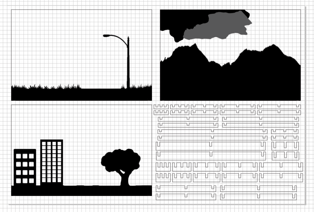
Test cut layout in CorelDraw
And then I laser cut it, where numerous problems arose, most apparent being the warp of the entire acrylic sheet.
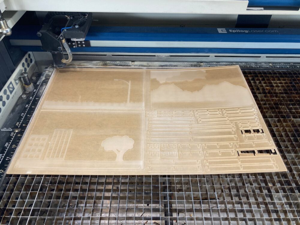
In progress test laser cut with visible warp
This is likely due to the larger regions of engraving and cutting on the right side and the protective paper still being on the acrylic. In some laser cutting processes it is more ideal to leave the protective paper on to prevent acrylic smoke from depositing onto the transparent sections of the acrylic, but I should have removed it here. The increased heat from these elements unevenly expanded the acrylic so that it warped and required several passes to cut fully through.
Another issue was the inconsistent engraving in some places, perhaps partially due to the warping. This can be most readily seen on the mountains in the above image. To further combat this, I pivoted to performing the raster engraving in multiple lower power passes on the final cut. The differing cloud intensity looked equally bad to me, being relatively even but not a good mix of translucency. Thus, all final cut patterns would be single outline silhouettes.
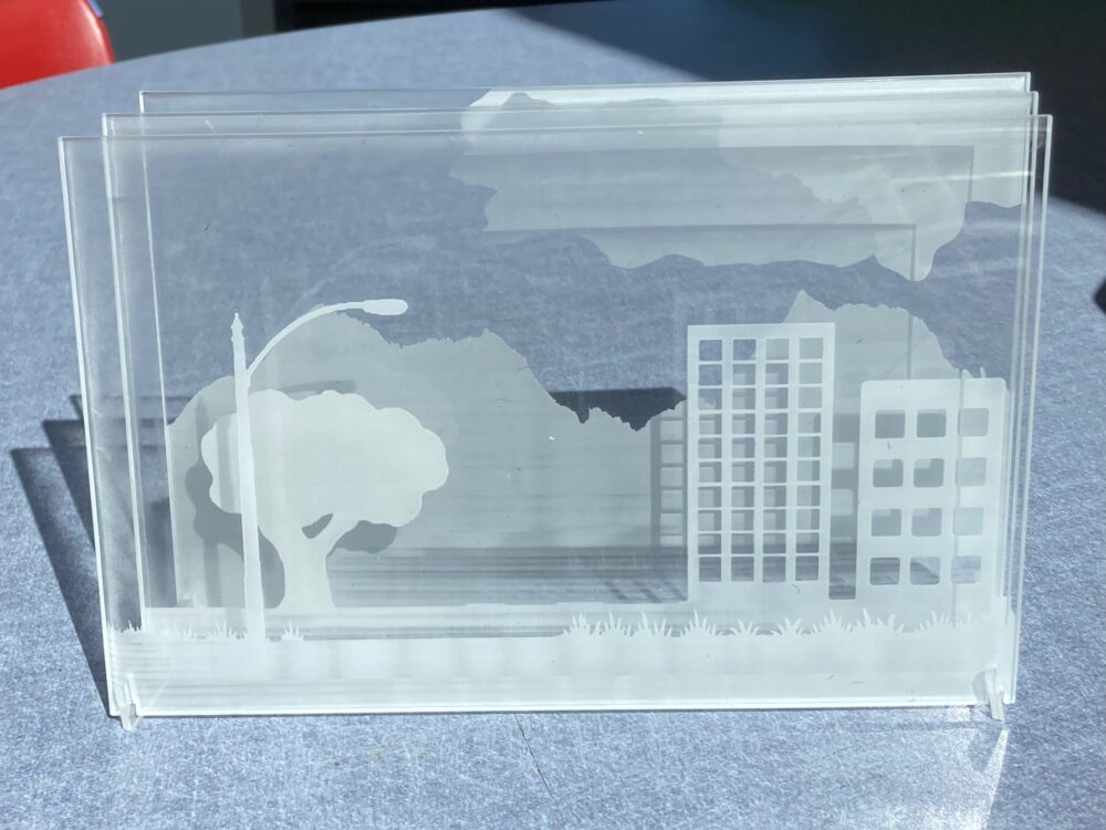
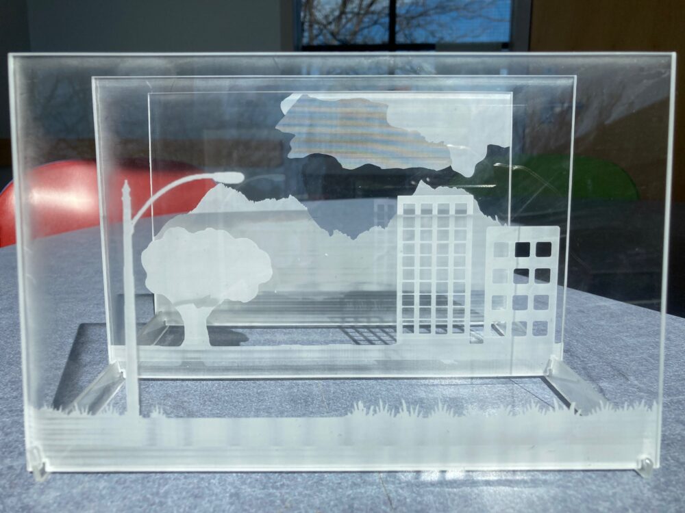
Test cut arranged both closer together and father apart
For the arrangement of the panes I found I preferred them much more in the father apart spacing, about 3 inches between panes. I also decided not to change the size of the panes. I was expecting the 5.5 inch by 8.5 inch size to feel small on the test cut, but I found instead that it worked overall and the amount of detail fit onto each pane would need to change at a larger size.
Taking all of these points into consideration, I ended up with the following design to cut my final silhouette panes.
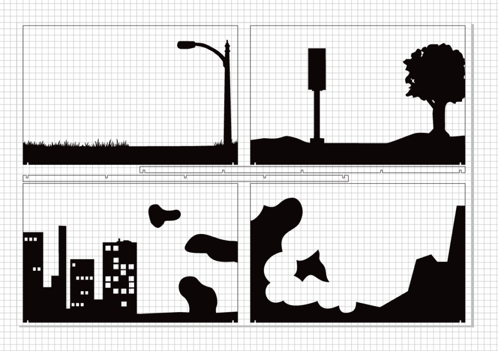
Final cut layout in CorelDraw for panels with silhouettes
One significant change I made to the designs was drawing them completely within CorelDraw instead of using externally created and collaged images. This enabled vector drawing precision without pixelated borders and a more straightforward workflow. After looking at some documentation and experimenting briefly, I also found CorelDraw to have an excellent and intuitive suite of tools for outlining these silhouettes. I spent some significant time refining the precise details and shape of every curve in these scenes, and I would happily return to CorelDraw for future projects.
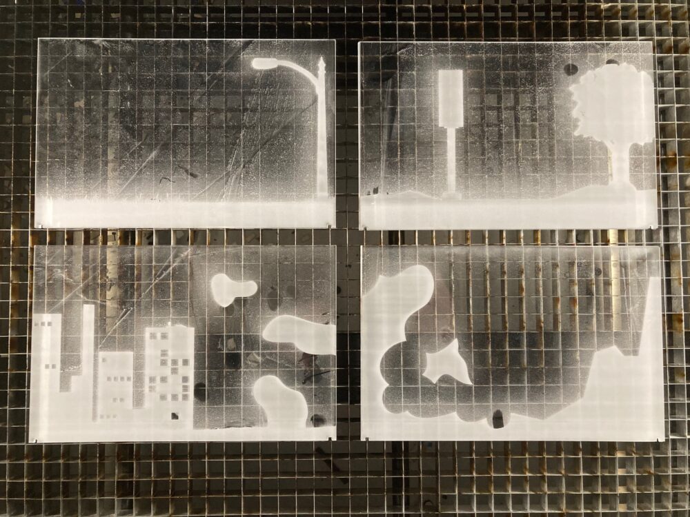
Final etched and cut panes arranged in the laser cutter bed
All things considered, I am quite happy with the result of the laser cut panes. I was able to adjust the laser cutting settings and perform multiple passes to get much better consistency on the frosted silhouettes. Some regions still have inconsistent shading, such as the sections above the ground in the top two panes, but it is solidly filled and undeniably a frosted silhouette in acrylic. I also significantly overcompensated the tolerances on the notches and spent a lot of post-processing time filing them back out to size, but that is my only other complaint with the outcome of the panes.
Even the precision on the edges of the grass came out significantly better in the final, likely due to a combination of the vector shapes and an increased dots per inch setting on the laser cutter from 500 dpi to 600 dpi.
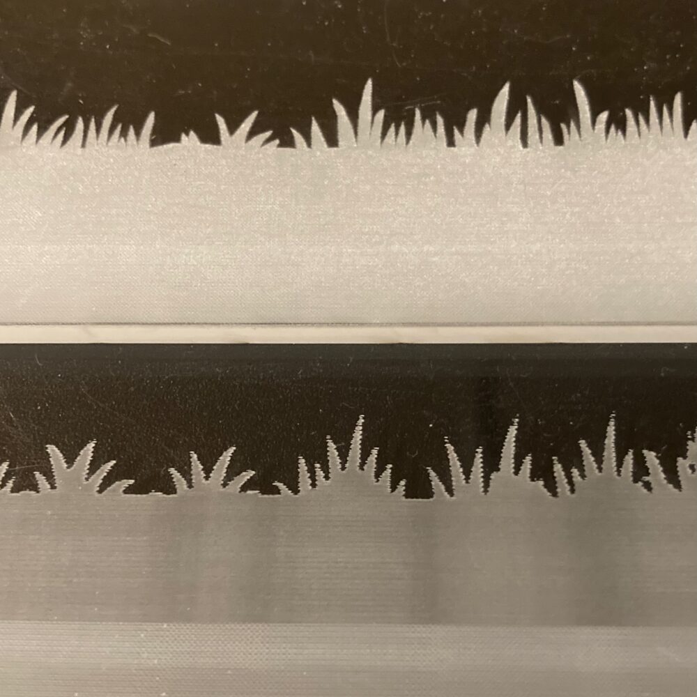
Comparison between test cut grass (bottom) and final cut grass (top)
The next step for the project was to integrate all of the dynamic LED lighting. Here are the panes assembled before lighting is added:
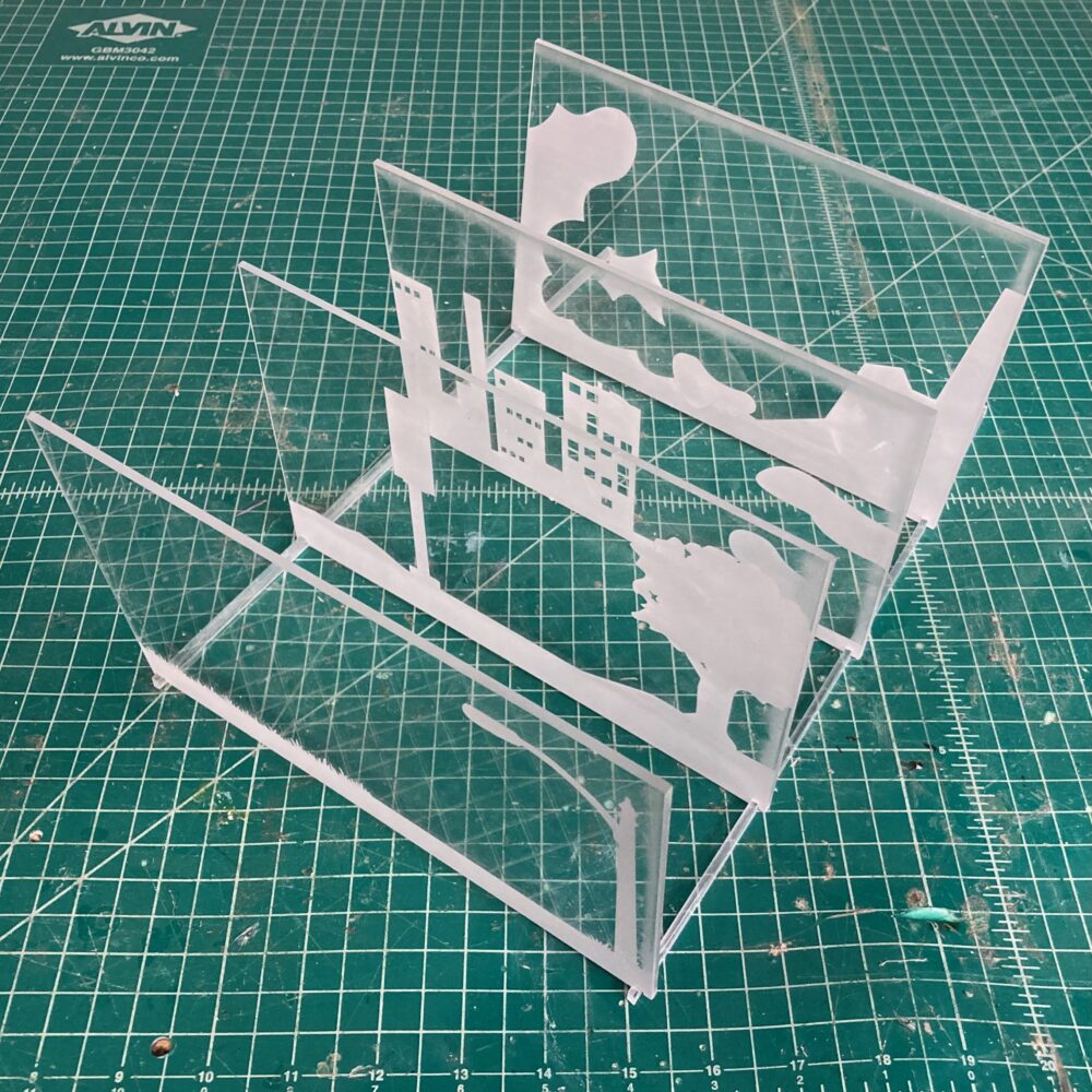
Arrangement of the final panes in sequence
The process for wiring the LEDs worked out without too many roadblocks. As planned, I used an Arduino microcontroller and breadboard that I already had on hand, and I used jumper wires with end connectors to not require soldering for more rapid iteration. In order to get varying intensity and asynchronous timing across all the LEDs in my project, I ended up using every output pin available on the Arduino board. Some pins were used for multiple LEDs when RGB LEDs did not require some color channels or when there were simply not enough channels without figuring out how to integrate multiplexers.
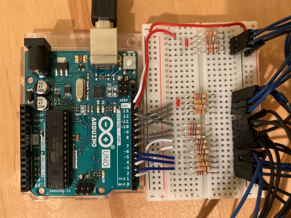
Arduino and breadboard wiring layout
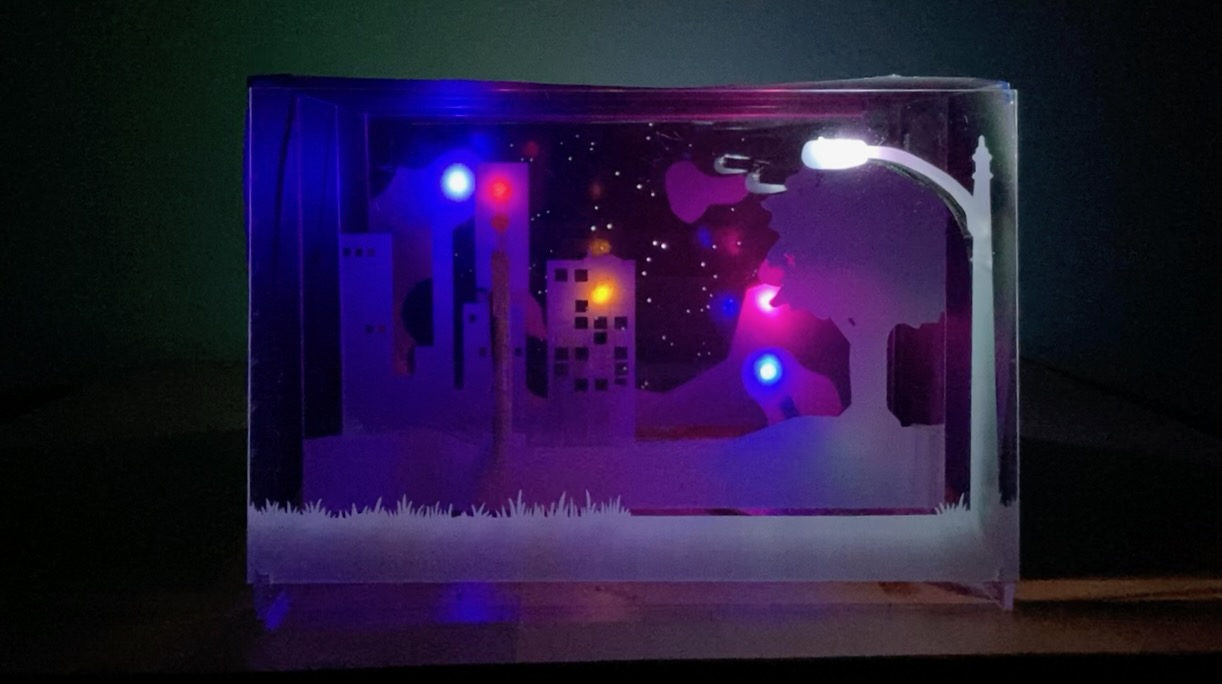
I wrote all of the LED timing code in Arduino myself, and an early test of the LEDs appeared far too synchronized, with every LED turning on or off at the exact same time as every other. My final code solves this problem with a separate timing variables for each phase of every LED’s pattern. The entire program loops through every fifth of a second, and whenever a timing variable reaches a preset threshold, it switches to the next phase of that LED’s pattern. I set the threshold values at all different prime numbers so that the LED patterns very rarely sync up. I also used RGB LEDs within my project, so those phases shift the color every cycle by set increments within that phase. The abstract shapes in the back of the tunnel book are the most apparent use of this, though the streetlamp in the foreground also shifts slowly from white to slightly yellow light and back, Try examining the patterns of the LEDs more closely in this video:
[youtube https://www.youtube.com/watch?v=FAX5lBhTpxM?feature=oembed]
The final week of this project did have to be condensed into the delayed time I had left, but I still managed to create a background of stars as shown below.

Illuminated rear pane of the tunnel book with holes in black paper acting as stars
For this final pane, I laser cut another acrylic panel with raster etching across the full surface. I then traced circles onto a rendered image of a real night sky in CorelDraw and cut that pattern into a piece of black construction paper on the laser cutter.
Overall, the manufacturing process went largely as expected. The initial test cut for panes was very helpful for finding problems before the final design, and laser cutting proved very effective in creating a variety of elements from the raster etched panes, supporting rails, and cutout of stars. Some additional insights cropped up in the aesthetics of the piece, but the manufacturing turned out exactly as I originally planned.