It has been a stressful couple of weeks. I was relieved to have gotten the bulk of my work done before spring break due to the fact that right now it is crunch time with Senior Design, Thermodynamics, and I have triathlon nationals in a little over two weeks time. Basically I just have a lot on my to-do list 🙂
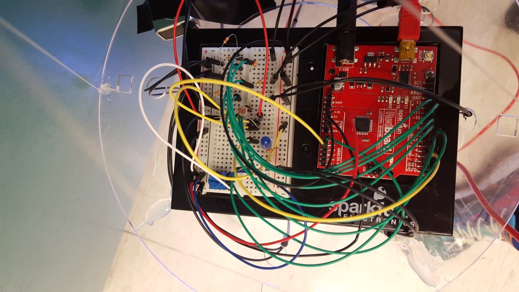
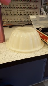
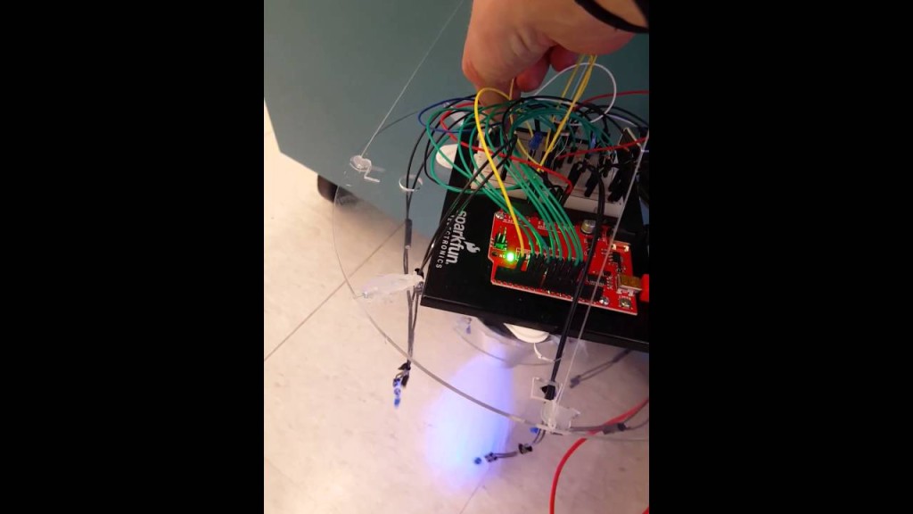
I wanted to add a more complicated component to the Arduino set-up that I had previously made. My vision was to have a bright, blue-colored LED which would light up upon the flip of the switch but then it would get brighter as the user touched the body of the jellyfish. It was a bit of a struggle trying to find a proper dome-shaped structure that could cover all of the electronic components, while looking like the main body of a jellyfish. I finally found a jello mold in GoodWill and it fit perfectly!
The main challenge these past few weeks was trying to figure out the coding for a photoresistor. It was quite simple getting the eight LED’s to light up and change flickering speed, but it was more of a challenge to code a sensor. I spent hours and hours with both Tim May and Dan Godrick, and I would like to thank them both for helping me. I became overwhelmed last night when after spending three hours on my code, the circuit still wasn’t behaving as I wanted it to. I took a step away from my project and returned to it today after much thought last night. I decided it was best to start over again (for around the seventh time!) on my code. Simplifying was the key for me to figure out what was wrong with my code. I turned to the good old SparkFun instructions booklet and went back to create the circuit for the photoresistor. I was also initially using a super bright LED but it actually didn’t work well with my set-up given it was only super bright from direct overhead view; I instead changed out the resistor to a 330 kohm resistor and a regular blue-colored LED.
When that worked, I gradually added on components. A photoresistor typically works in the way that when it gets blocked, the light turns off, but I wanted it to get brighter as the light gets blocked. What I needed to do to get it to work properly (and not as just a simple on-off sensor) was to reverse the values on the code. The light value can operate in a range between 0 and 1023, but that is the maximum range and usually the circuit can’t fill that. What I did, was I set my high value to 800 and my low value to 100. This represents the voltage that travels through the sensor when it is blocked or not. When the sensor gets blocked, the voltage increased, so the LED then gets brighter.
What is left to do is to fix the way everything is mounted on the base plate so it can all fit under the jello mold, attach extension wires to the LED and the photoresistor so they can sit higher up, and put some tissue paper on top of the jello mold to cover the electrical components.
In so far as budget, here are the following charges that have been made:
- Arduino extension wires, extra LED’s, and switch materials from Tim May $15
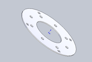
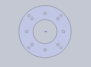
- Acrylic base $1
- FiberOptic $12
- Arduino board was rented from Dan Godrick, and all remaining materials were free from the Project Depot
- Jello Mold/electrical component cover $1
My total cost is much lower than my predicted budget, which was originally around $50