

A Timeline of the Fabrication Process:
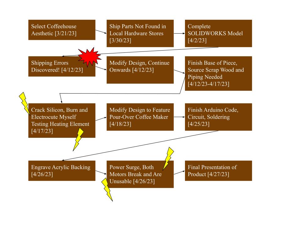
Reference this timeline as a tool to understand the fabrication process, and how the piece was made, in tandem with the text below.
The Fabrication Process
A quick recap of deciding upon my artifact’s aesthetic and design can be found within my previous post, The Fabrication of a Coffee Maker – Part 1 : What. After deciding upon an aesthetic, I began shipping parts and creating my SOLIDWORKS file for the piece simultaneously. I specifically shipped Arduino parts, acrylic for the backing, and the metallic optical table rails I needed for the piece, as these all weren’t available locally. The SOLIDWORKS file was a fairly accurate model of what I wanted to create, and it is shown below:
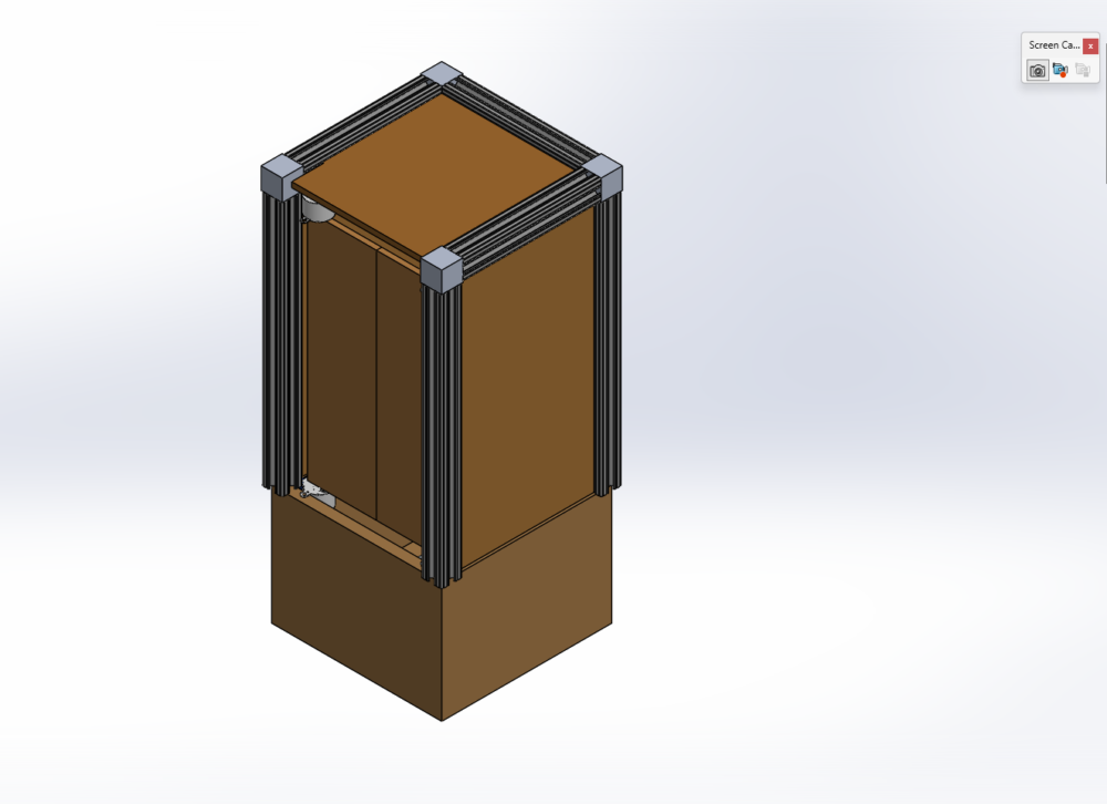
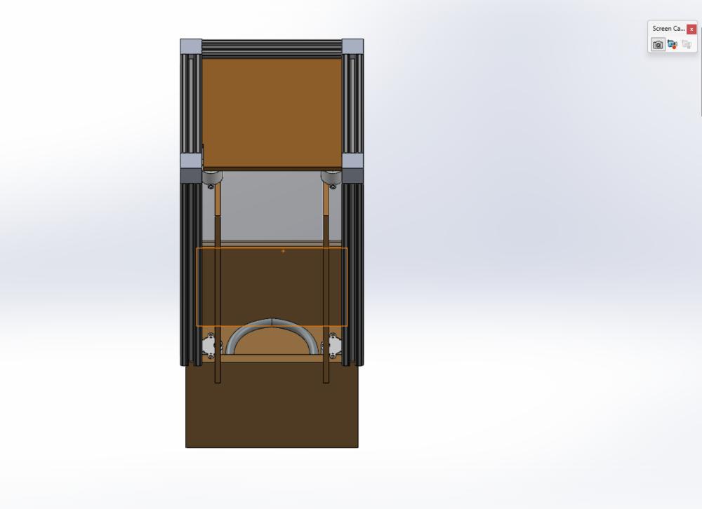
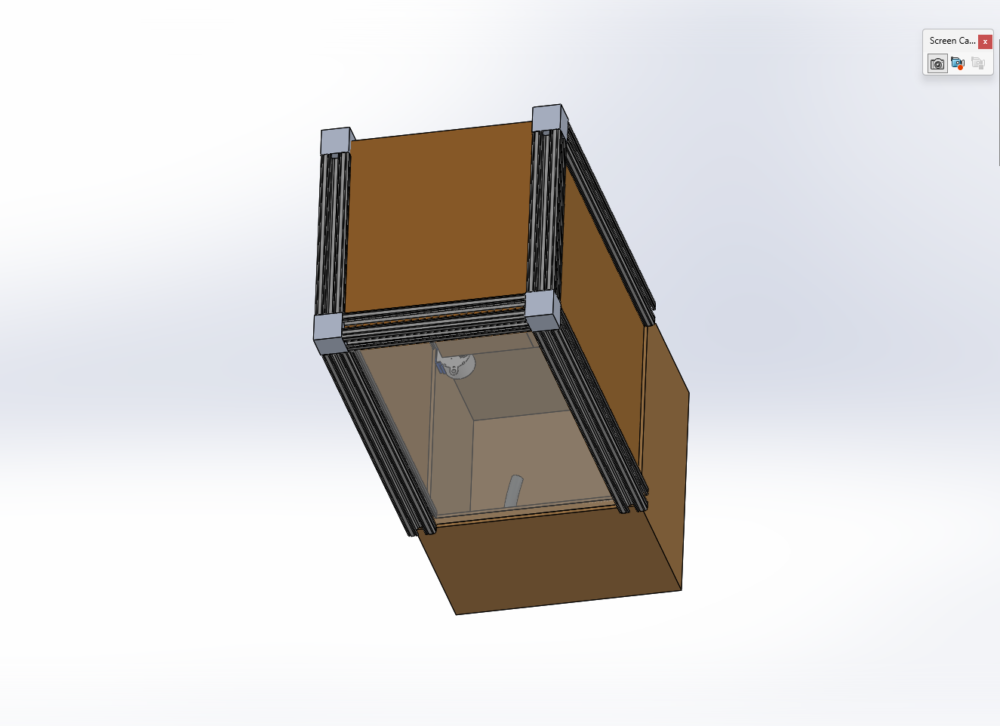
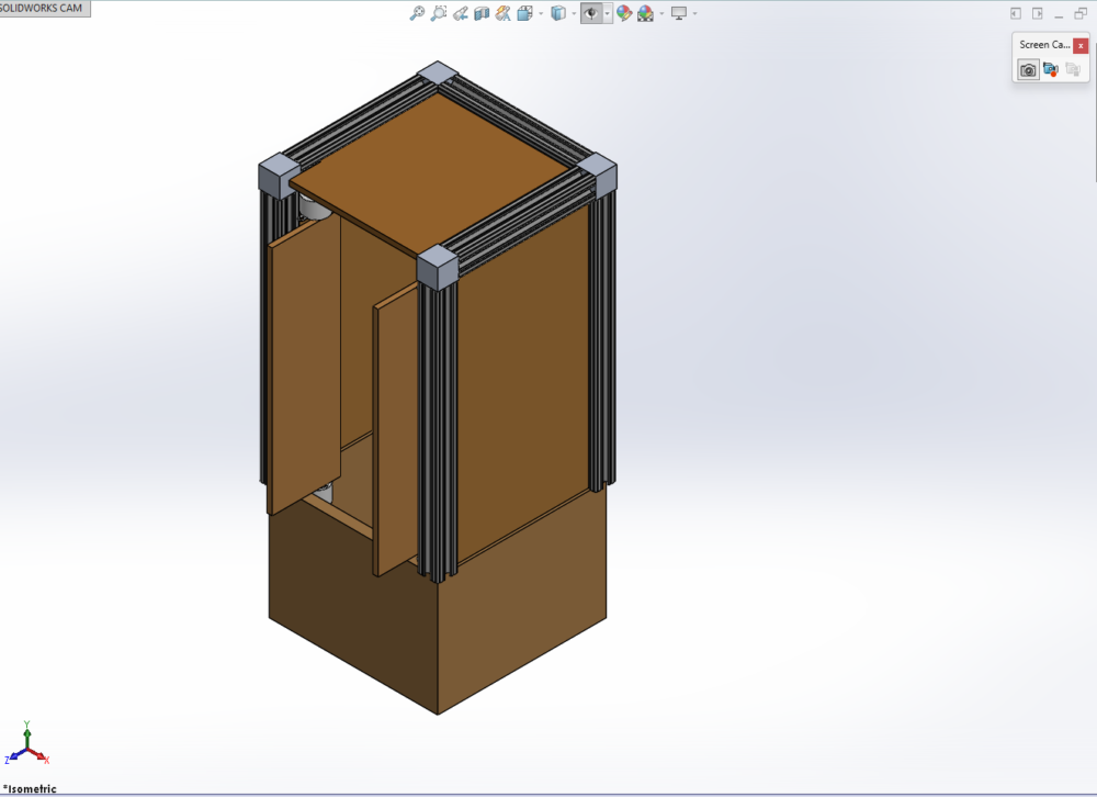
Within these screenshots, one can observe the features of the piece. The metallic edges of the piece are the optical table T-slotted rails, with an acrylic backing, and the rest of the feature being all wooden. The front doors are attached to 28byj-48 stepper motors, which are controlled by an Arduino inside (internals not pictured). The doors and the coffee maker itself would be activated with the push of a button, which would open the doors and power the heating element simultaneously.
It is following the creation of the SOLIDWORKS model that the first bumps arose. I had originally ordered a 2 packs of a of motor-driver board and motor pair, but I only received driver boards. This was the smaller of the shipping problems, as the motors had come in 4 days, and the correct pieces would arrive with a good chunk of time left for fabrication. The second shipping problem was much more egregious however, and occurred when I had shipped the metallic rails I needed. I thought that I had ordered 12 1′ rails for the piece, however, when I opened the package, I only had 1 12″ rail. Given that my design required a minimum of 6 of these 1′ rails, and shipping had taken about a week and a half, and I only had a week and a half left to work on the part; I had to redesign with what I had. The final design consisted of an entirely wooden design, whilst keeping the acrylic backing. A hiccup for sure, but no major harm was done to the piece’s aesthetic or function.
Following these small issues, my roommate actually helped to create the base of the piece out of MDF, as it was free at his work. It was during this time that I gathered piping for the piece at Home Depot, and began assembly of the fluid system within the piece. The fluid system consisted of a melange of brass, silicon, and anodized steel pieces, as well as a heating element salvaged from my already-broken coffee maker. The design of the piping system took a good chunk of time and almost all of the funding I had, but I eventually had a prototype ready for testing. It can be seen pictured below:
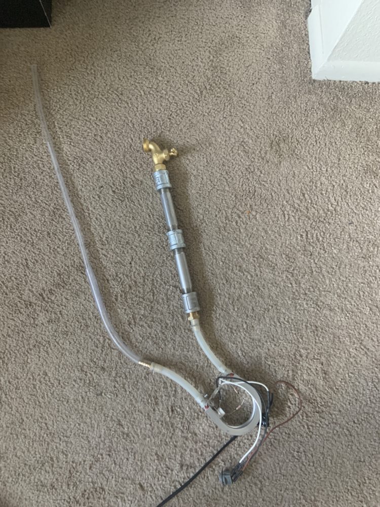
The design takes in water from a reservoir using the plastic tubing on the lest, feeds that into the silicon tube attached to the heating element, and out the other, shorter side. The shorter side consists of silicon, stainless steel, and a brass faucet. The faucet was intended to work as a valve, regulating flow of the boiling liquid, ensuring that it all didn’t spout out at once, and overfill the chamber where the grounds were to be held.
I was quite proud of the design, and all that was left was testing the piece before I placed it inside the housing unit. This is where the second and most disastrous of problems hit the project. I was testing the assembly in my bathroom, running cool water through the inlet, and watching the boiling water come out of the outlet. Thus far, back flow had not occurred; which would prove disastrous for the machine. A back flow would have water boiling in both the outlet and inlet, and would lead to a catastrophic failure, as steam would be pushed through the heating element, leading to extremely dangerous superheated vapor pouring out of the brass exit.
As this was to be avoided at all costs, I was understandably extremely frightened when a back flow did suddenly occur. Boiling water and steam began spewing out of both the inlet and outlet, rendering the previously cold pieces hot and nearly untouchable. Nervous, and with burns already forming on my fingertips, I let go of the inlet, and went to switch off the power supply to the heating element. In my hurry, I hadn’t noticed the water coating the wires of the piece, and, unsurprisingly, electrocuted myself. What’s worse is that I had somehow managed to crack the expensive heat-resistant silicon tubing, and the piece was now broken and more dangerous.
It was following this fiasco that I made yet another modification to the design. With 10 days until the projects arrival, and most of my budget lost, I decided to purchase a small pour-over coffee maker, which would be presented to the user after the doors swung open; still controlled by the Arduino.
It took quite some time, but I managed to cut and paint the remaining wooden panels, code the stepper motors, affix them to my piece, and engrave the acrylic backing with the ITLL’s laser cutter. By then, it was April 26th, the assembly was completed, and all I had to finish was adding more glue to secure the Arduino’s button to the wooden hole I had cut, and some final touch-ups with the paint. I was working on this diligently and late into the night when disaster struck yet again.
Whilst working in my Uncle’s garage, with rain pouring outside, I foolishly decided to run the miter-saw with my Arduino plugged in. Thunder shook the garage right as I turned on the saw, and suddenly, all the power to the garage was out. In the dark, I frantically reset the breaker, but the damage had been done. The motors refused to work, and upon checking with my ammeter, there was no current running. The motors were dead the night before my presentation; the final nail in the coffin for the coffee maker.
Ultimately, I presented a piece that resembled my original idea, and while it did match the coffeehouse aesthetic, it had none of the functionality I had intended the piece to have. Despite this, I feel as though I had learned an incredible amount, as the best learning is done through failing.
Concluding the Project
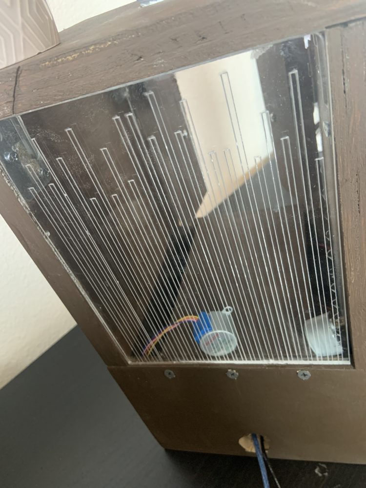
This whole project was lesson in overcoming adversity, and learning how to mitigate problems that may arise. I felt as though I had successfully matched the aesthetic of the coffeehouse; as my piece still featured the soothing earthen tones of the Havana Coffee paint I selected from Home Depot, and the splash of green from the succulent on top. With the abstract engraving on the backing, and the stainless steel hinges and central funnel, a sense of a modernity is added to the piece.
Ultimately, I feel as though the aesthetic is communicated quite nicely, and I learned the importance of crisis mitigation, overcoming pitfalls, and knowing one’s abilities, as I may have bitten off more than I could chew.
Below are photos of the final piece:
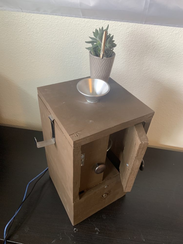

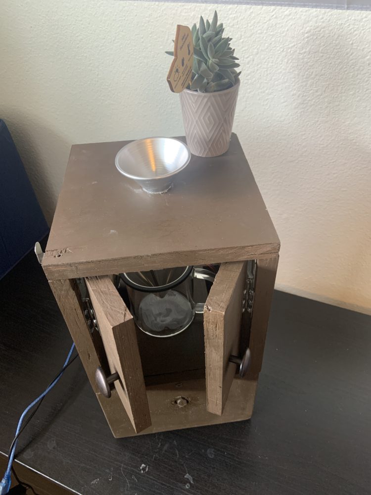
This finished product will likely remain as a housing for my pour-over coffee maker, and will be be redone over the summer, fixing the motor issue, and being remade with wood that one can stain.
Below is a video of my final presentation:
1 Comment. Leave new
Wow, what an incredible journey! Despite various challenges, it’s remarkable how you stuck to your idea and created a practical coffee machine. Excellent job!