
While this project had some significant changes due to COVID-19, I still feel that I ended up with a good final result. While I was originally going to build a speaker enclosure in the woodshop, I ended up having to make a render and detailed construction plans instead. In this post I cover what my final project ended up being, how I did it and details of the final product and the process to get there. For a description of the origins of the project, the underlying aesthetics and what I will do next, please refer to the next post titled Speaker Enclosure: Main Project Part 2.
The main feature of this project is the renders which will show off the design that I have created. My work has been in Solidworks Visualize, where I have spent several weeks learning this rendering software. Not only is learning a rendering software a useful way for me to display my design in context, it is also a valuable skill for me to have as an engineer going out into my career. While I knew that there was going to be a significant learning curve with a new software, I did not expect how difficult it was going to be to produce photo realistic renders. In part it could be that my expectations are too high, but I have spent nearly a month tinkering with settings, appearances, scenes and lighting. While I am pretty strapped for time, it is almost beneficial that each render attempt takes around 3 hours, because it forces me to always be trying new changes and doing work in between. Below is a selection of some of my renders for this project. I am going to keep working on these until the final showcase, so they may be changing occasionally until then.

Figure 1: Brick wall backdrop
While this one came out better than previous renders, I still have some work to do on the lighting. I think that my issues are twofold: the lighting should be coming from the upper right side rather than the bottom left on the speaker, second the wall is far too light to try and match in terms of lighting. I could fix the second issue by putting the backdrop image into LightRoom and reducing the exposure and saturation. Hopefully time will allow for these changes before the showcase. One thing that I am happy with about this render in Figure 1 is how well the shadows and reflections are coming out.

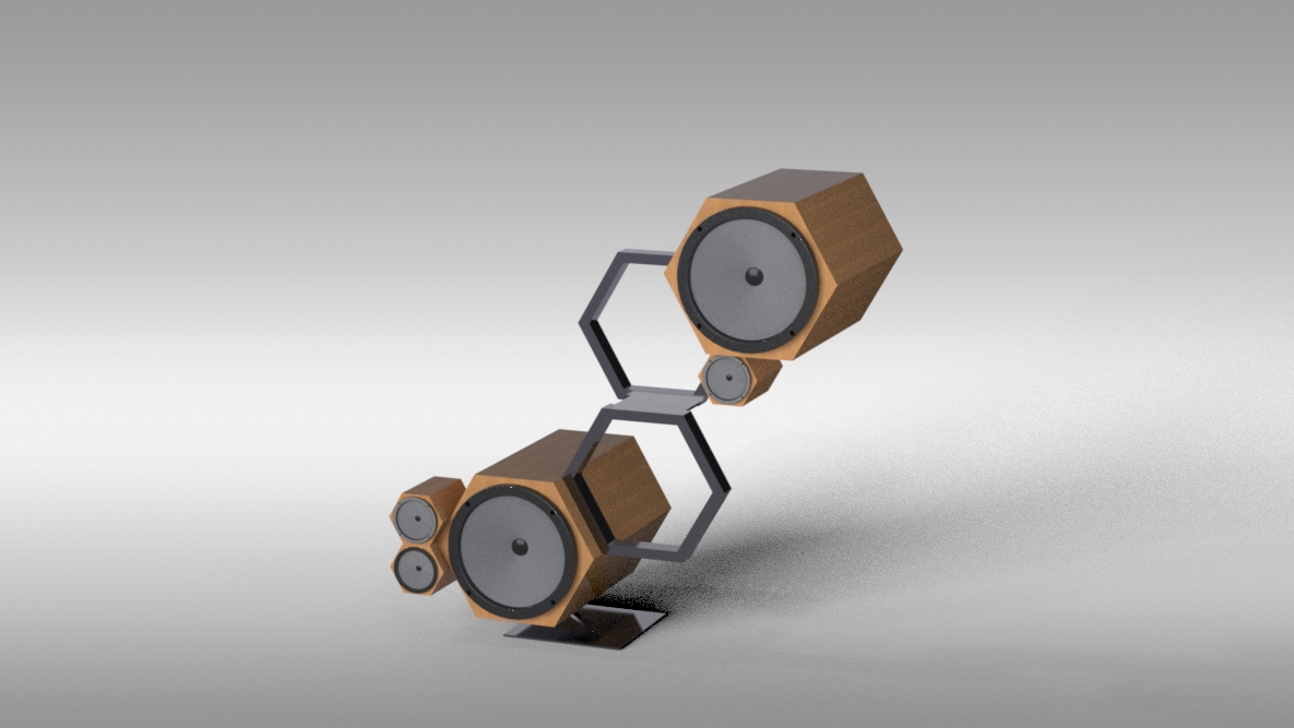
Figure 2: Studio view
As much as I want to be able to use an interesting backdrop, studio lighting is way easier to work with. This render is much older than the brick backdrop one and it seems just as if not more developed. Here I played with the focal length of my camera to get a stronger perspective view on the speaker stand.

Figure 3: Alternate studio view
This is a slightly shifted perspective. I’ve found that fast renders produce grainy images, like you can see in some of the details of this render. Although the image size was large, having a small number of passes results in strange textures and grain. It has been really interesting learning a rendering software as complex as this is. If I had not had this project to work on, there is absolutely no way that I would have been able to get this much practice. I’m hoping to keep working on this project and start rendering some of my other projects as well.
Now this project was not just rendering work to start, it was originally a whole design build process, which meant procuring materials and setting up construction documentation. In figure 4 below the purchased speaker components and the bill of materials are shown. The only components not purchased from the bill of materials is the steel tube, because that was added after the project changed direction.


Figure 4: Purchased speaker components (left) and bill of materials (right)
Because I have most of the parts for this project and I like the design, I would actually like to build it some day. As a result, it is imperative to have an accurate set of construction documents especially when the aesthetics require that things be well built. The potential construction of the project will be broken down into 4 phases. The first phase is rough cutting and routing the wood. See figure 5 below for an example of the part drawing set and a screenshot of a DXF file used for laser cutting.


Figure 5: Part drawing example (left) and laser cutter pattern (right)
To get everything as accurate as possible, after the wood is rough cut, patterns will be laser cut out of thinner plywood or MDF. These patterns can then be used with a pattern bit on a router to create multiple identical parts out of thicker pieces of wood. In figure 5, a part drawing and the corresponding pattern are shown for the front plate of the larger drums. All of these parts have been designed to avoid sharp interior turns to allow for easy router replication.
The second phase is welding together the base plate and the hexagonal supports from steel stock. While these are simple welding operations, I am without a welding machine, so having shop access will be imperative. The hexagons are to be made from hollow rectangular steel tube. The use of tube is advantageous because it is less expensive and more rigid than bar stock and it will allow me to pass wires from the amplifier in the bottom drum up to the speaker in the top drum. The bottom plate is made from three parts: an upper plate that bolts into the bottom wooden drum, an angled riser made from the same rectangular tube as is used in the hexagons, and a large steel base plate.
The third phase is finishing of the separate components. For the wood, a dark natural stain is preferred, and for the steel, a high gloss black paint would be perfect. These are the colors and textures used in my renderings, and I feel that they make the project look much more interesting than plain pine. The fourth phase is the wiring and speaker installation. The only important thing is that the power supply and amplifier both need to go in the bottom drum in order to balance the project out. Even without those components, the centroid is not past the edge of the plate, but it would be far likelier to tip over. The wires for the top drum will need to be routed by running a cable through the hexagons during welding and then pulling the wire through before the finishing/ painting. It will be a difficult assembly and construction process, but the end result could be a really interesting speaker.
Because my degree will be done by the end of summer, and my easy woodshop access will likely go with it, it is difficult to determine when or if this project will be built in person. I am hopeful that facilities will open up before my chance goes away, but I must be realistic. I think that it is a testament to an interesting design that even though I don’t have to build this project any more, I still want to. I am extremely glad that I switched my designs around, because I find this one much more interesting to work with.
1 Comment. Leave new
I think your new design is so much better than your very first one. This adds so much more depth to your project and you can try out so many creative angles. Even though it’s not a physical model, I think having to take this route is going to make a speaker you’ll be so much prouder of. Your renderings are beautiful and since you have all the materials and drawings, hopefully you can actually own this one day!