
Link to Final Presentation: https://youtu.be/w53H1B6TMHI
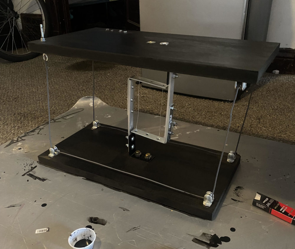
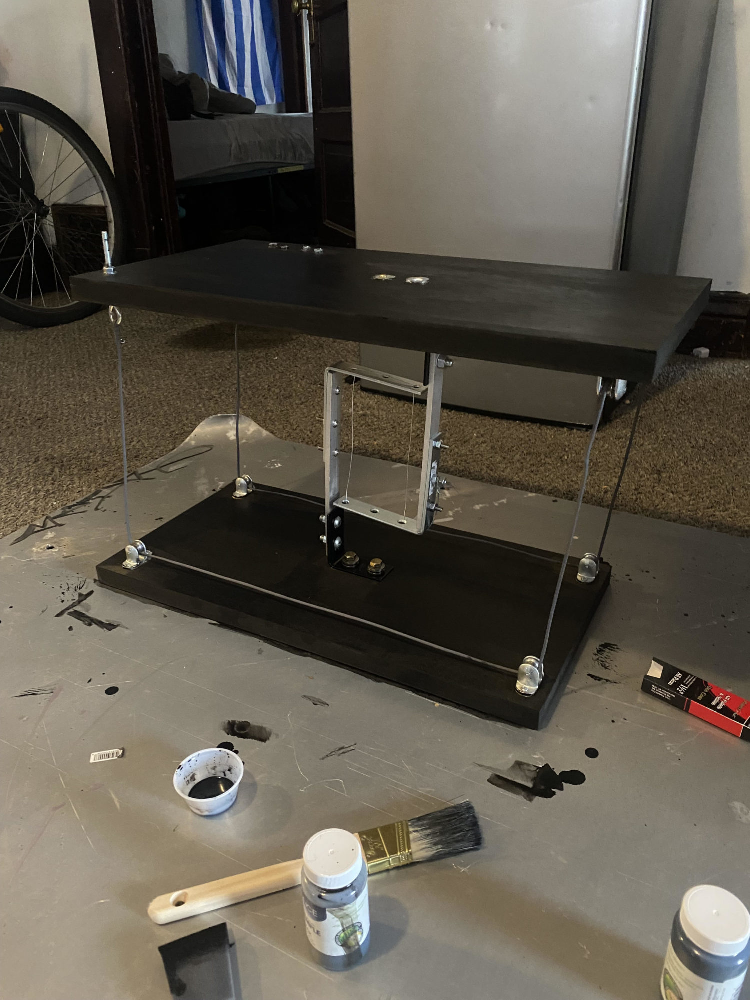
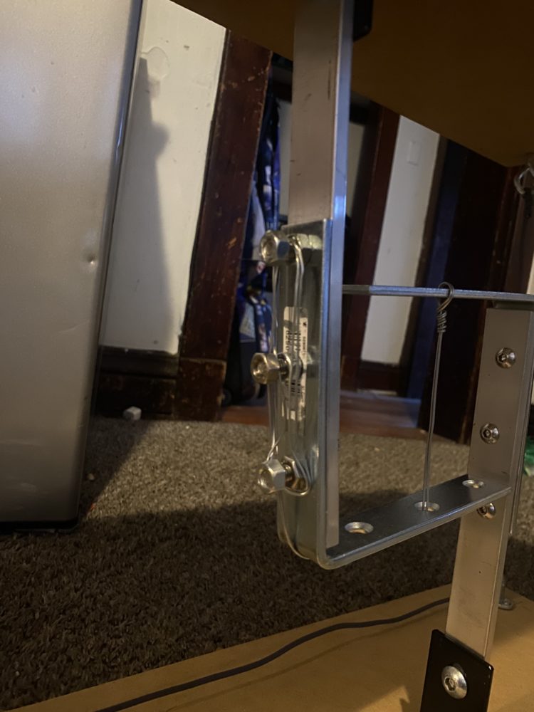
The above tensegrity table utilizes two cables, one that utilizes a pully system to stabilize the outer corners of the table, and one in the center that physically holds the entire weight of the top surface. The center wire is composed of two 20 lb steel wires that can hold up to 30 pounds on top of the table. The outer wire uses a single steel wire threaded through paracord to achieve an optimal strength and rigidity in order to stabilize the above surface.
As you can see above, the table is at two different heights in the photo with the left being about 3 ft tall and the right photo about 2.5 ft tall. The table works great and holds its own weight well with the exception of a little bit of bending in the center beams. I made a subtle change to the center to lessen the bending which you can see in the final design at the bottom. I also plan on trying to redesign this center at a later point to perhaps include steel beams that are welded together to create those right angles. I didn’t do this in my first design as I don’t currently have welding experience and it is also much more tough to machine holes in steel than aluminum.
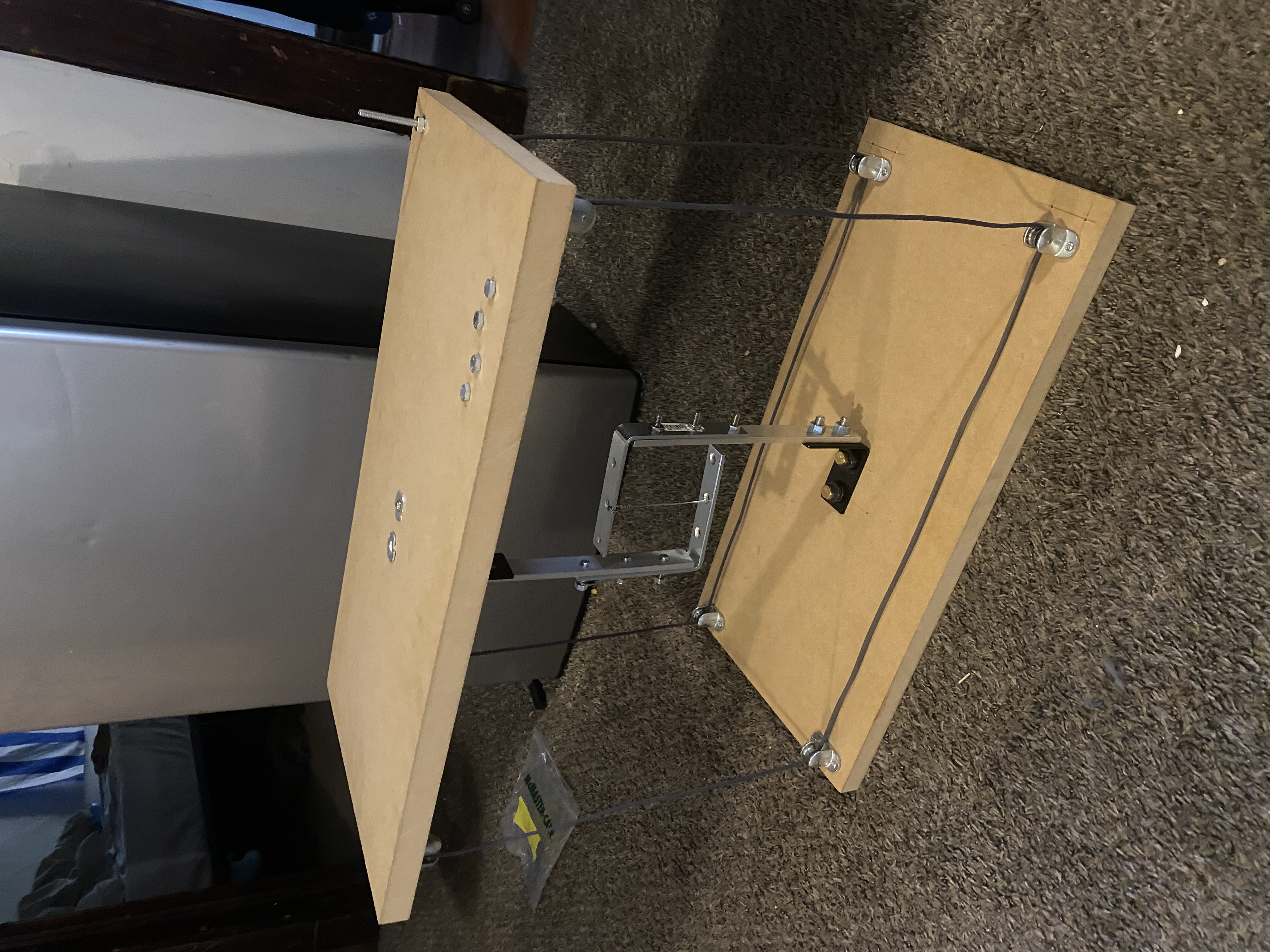
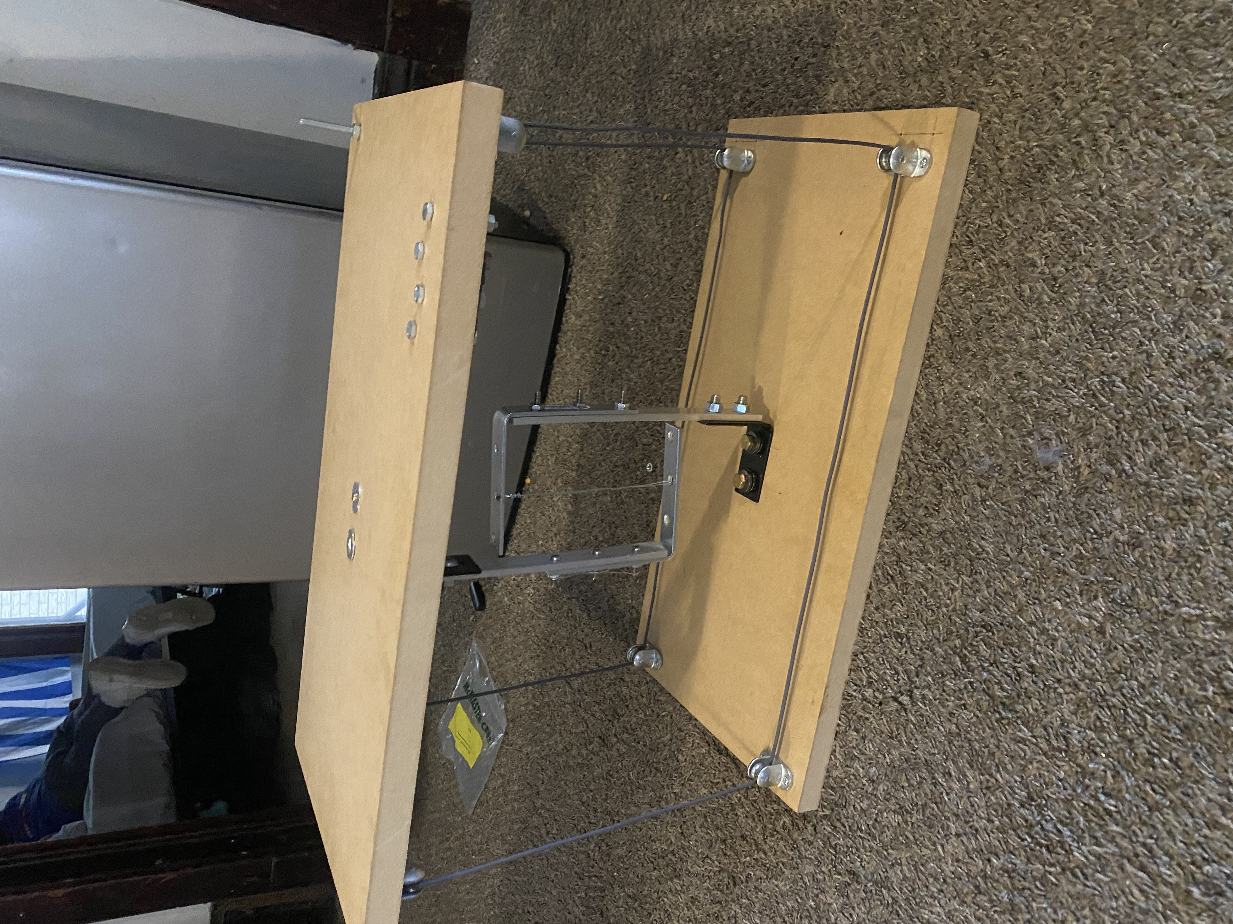
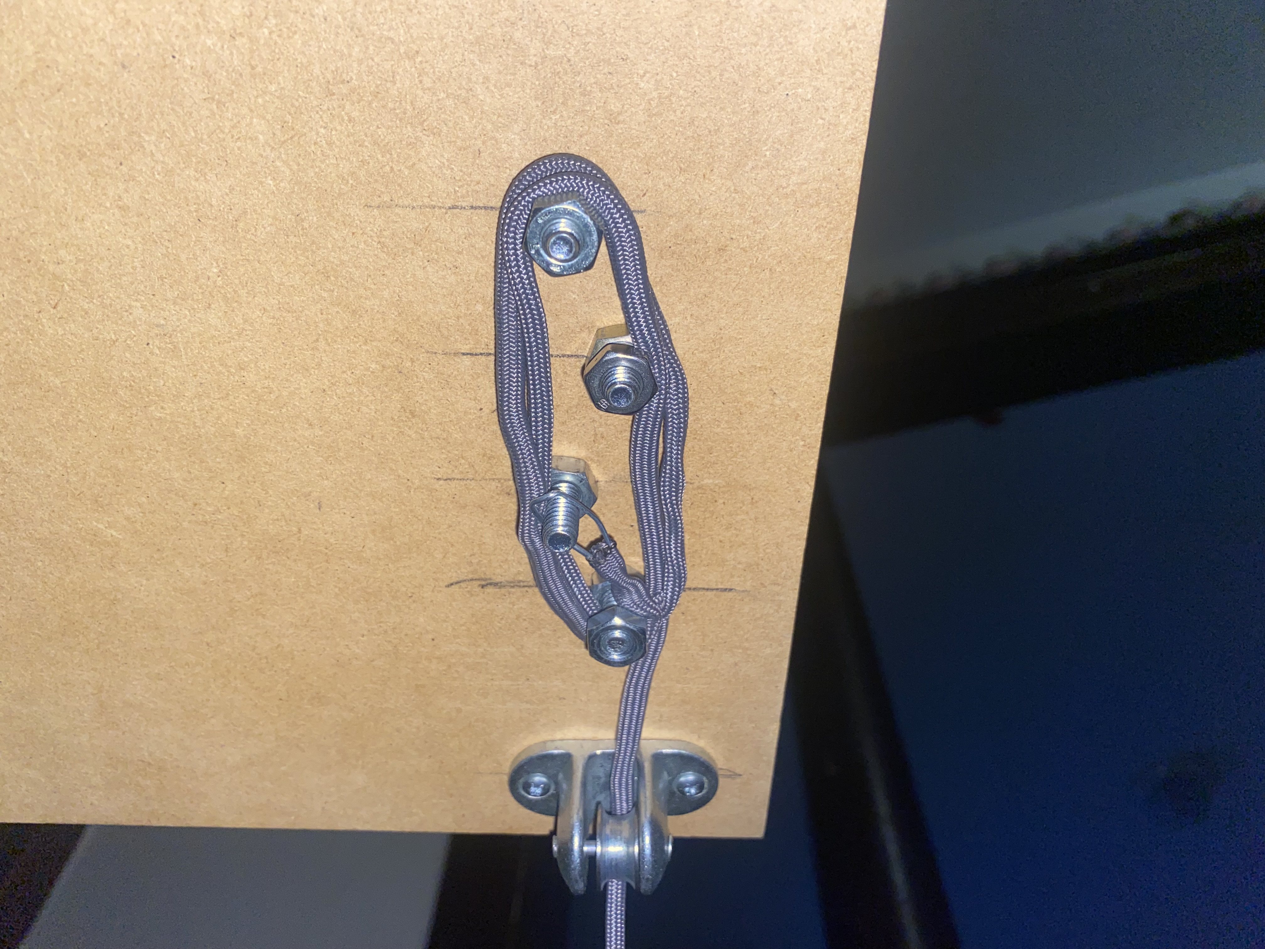
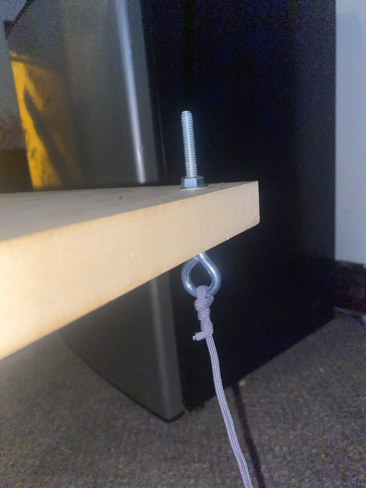
Below are some photos showing the close-up visuals of the attachment mechanisms for the wires and how it actually adjusts its height. The photos below show how the slack in the extra wire is maintained and held taught. The extra wire is wrapped around several bolts and then looped around one of them where it can be secured with a nut. This is best shown on the photo on the right, the nut is removed to show the looped wire. The paracord seen below just provides housing for a metal wire I threaded through it. I did this to maintain a rigid and non-stretchable cord as well as to have a nicer cleaner look than the wire itself. Also, the reason I staggered these bolts in a non-linear fashion is to add more paths for looping the wire to get more precision.
The photo below shows how additional tension is introduced to the outer wire. The eye bolt has about 2 inches of threading. Once the outer wire is tightened as much as it can be by hand and secured like the photos below, the eyebolt is screwed into the nut above the table introducing the extra tension. This adds enough to make the table very sturdy and not wobble much at all.
Overall the table attained the strength and sturdiness that I had hoped which I was very happy about. It is able to hold weight throughout the top surface without tipping due to the pulley system which could theoretically distribute to tip over if too much weight if applied on one side or the other, but due to the steel wire within the paracord it holds its form well and resists shifting around the pulley and other radii throughout the system.
2 Comments. Leave new
what’s good slime, this bussin bussin frfr
Hi Ben, I’m really glad that your project turned out great! I remember seeing it when you were in the initial stages of designing and building it and thought of how cool of an idea it was. I really enjoy the photos you shared, as it highlights all of the features of the product. The mechanism you implemented to have the height adjustable is really cool. Overall good job!