
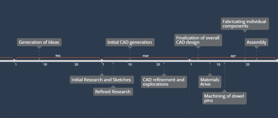
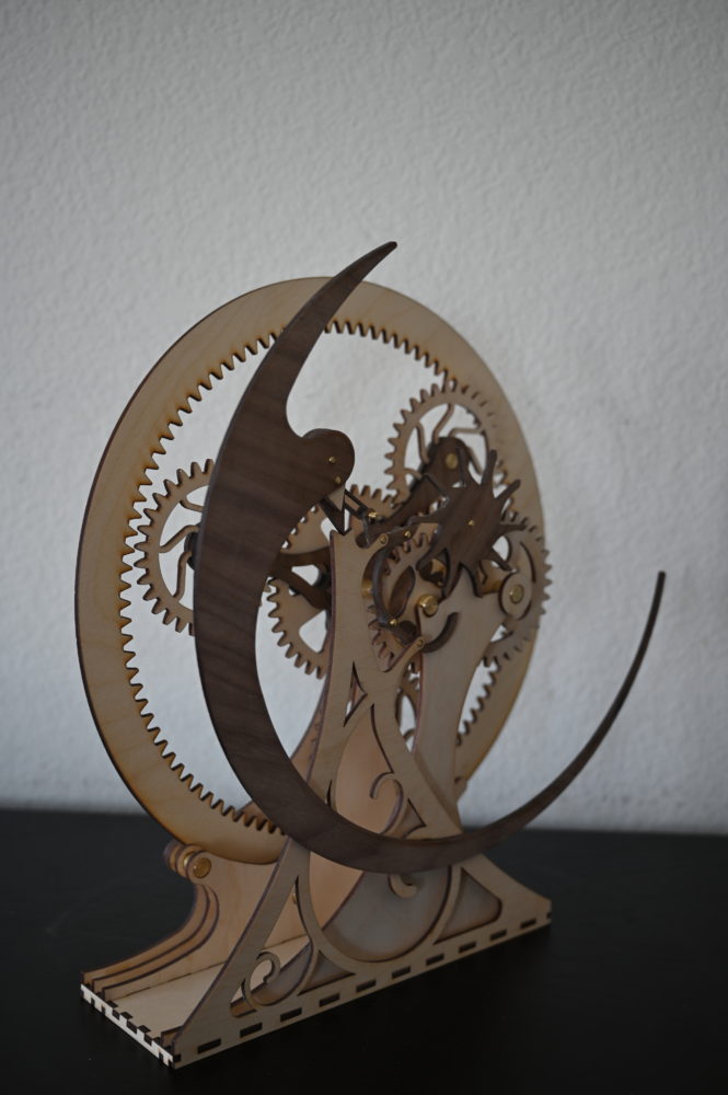
As a brief re-introduction to my project, I designed and fabricated a wooden escapement mechanism to act primarily as an art piece for my apartment. I wanted to mimic the aesthetics that are present in antique clocks and wooden kinetic sculptures. This means that I focused on complex geared systems, using different woods to differentiate different parts of the mechanism, and using brass as connecting elements. The wooden escapement that I designed has been fully realized, though it requires a few minor adjustments which can be easily fabricated. This post on the wooden escapement I created will focus more on the fabrication, more information on the aesthetics of the artifact can be found in my first post here. While the artifact isn’t as functional as I would like currently, there are a few minor modifications that can be made which will greatly increase the functionality while maintaining the aesthetic that I have chosen. Before I get into the fabrication process more, I have a brief timeline graphic which outlines when certain project milestones occurred. This began with generation of initial ideas, research, and sketches.
Initial Research and Sketches
Much of this phase of the project was dominated by google searches. I wanted to find different inspirations for the design of my project. From this point, I drew inspiration from a variety of different antique clock designs, Derek Hugger, and Dolf Perenti. The latter two designers focus more on wooden kinetic sculptures. I was particularly drawn to their use of different types of wood to draw contrast and attention to different elements within a piece. I also began working on hand sketching different ideas at this time, as well as running simple calculations to determine the rough size and shape of the device, as well as the kinds of gearing systems that I was interested in. I also used this time to brush up on how to design and integrate gears in SolidWorks as well as using physical collision motion so that I would be able to verify my design.
CAD Generation
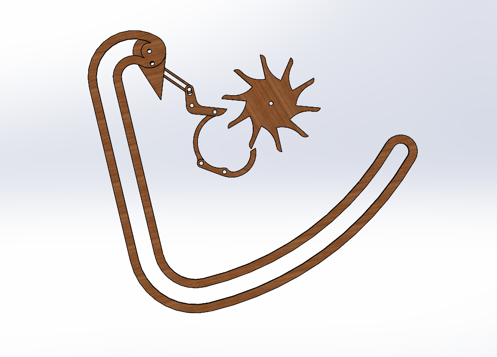
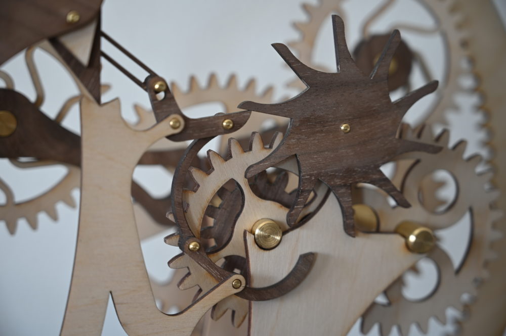
I have previously documented this phase of my design the most. I began by creating the escapement mechanism since this was the focus of my project. I heavily drew inspiration from Organic Escapement #4 by Dolf Perenti on YouTube, but I did make some modifications to the mechanism and pendulum design. During this period, I focused mainly on creating the kind of motion I wanted to emulate. I went through several iterations of the gear and escapement arms before arriving at the design pictured in the image on the left. This was able to successfully create the motion that I was the most interested in, while also doing it in a very visually appealing way. The movement of the arms and pendulum relative to the gear really captured what I was targeting with the antique clock aesthetic inspiration.
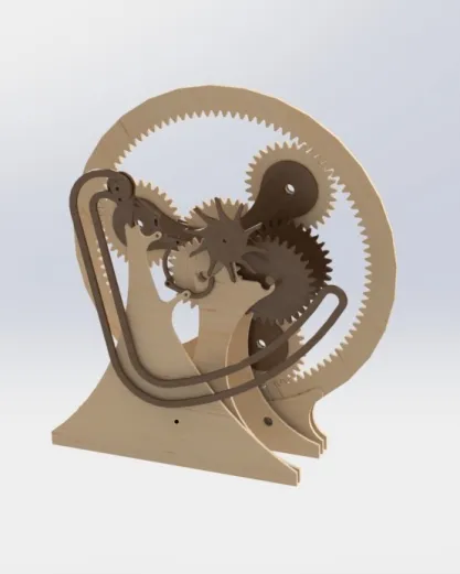
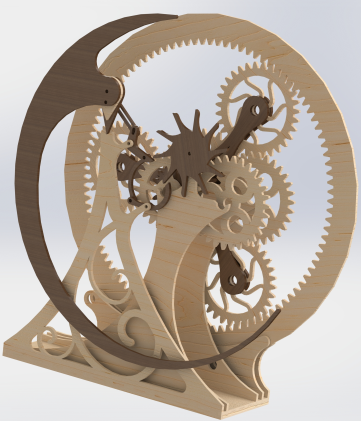
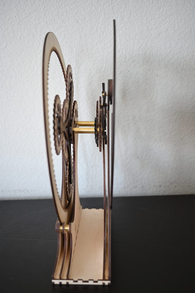
From this point, I worked on building out the design around the escapement mechanism. Since I wanted to create a celebration of gears, I decided to include a large planetary gear system to frame the entire project. To achieve the rate of motion that I wanted, I ended up adding secondary gearing systems to both the escapement and the planetary gear system. This was done to slow the conversion of potential energy to kinetic energy. This led me to the CAD design in the middle image above. While I was happy with the overall layout, I didn’t like the aesthetics. This didn’t match the clean aesthetics that I was targeting and overall looked very blocky. So, I engaged in massive redesigns for many of the parts. I added a central motif to the front panel to help keep with the organic theme of the aesthetic, I added embellishments to many of the gears of the project, and I redesigned the pendulum. I wanted to use the pendulum to help tie the front escapement mechanism to the large planetary gear system. I did this by following the curvature of the ring gear with the pendulum. At this point, I arrived at the design on the right, which I used to fabricate each component.
Physical Manufacturing
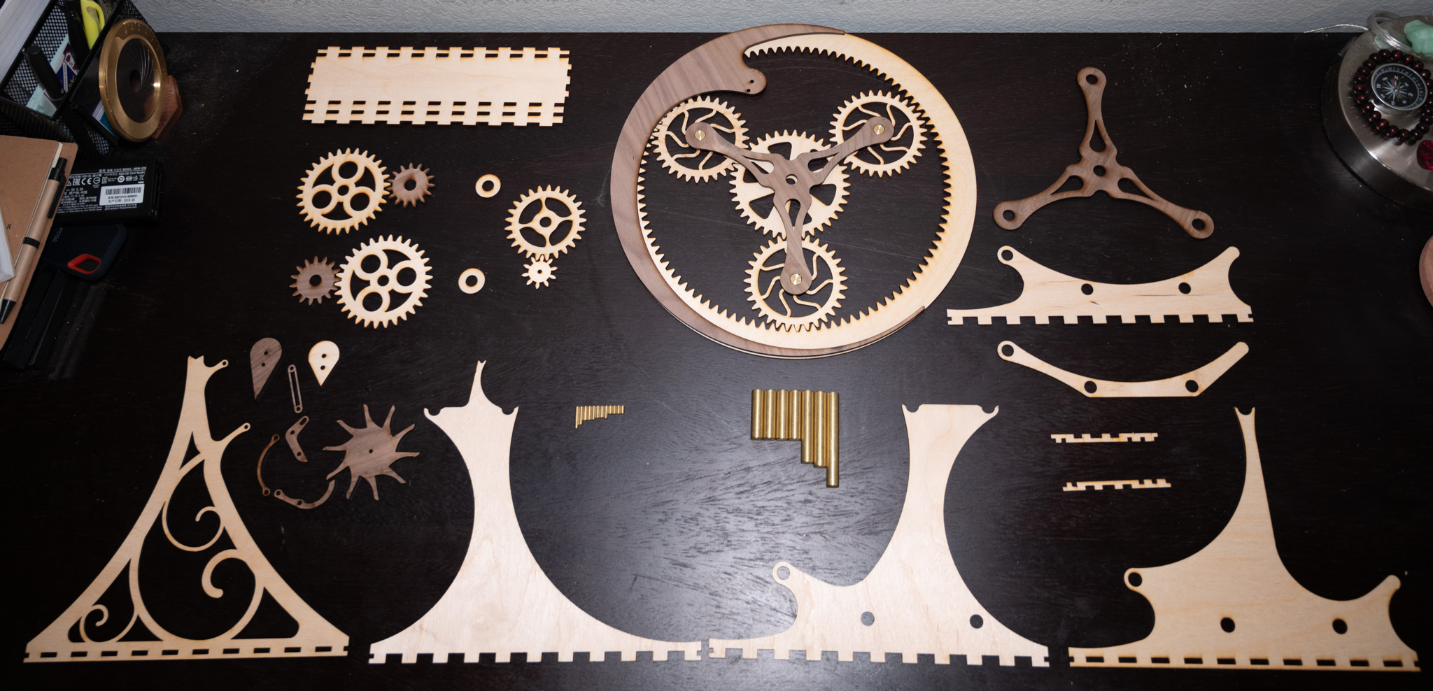
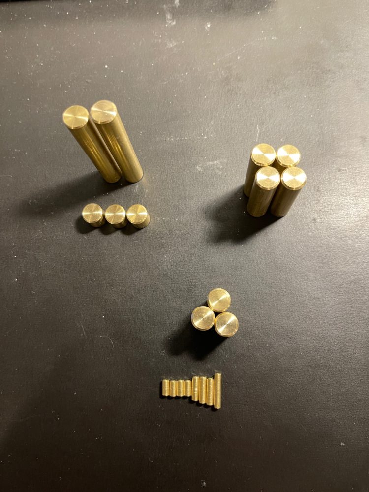 The beginning of this phase of the project started with collecting materials. I was able to source the wood for the project from craftcloset.com, which offers a wide variety of laser-cutter ready plywood. The brass I was able to source locally as both 1/8″ and 3/8″ rod. I bought extra of all the above materials to ensure that I would be able to fix any potential problems that arose. I began the physical construction process by fabricating the brass dowels that would hold the project together and provide axles for the variety of gear systems. This was made in two separate steps, a roughing step and a finishing step. The roughing step was done using a bandsaw, where the correct lengths were marked out by hand and extra room was added to ensure enough material could be removed during the finishing step. This left a rough edge and could have resulted in uneven cuts depending on the piece that was made. This is why a finishing step was then used to ensure the faces of all the pieces matched the polished aesthetic that I wanted for the overall final product. These were finished using a lathe where the rough ends were first turned off then a small 45 degree chamfer was added using a file. This was done for all twelve dowels needed for the final assembly, plus several extra to in case extra length was required for any of the given components.
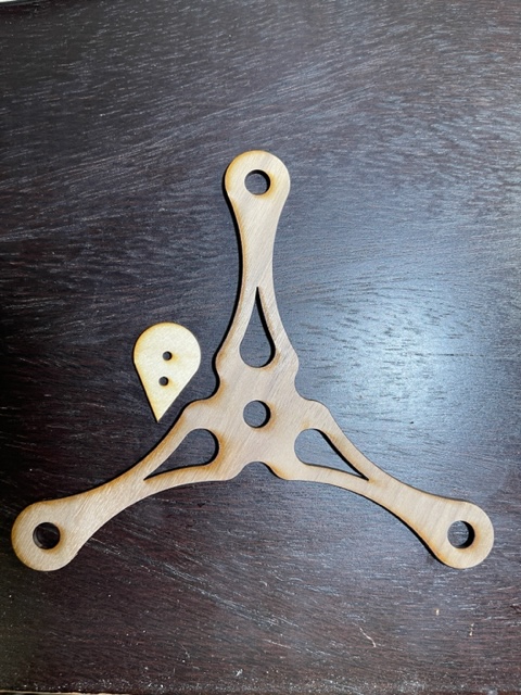
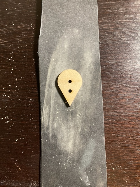
Before moving on to actually cutting out the parts that I needed, I generated a few test-cut profiles. I did this to size the holes properly for the actual material and kerf that I expected. I did this by creating a variety of small hole blocks which had holes with different amounts added or subtracted from the diameter. This helped me select the correct hole diameters for loose and tight fits. Following this, all the wooden pieces were cut out of the plywood using the Idea Forge laser cutter. This allowed all the pieces to be rapidly fabricated with relatively good dimensional accuracy from the sheets of material that I acquired. However, since the process of laser cutting can leave a residue or burn marks on the surface of the wooden components, I then sanded the face of each component using 600 grit sandpaper. This also helped to give the pieces a nice, smooth, finish before they were assembled. Pictures of the before and after sanding for several components are provided below. I hadn’t necessarily expected to spend as much time sanding each component as I did, but I am happy with the finish that it gives.
Assembly
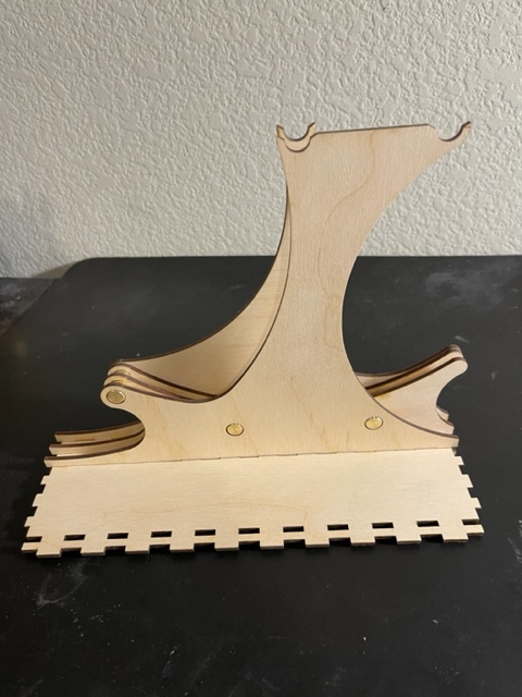
After I sanded each component I began the process of assembly. This step also took quite a long time because of the number of components involved. Additionally, since I designed several different pieces to have slight interference fits in an attempt to minimize the amount of glue required, several dowels were difficult to actually align and insert. However, this was successful in several locations. In the rear support assembly and the carrier for the planetary gear system (triangular walnut shape above), no glue is required and the final components are quite rigid. I began first by assembling the carrier for the planetary gears and the sun gear. I did this because it would allow me to learn more about the assembly process on parts that are relatively self contained. From here, I moved on to assembling the rear support assembly (left image below). At this point I had to use a pair of vice grips and a shop towel to hammer the pins into place. However, once the pins were in place the overall structure became very rigid and self supporting. While it took a lot of time and patience, I was able to assemble the rest of the gearing system as well. This had to be done carefully to avoid the veneer from chipping away, especially for the interference fit components. Due to the material warping, some of these fits were tighter than others, which caused some to be too loose or too tight compared to the design. As a finishing step, glue was added in several locations to help hold pieces in place and allow the gear system to actually function.
Conclusion
Comparing where I ended to where I started I am very happy with the progress that I have made. While the artifact that I fabricated doesn’t fully meet my functional goals, this can be remedied relatively easily by adjusting a few of the components. More importantly for this project, however, are the aesthetics. Comparing the product that I was actually able to fabricate to the original full CAD design I created, I am very happy with the final product. I think that it matches the aesthetic that I chose very well. The brass rods compliment both the lighter pine and the darker walnut, which help to differentiate the components of the escapement. While I have debated, and honestly continue to debate adding a finishing oil, I am happy with the product without a stain. I think that it adds a simplicity to the project which provides a welcome contrast to the complex designs. However, there are a few things that I would do differently given the chance. One of them is the finish on some of the brass elements. This is because I had to re-machine several of the pins, and while the finish is ok, slight misalignments in the lathe caused a far rougher finish. Given the chance, I would like to give these a smoother finish since, while it isn’t the most noticeable, it can detract from the design given close inspection. Additionally, I would avoid the compression fits that I initially designed. While they worked in many places, they also caused the wood to splinter in a few areas. This can mostly be hidden, but if I could avoid it in the future I would. Looking to the future, I plan on keeping my project and adjusting several of the components so it matches my functional needs. Even as it stands, I think that it makes a phenomenal desk ornament and a celebration of the mechanisms that my degree has covered. I will also be experimenting with applying a neutral finishing oil or potentially ebonizing certain components to further increase the contrast.

![]()