
Manufacturing proved to be very difficult over the course of this project. I began by creating a CAD model of my design and tweaking it so that it would be as easy to manufacture as possible. I then chose my materials and ordered them – the exotic woods were from Ocooch Hardwoods and the dowel, ball bearing, and acrylic sheets were from Home Depot. The first step was to figure out how to align the bores for storage holes on the bottom section once I had cut out the periphery of the shape, as cutting out the main shape would eliminate all reference points for alignment. My solution to this was to create a template in the shape that I wanted with a small .015″ indexing hole at the center. There were also indexing holes spaced 120deg radially at the desired center points for the storage cavities, and the dimensions for these were pulled from my SolidWorks model and cut using the Idea Forge laser cutter. There were several issues with scaling, cutting speed and power, and other technical problems, but I eventually was able to double-tape the template onto my purpleheart wood to create the bottom section.
![]()
![]()
![]()
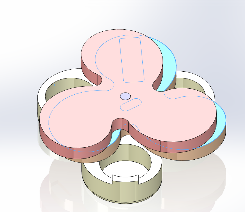
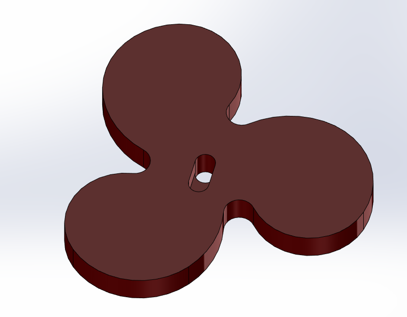
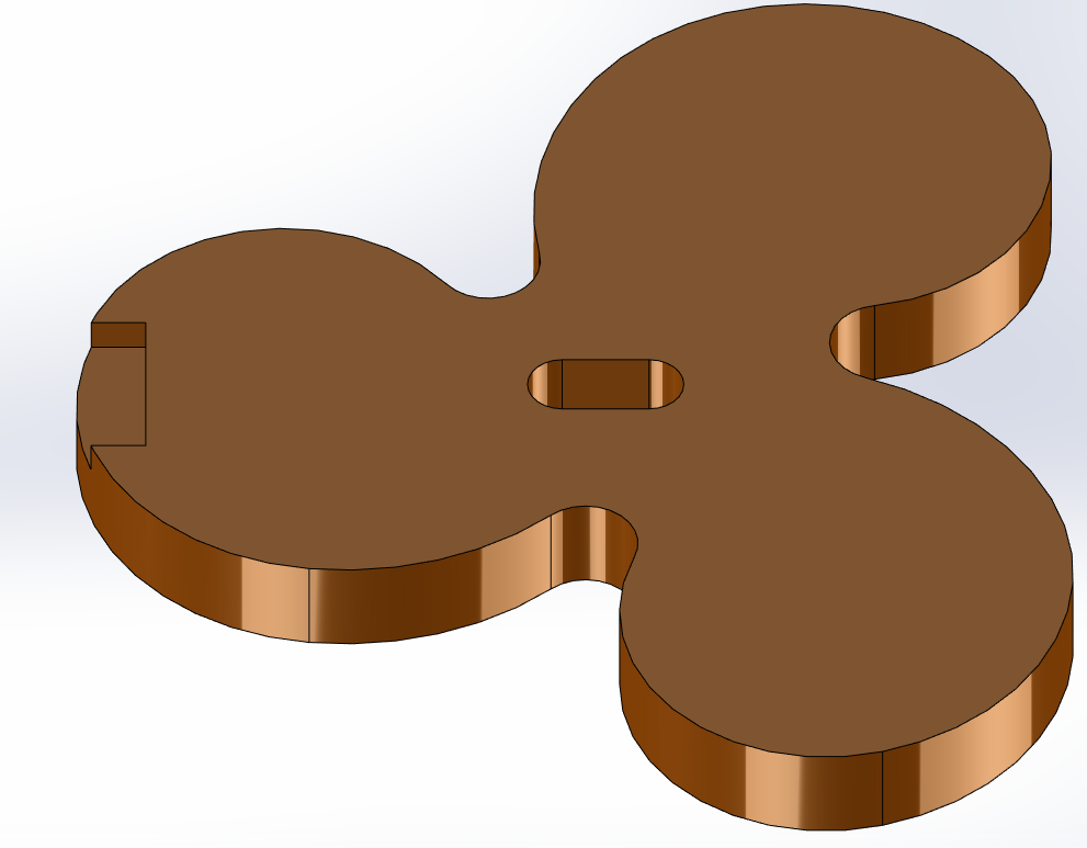
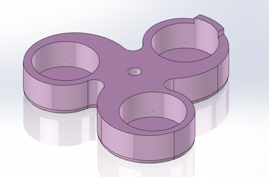
SolidWorks models of my individual parts and final assembly, as well as the template used for periphery and alignment.
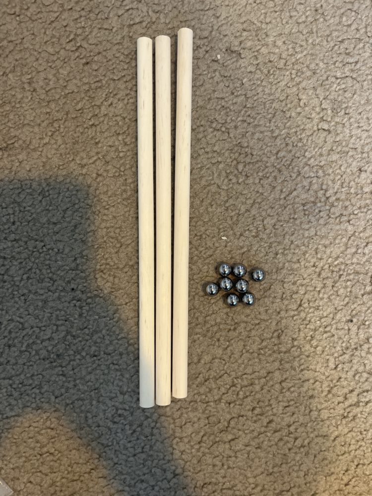
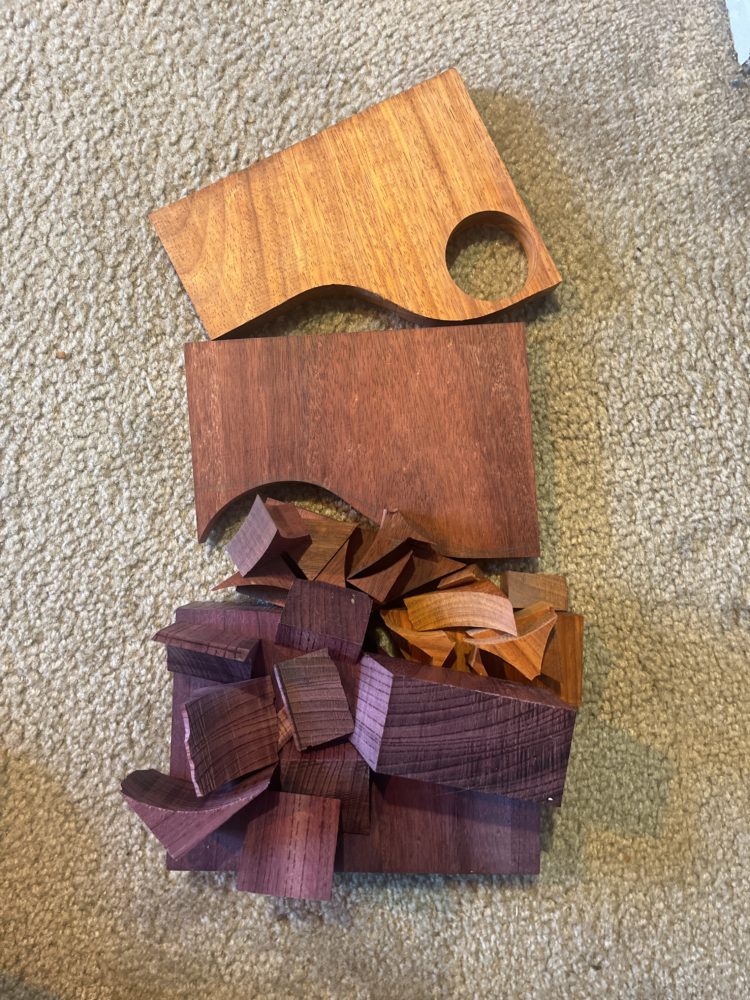
Some parts purchased from Home Depot and the remainder of the lumber I used for the project (S4S padauk, purpleheart, and bloodwood blanks).
I began by drilling through the center indexing hole with a 1/2″ brad-point bit, plunging through the template and into the wood in order to create the shaft for the central dowel. Before removing the template, I also made very small 1/16″ holes through the peripheral indexing points, just enough to mark the wood and provide a centering and starting point for when I eventually bore out the storage cavities. I then traced the template, using a washer to create a line that was offset from the template slightly, so that any mistakes with the bandsaw would not be serious. After removing the template, I took the part to the bandsaw and cut off most of the excess material, then realigned the template using two of the three 1/16″ holes I drilled before taking it to the table router. This was one of the most difficult parts of the process – the material was over 1-1/2″ thick and there was not a router bit long enough to follow the template on top and I would have had to flip the part so that I could not see the template and follow it from the bottom. In addition, the wood aggressively chipped out along the grain and burned unless it was moved very quickly due to the presence of natural oils. The density of the wood was also a challenge when trying to control the movement of the workpiece against the router bit. Mr. Colyer was kind enough to order a specialty bit for this purpose, and I waited a few days for it to arrive. This bit was very difficult to work with, and would pull the wood into the bit due to the fluting design. The gap between the bearing and flutes was large and required me to create a thicker template, which was difficult due to the laser cutter being constantly in use for several days. I finished the main peripheral shape for the bottom section and added a roundover on the bottom, but there is still some notable chipping.
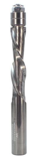
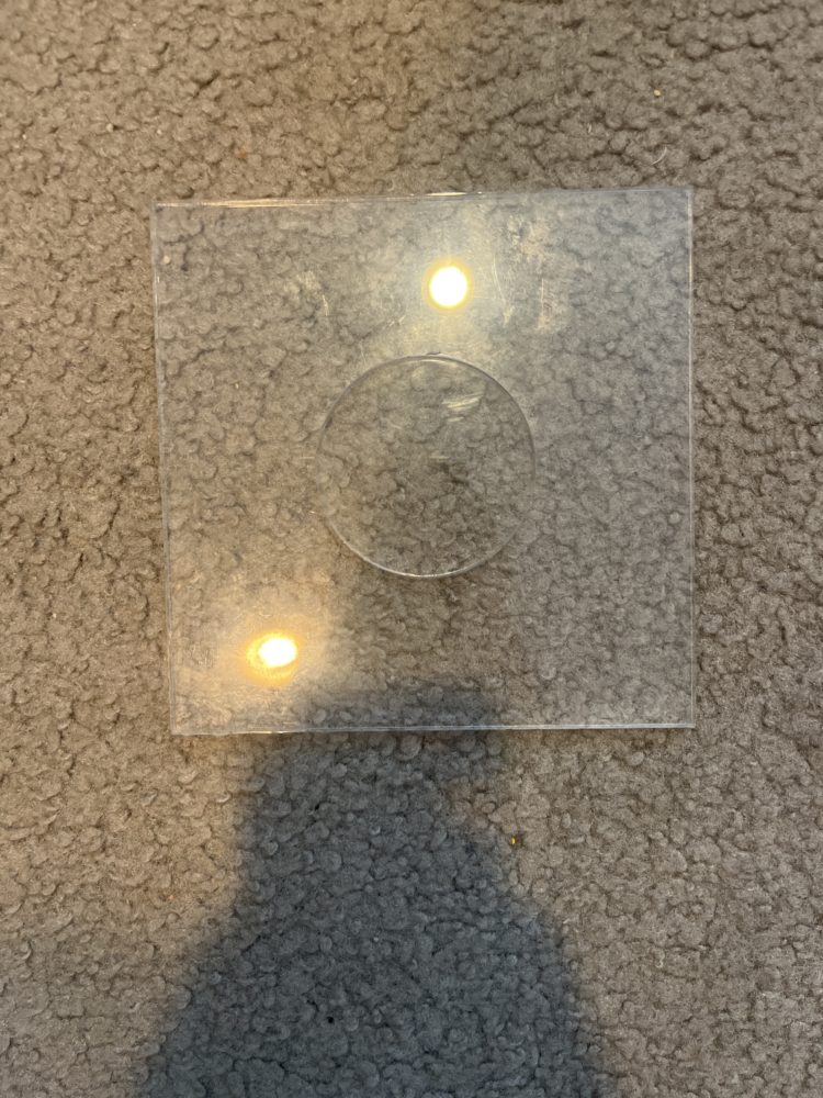
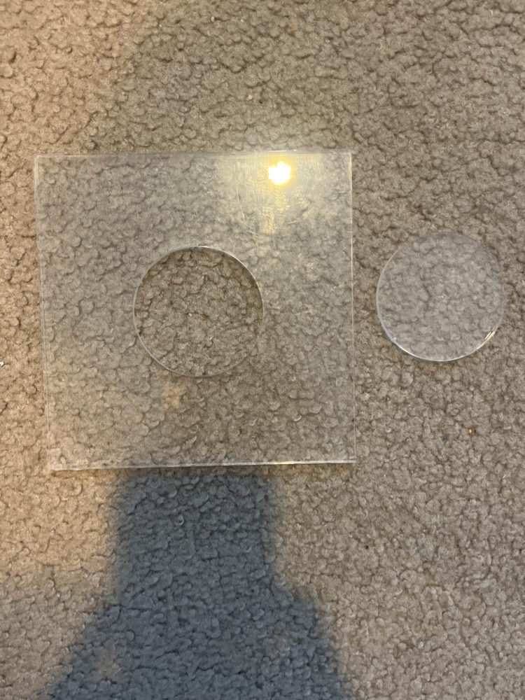
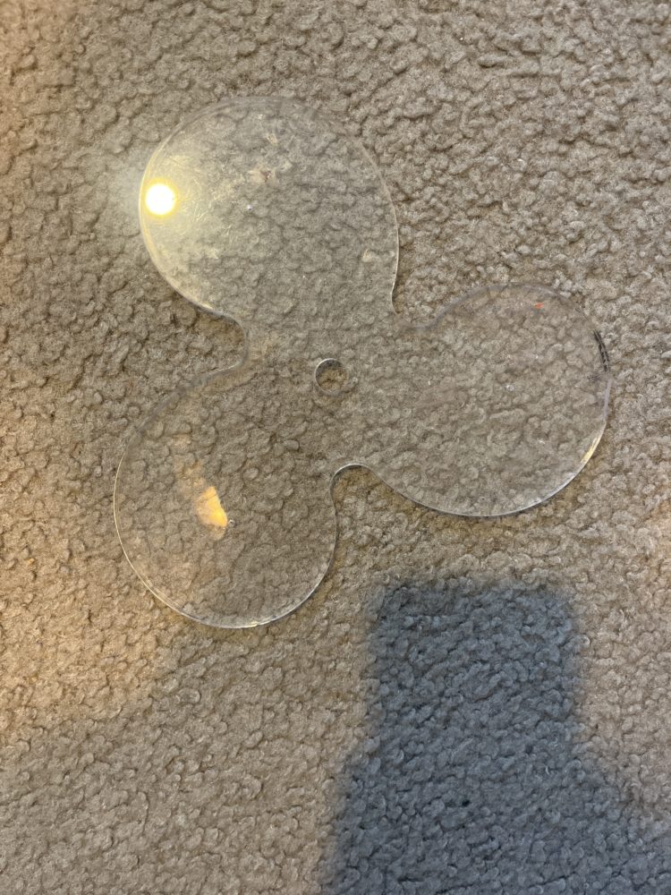
The specialty bit I used and the two-part storage cavity template I created.
I created a second template for the storage cavities, which was 6″ square acrylic with a 2.5″ circle at the center, and a concentric .015″ circle for indexing. I aligned the center point of this template with the center points I drilled into the wood earlier, secured it to the workpiece, and removed the 2.5″ center circle. Reducing the kerf on the laser cutter was a challenge here. I used a 2″ forstner bit to remove most of the material, and used a hand router with the template to finish out the cavities, making several passes. I repeated this for each storage cavity before moving on to the other parts. For the middle section, I adhered the template as before and drilled the 1/2″ centered through hole, traced it with a washer, removed it, and cut it on the bandsaw as before, then flush trimmed it with the template on again. I repeated the same process with the top section, then began to turn the central holes into slots. The one on the middle section had to align directly with the center of one of the lobes, so that it could translate in line with the restrictive tab, and the top section had its slot offset such that it needed to be rotate in order for the ball to fall from the middle to the top section. I did this by drilling another 1/2″ hole and chiseling out the remaining material. After this, I planed each section by sanding on a flat granite block and moved to the belt sander where I reshaped the parts all at once to remove imperfections and chipout by reshaping the peripheral shape slightly. From there, I went to the spindle sander, using a small diameter to smooth out the interior slots, and a larger diameter to sand the outside of the parts where there were tight curves. For finer sanding at P220, I used a random orbital sander, hand sanding the smaller, harder-to-reach areas and moving up to P320 in order to prepare for finishing. At the same time, I created a small cap to prevent the ball from escaping the assembly by hole sawing padauk and sanding a large chamfer into it. All that remains is to carve my design into the top (as a dremel tool has been difficult to find), introduce a tab, glue everything together, and finish the project (with Tru-Oil, a durable boiled linseed oil blend designed for gun stocks).

Some of my finishing materials, purchased on Amazon.
Many elements of this project are not perfect, and resulted from limitations of capability in the Makerspace woodshop and ITLL (the CNC machine was out of commission as well). I did my best to work around these constraints, but the qualities of the materials I chose, along with the tool and machine constraints, made my design very difficult to manufacture. In hindsight, I designed for myself a complex project which did not fit the timescale of the project, especially with capstone projects in other classes and frequent woodshop closures. However, I very much enjoyed working around these issues, although they were stressful at times, and learned a great deal of tips, tricks, and manufacturing methods which will help me in my career as not only a woodworker, but as an engineer and designer as well. I neglected to take very many photos throughout the process, but I hope that this was still very informative and descriptive of my work on this project!
A video of my final presentation
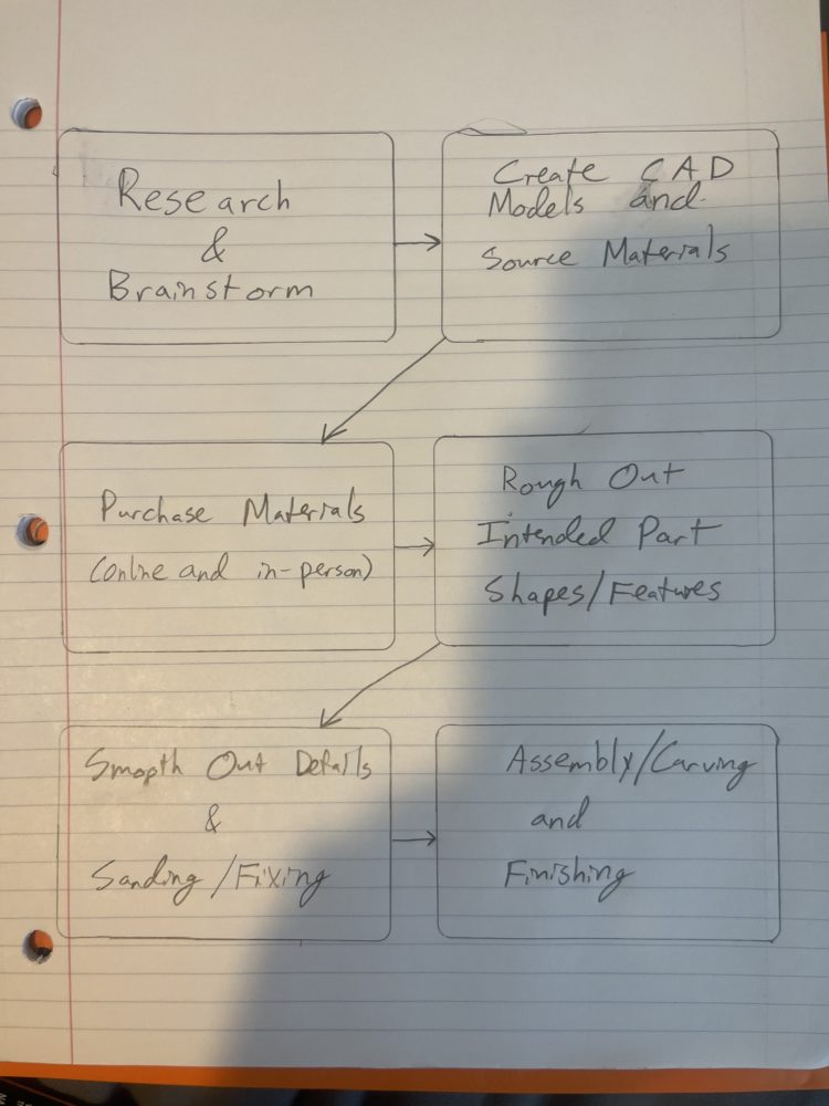

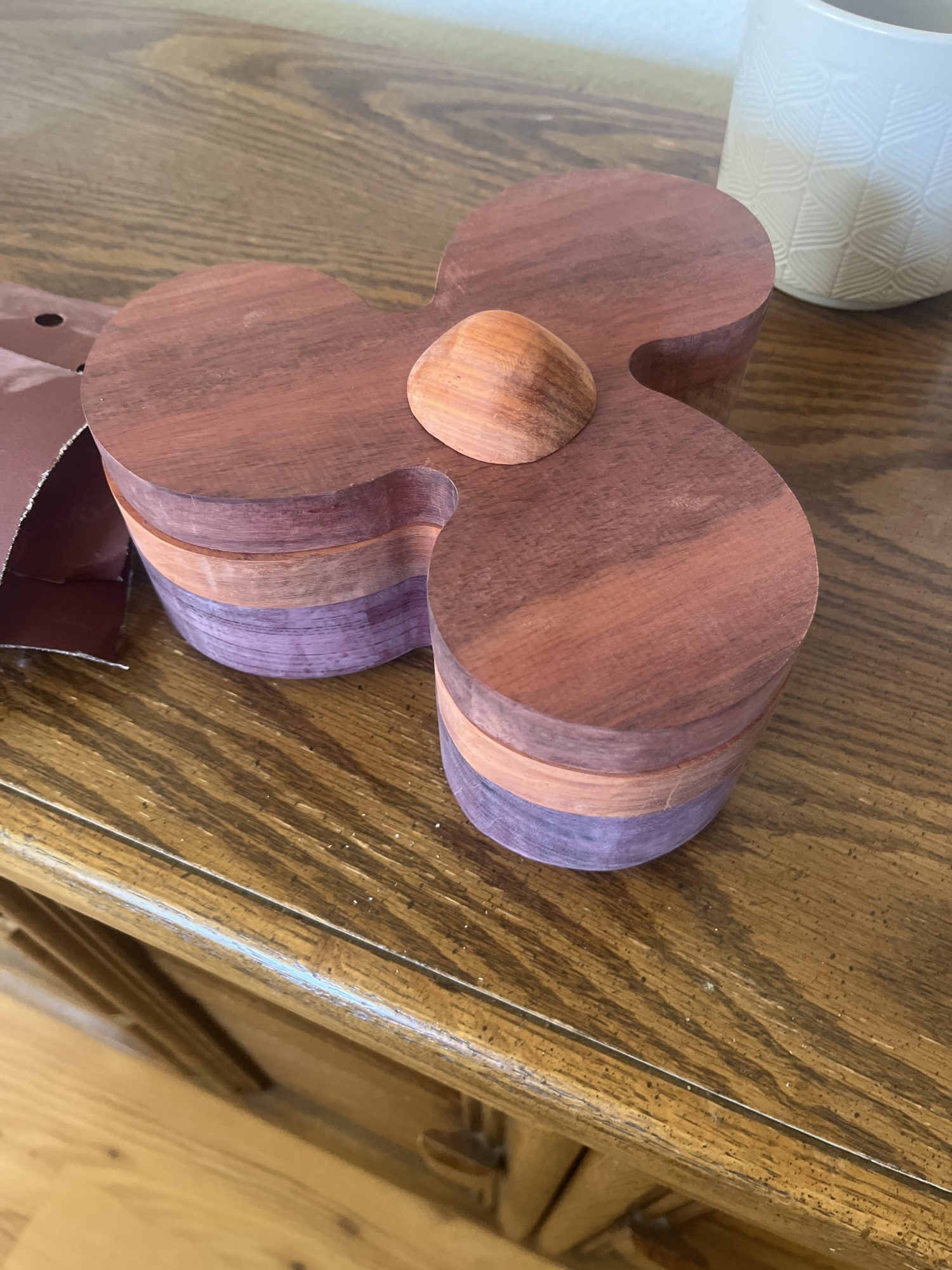
My timeline and an image of my final artifact pre-finishing.