
I’ve spent almost all of my time making this project in the machine shop in the ITLL. I started with a bar of aluminum and a Solidworks model of the face plate and back panel. The most important part of the project is the face plate because it is the main thing people will see when they look at the headphone amplifier. It holds the power button, volume knob, input selector knob and the headphone output jack. For this reason it was going to be the part I add my aesthetic to because the back panel is firstly on the back and no one will really see it, and it doesn’t need to look fancy it just had to work in terms of the types of connectors that the amp needs.
I first cut the bar of aluminum on a band saw to just over the final length I needed in order to leave room to remove material and get a nice surface finish on the part. I then faced the top and the bottom down to the desired thickness using a facing mill.
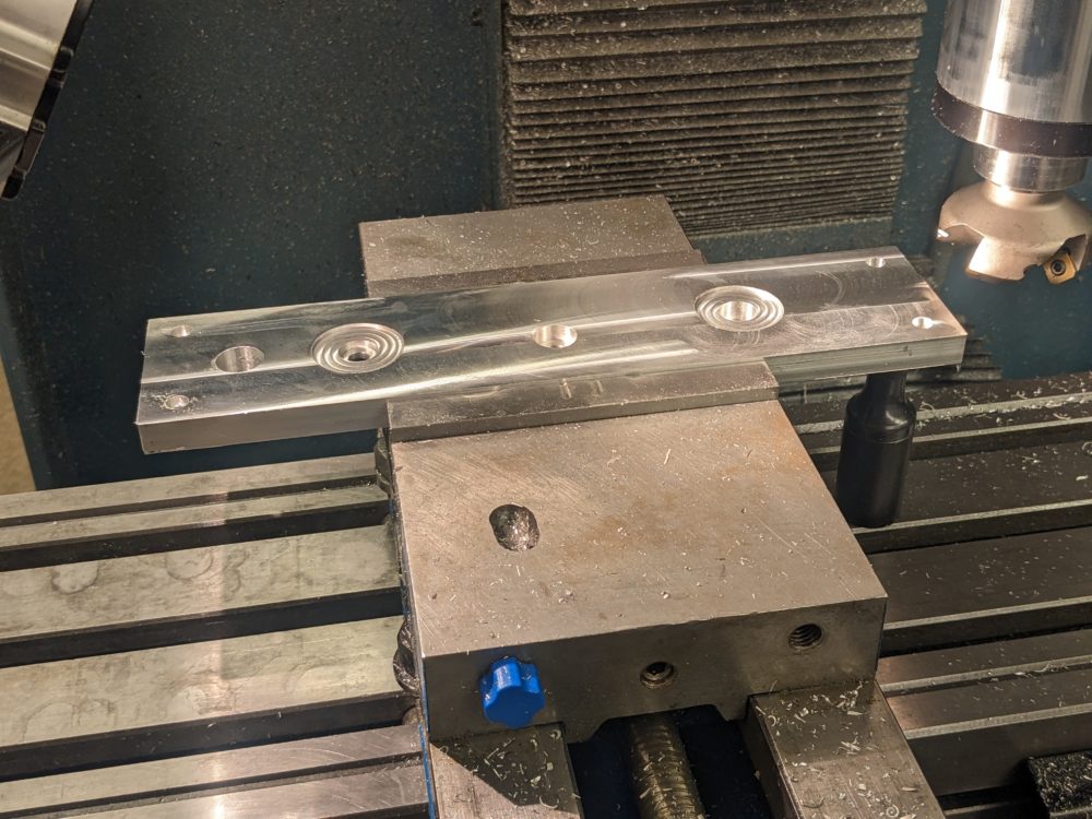
Once that was done, I programmed MasterCam to machine out the features I had in SolidWorks that couldn’t be done by hand. This included the contouring of the outside, the cutouts for the knobs and a relief pocket on the backside for the input selector.
After some time and some set backs the part looked like this:
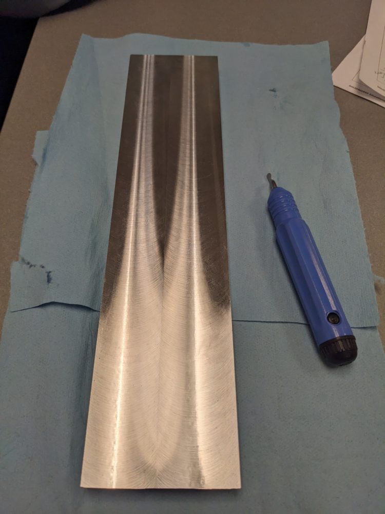
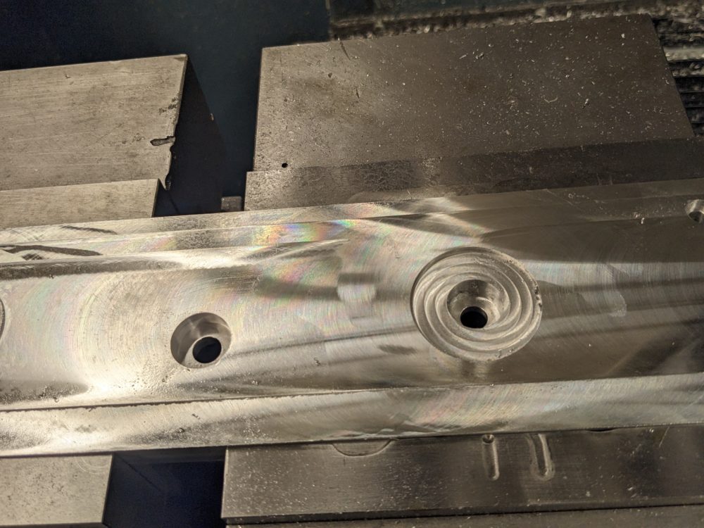
The most important element of this part was the Cote de Geneve finish that I was aiming to add to the front surface. Since this finish is so precise and if I messed up the part it would take a lot of work to fix, I made test pieces out of smaller scrap aluminum to get a feel for how to actually make the finish and so see which orientation I liked best, horizontal or vertical. To actually get the finish, the same facing mill used earlier passed across the face with a slight offset from the previous pass (~90% overlap from the last pass) to only cut with the edge of the facing mill. Each pass had to be .0005″ deeper than the last because it had to actually remove some material to get the finish on the part, but if the cuts were too deep, one side of the part would be much thicker than the other which is undesirable. 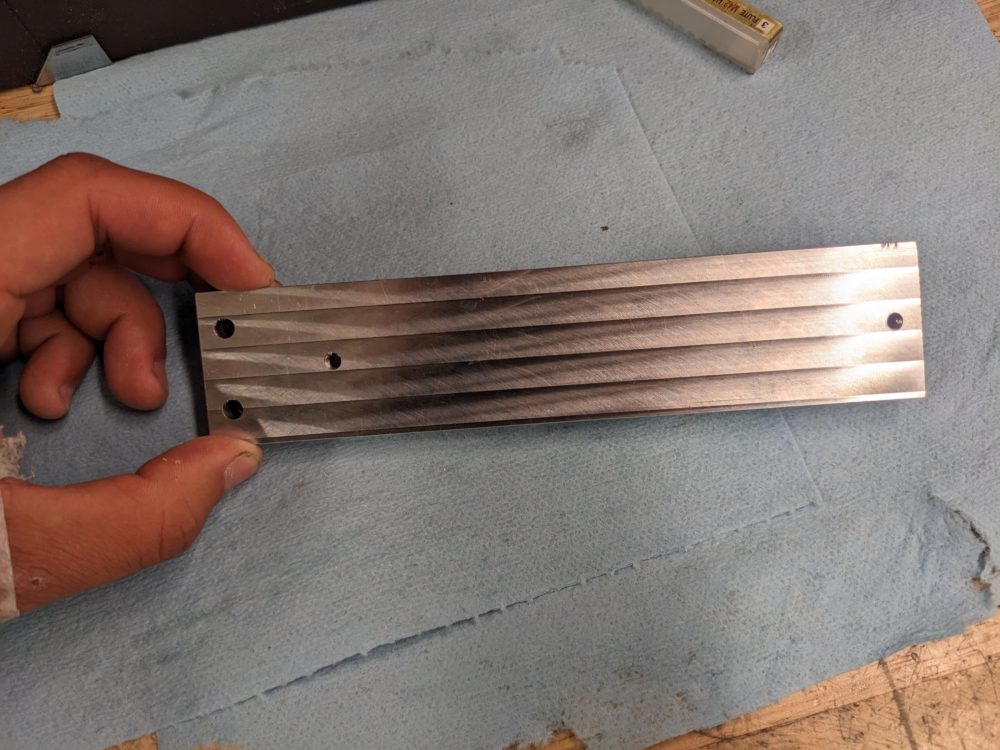
Once I felt like I had a good hand of the technique, I began adding the finish to the actual part. This is where I ran into some major issues with how the part was fixtured in the mill. Since the depths of cups were only .0005″, if there was any misalignment of the part, it would either cut too deep, or not at all. Below is a picture of my first attempt at the finish which you can see it very messy and not uniform at all. There is no distinction between the lines and in some spots the cutter was not making contact with the part.
After some time refixturing the part I decided to make vertical lines because it would get rid of any flatness tolerance across the wide face of the part, and instead only deal with the tolerance between the top and the bottom which is much less. In the end I am really happy with how the surface finish came out as it looks really clean and is exactly how I imagined it to look.

Don’t mind my hand, I ate it on my bike.
In keeping with the mechanical watch aesthetic, I found some flat head shoulder bolts screws that looked a lot like the fasteners found on watches. The shoulder was a little too long for the part, and the thread was not the right size, so I cut off the stock thread and tapped the shoulder with the right die so it would now fit into the face plate and body of the case. The last major part I had to make was the back panel with all of the connectors. Since the amplifier would have four inputs, there were four sets of RCA connectors, and there were also two XLR outputs with accompanying RCA jacks above it. This part was relatively easy to make as I just had to find engineering drawings for the XLR connectors on google and drill out the holes to the right diameter and right location. 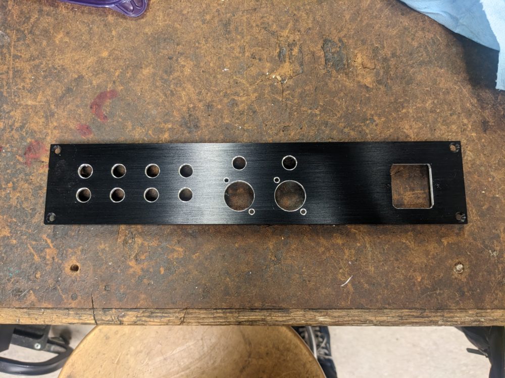
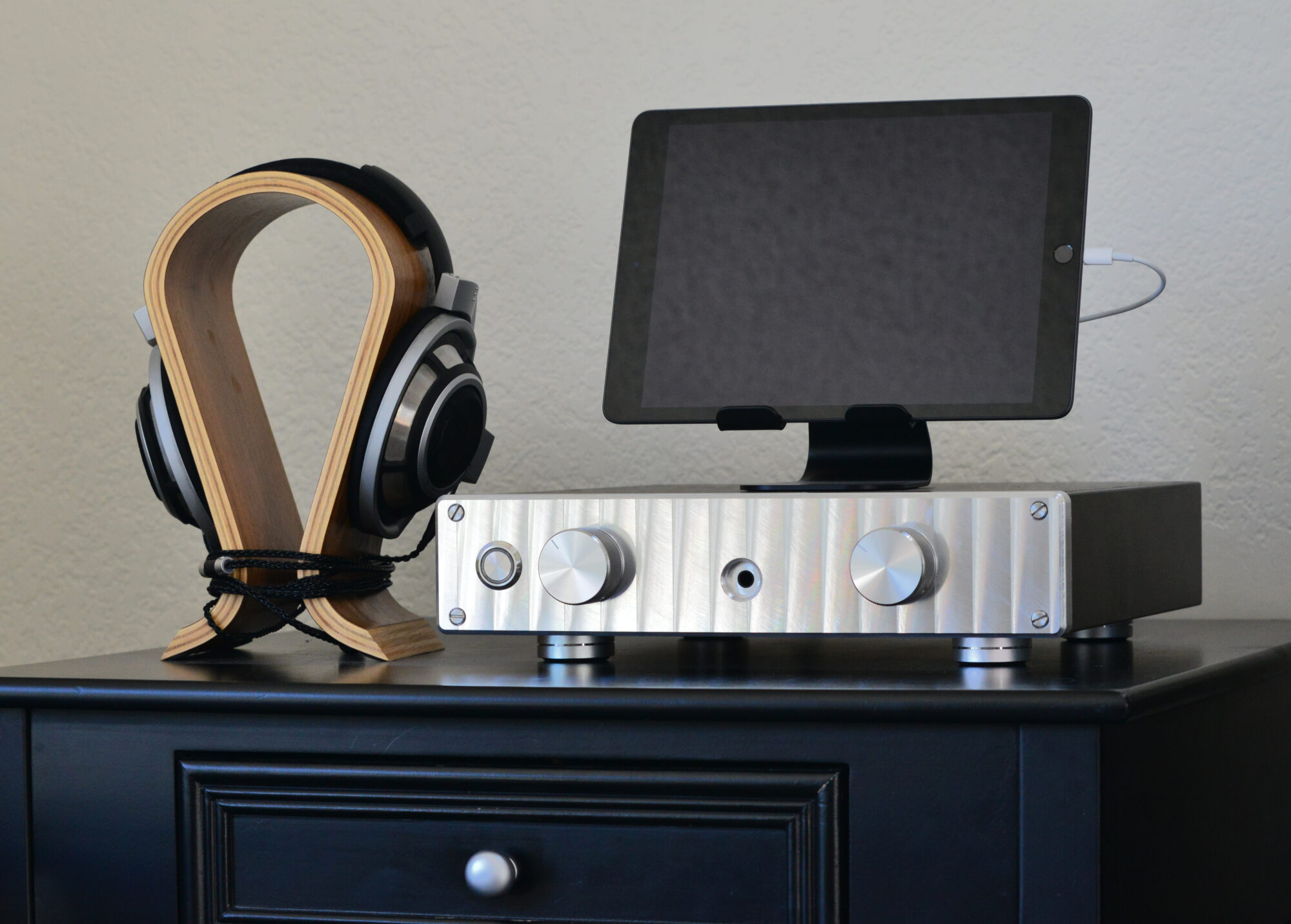
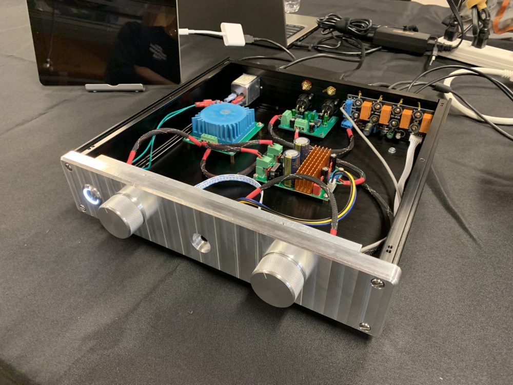
Below is a photo of the headphone amplifier fully assembled with the lid taken off so you can see the inside. This was the configuration that the case was displayed in for the class expo. To test off the functionality of the device, there were three media devices that could be used to play music, as well as two sets of headphones that people could use to hear the quality of music from the amplifier. Users could switch between the inputs with the input selector knob on the left and adjust the volume with the knob on the right. The two headphones required different amounts of power to play music, so people were able to swap between the headphones while keeping the volume the same and hear the difference in volume out of the headphones. This served to show case the reason for such a large device as a phone would not be able to power the headphones.
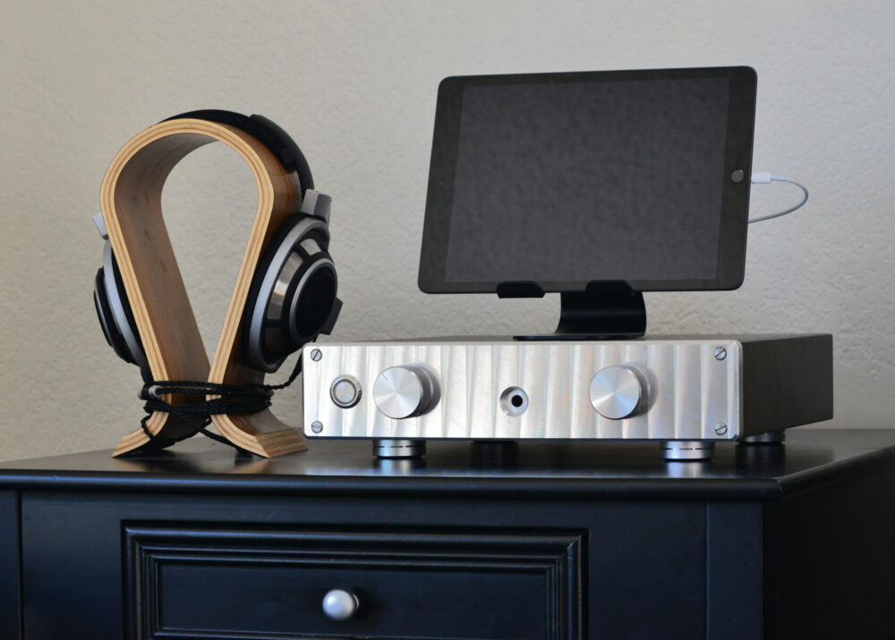
This is the final set up I have at my house with headphones and an iPad for streaming.
1 Comment. Leave new
That front plate came out beautifully, I especially like the spirals where the knobs go. I know they will be covered up by the knobs, but if you every make another plate you should consider making the whole plate a spiral or extending the knob holes to show the spirals.