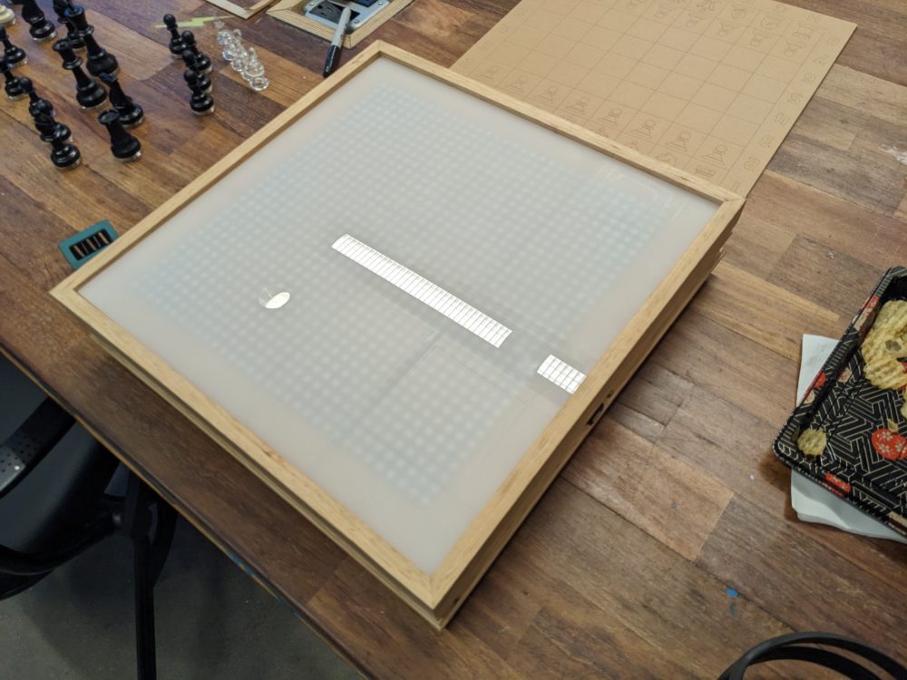
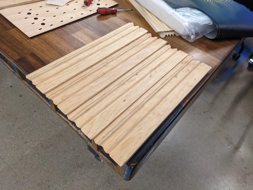
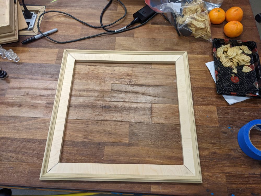
To upgrade the 4×4 prototype to the finished 8×8 board, my first focus was to build the full-size enclosure. I decided to use trim moulding to create a distinct pattern for the sides of my box. I needed additional height to allow the acrylic to sit within the frame, so I also constructed a secondary platform for the base to sit on.
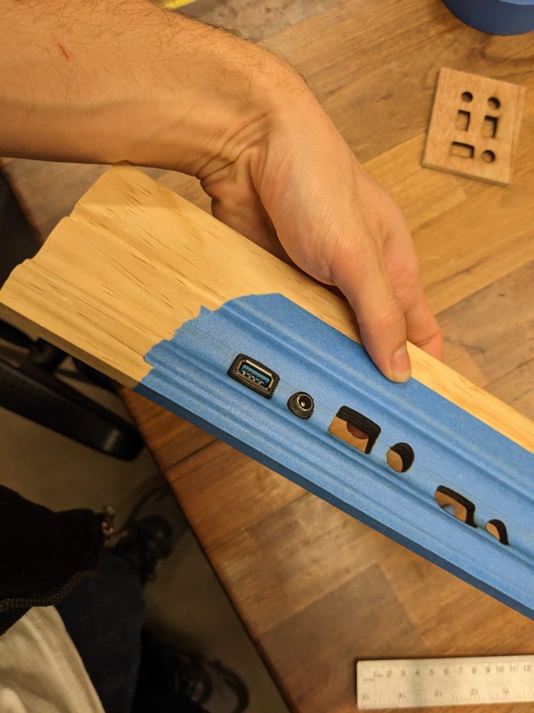
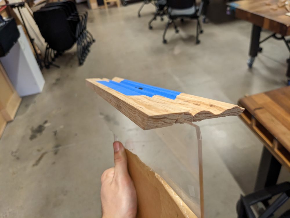
A huge priority for me was the inclusion of ports that would allow me to easily plug in a USB cord connecting the Arduino to the computer, along with an additional port for the external power supply required to light all 1024 Neopixels. I spent several iterations of laser-cutting attempts to get the size of the ports just right, but I am very pleased with how well the ports were cut on the curved wood of the moulding. Another addition I included was the notches cut into the back of two of the panels. These allow me to insert a piece of acrylic that supports the base containing the wiring and Arduino.
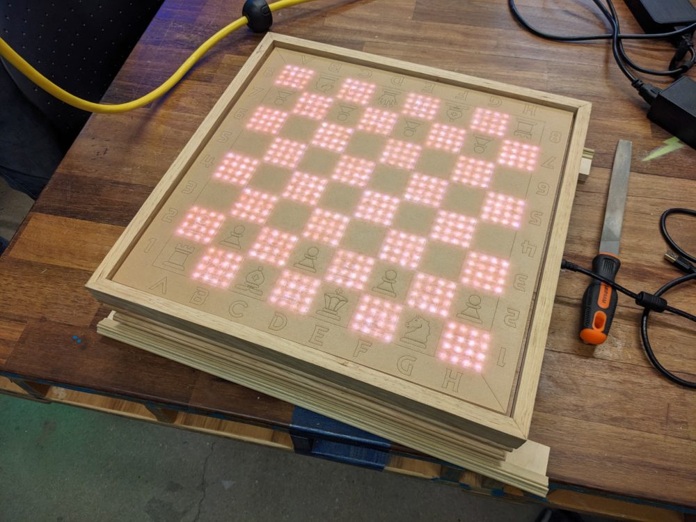
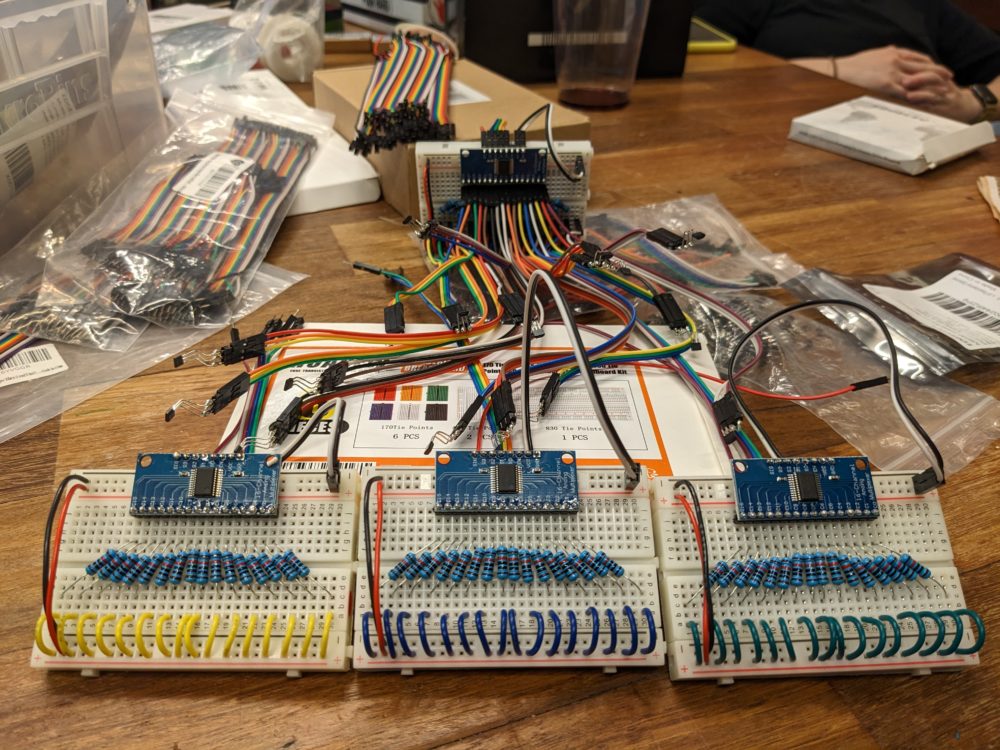
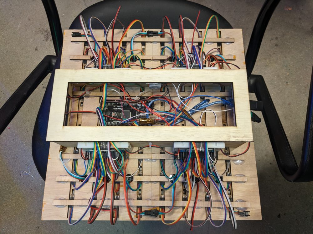
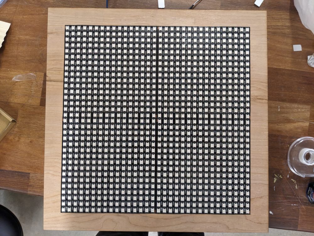
Speaking of the wiring, I had to scale the previous version fourfold. This required me to construct another 3 breadboards. This was a tedious task, but it reminded me of my Twisted Wire Bonsai Tree project with the feeling of Zen I experienced during it. I laser-cut the full 8×8 board with the holes included for the Neopixel wires, and added supporting walls that the breadboards could be connected to. Another tremendous task was the physical act of placing all 64 Hall Effect sensors in the right spots. I used Wago connectors to connect all power and ground lines before plugging the various pins into the Arduino. With the wiring completed, I added another panel to lock everything down, with the help of a plentiful amount of hot glue throughout the whole process.
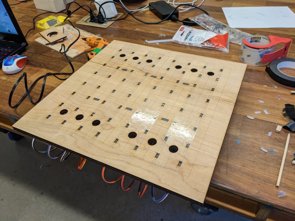
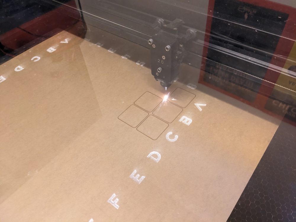
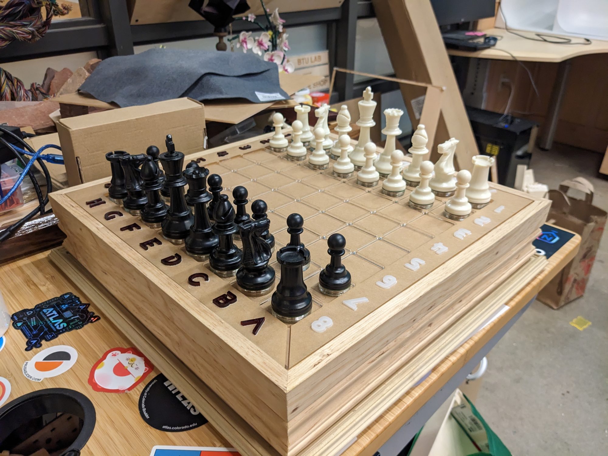
Finally, I combined the outer frame and the inner wiring together to create the foundation of my Chess Board. Practicing the same techniques as used in the 4×4 prototype, I laser-cut a layer of frosted acrylic that covered the Neopixel grids to diffuse light. Above that went another layer which had the engraving for all the squares and grid axis. I also included symbols on the squares to indicate where players should put pieces to reset the board. I think this is a critical addition for new players who might not necessarily know how to reset the board, meaning the piece detection wouldn’t work properly either. The final layer was cut from transparent acrylic and places borders demarcating individual squares. This is necessary because the magnets in the pieces are strong enough to repel each other off their squares without the border layer. The final addition was the White and Black grid axis, which bring a much needed splash of color to the board.