
Background and Purpose
My family is originally from Germany and, therefore, I love to drink sparkling water. I prefer sparkling water over regular water because I find it more refreshing. As a result, I go through many aluminum cans which all end up in the recycling bin. Each aluminum can takes up a substantial amount of volume in my recycling bin which means I need to empty it more often. In Michigan (where I grew up) you would get a store credit for bottle return which is not possible where I am currently living. Therefore, I will be making an aluminum can crusher which you can place the can into and then crush it. Through this process I hope to learn more about woodworking and the different tools and techniques required to add various design elements to a piece of wood.
Vision and Specifications
The functionality of the device is important as its main job is to crush aluminum cans with ease. Human factors must be considered when designing the device because it will be human-powered. Any components that interface with the user must not be too long or short, because this can sacrifice and negatively effect the ergonomics as well as the power and force needed to be inputted by the user. The user will be crushing the can using their strength by taking advantage of leverage and physics and the user is considered to be the average adult. The user should not have to apply more than 20 pounds of force to the lever to crush the can. A standard 12 oz aluminum can is 4.83 inches tall and the device must crush the can to a new length of 1.75 inches or less. The device should also be able to accommodate a standard plastic water bottle so the feeder must be greater than 8.5 inches. After the can or plastic bottle gets crushed, it should automatically be dispensed from the device out of an opening in the side. The force of gravity will be used to remove the crushed object out of the feeder and it will then automatically fall into the recycling bin. It is paramount that the design is safe to use and the user has a sturdy handle to hold on to. This means that there are no sharp edges or points at which the user could cut themselves or pinch themselves. The device should also have channels where the countertop can slide into. This will ultimately keep the module from sliding across the countertop or from being flipped over if the user inputs a force at different angles.
Artistic Vision and Aesthetic
The artistic vision I have for the device is that it has clean curves and is uncluttered. The profile of the design when viewed from the side takes on the aesthetic of an airfoil. An airfoil, also known as an aerofoil, is a shape designed to produce lift when air flows around it. It is a key component of wings on airplanes and other aerodynamic surfaces. The shape of an airfoil is asymmetrical, with the upper surface (known as the upper camber) typically curved more than the lower surface (lower camber). This asymmetry contributes to the generation of lift. This profile will cover some of the moving components and linkages that are used for the mechanical design. Because of this, the design will have a hint of minimalism as the profile of the wing and the lever handle are the only components that can be seen when seen from the side. The material I will be using for the profile of the airfoil will be a high quality wood of a darker tone such as shedua or walnut. The components that need to handle larger forces and stresses will be made out of high quality maple. Maple is a very strong and dense wood and has material properties which make it an ideal material for the mechanical components.
The aesthetic goals for the design are that it will look aerodynamic, with a hint of minimalism. The wood itself is not an aesthetic, however, it does contribute to the aesthetic by adding natural warmth, texture, and organic qualities. The beauty of wood lies in its diverse grain patterns, colors, and the way it responds to light. The lighter and darker color of the wood will be complemented and contrasted well by the lighter toned countertop. There will also be an industrial aesthetic that the design will introduce into the space when looked at from above because all of the moving pieces, linkages, fasteners, and other components of the mechanical device can be seen. The main component of the design will be the aerodynamic profile of the airfoil.
Alternate Aesthetics
The airfoil design was originally an alternate aesthetic and I decided to go with this alternate aesthetic because I liked the profile of the airfoil much more than the original industrial aesthetic goal I had in mind. The aerodynamic aesthetic gives a more modern touch and flair to the design which is something I identify more closely with.
Originally, the main aesthetic I was trying to achieve was the industrial aesthetic. The design also incorporated a sense of minimalism because the industrial aesthetic tends to embrace a minimalist approach, focusing on mainly the essential elements and components. The design would have had a more neutral color palette dominated by shades of grey, black, white, and earth tones. This color scheme would have complimented the raw materials and, therefore, contributed to the overall industrial ambiance.
The last alternate aesthetic I had was a motorized and dynamic aesthetic as seen in Figure 1. This design included having an electric motor which would be geared down using a belt drive system. This design was originally my favorite as I thought the moving parts would add a very cool component to the aesthetic. Ultimately, the device would have been unsafe as your hands or other objects could get caught into the very fast moving components. I also do not have the space for a larger system like this as storing it would have been an issue in itself. This aesthetic and design was influenced by RPG Woodworking [1].
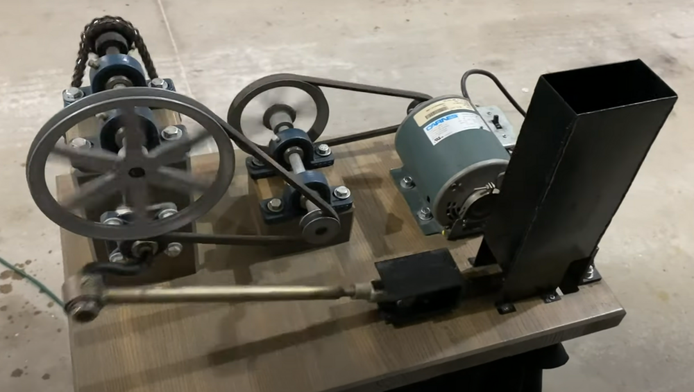
Figure 1
Initial Sketches and Prototyping
In order to eventually decide on a design I translated my ideas and thoughts onto paper. I performed a lot of research and benchmarking to see what products and devices are already out there. The main take away from this was the overall mechanical design of the system as seen in Figure 2. [2] I started by sketching the side views and profiles of the devices to get an understanding of the various profiles and how I could modify them as seen in Figure 3 below. Up to this point I did not even consider using the airfoil design as the profile.
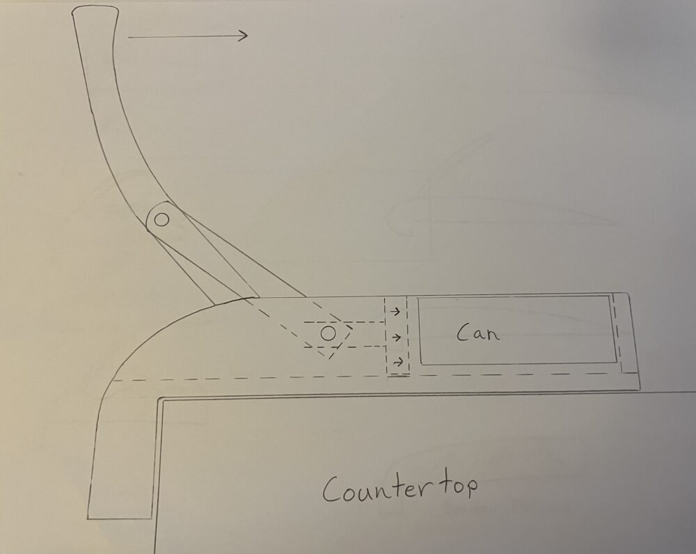
Figure 2
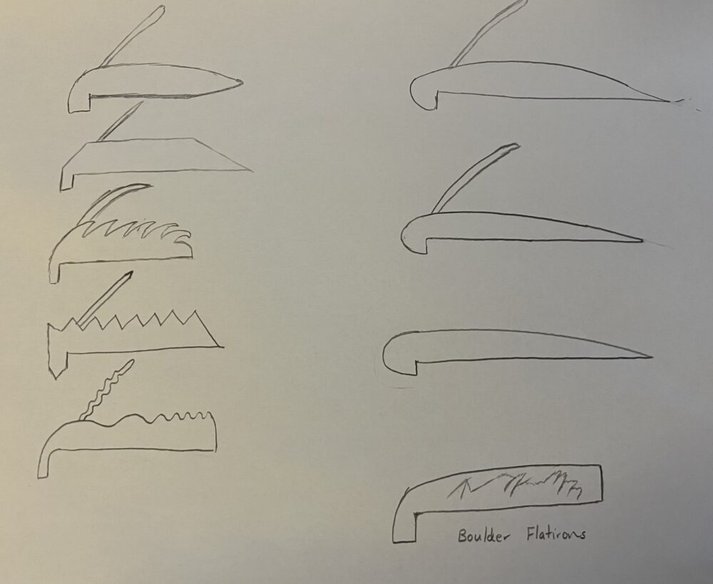
Figure 3
After sketching these designs, I wanted to get an understanding of the required forces that would need to be inputted and how this would effect the ergonomics. When I was researching, I found that it takes approximately 50 lbs. to crush and aluminum can [3]. However, when I experimented with crushing cans with my foot, I used a scale to approximate how much force they could withstand before they collapse. I was surprised with how much force they can withstand because some didn’t crush until 80 lbs. I made a lever and a linkage out of a piece of cardboard (as seen in Figure 4) and a broken hockey stick hockey stick to figure out a comfortable length for the lever that would optimize ergonomics and leverage allowing the user to crush the can with ease. I came to the conclusion that the lever arm should be 24-25 inches in length and the linkage should attach 5.5 inches above the base and be 7 inches long to allow for larger water bottles or cans to be crushed. This ultimately gives you about 4.5 pounds of crushing force on the can for each pound of force the user exerts on the lever. For the typical can the lever will be upright allowing the most force to be exerted at this point which is the most ergonomic position throughout the movement. As soon as the can gets crushed and dented, the force needed to be applied decrease substantially making it easier for the user.
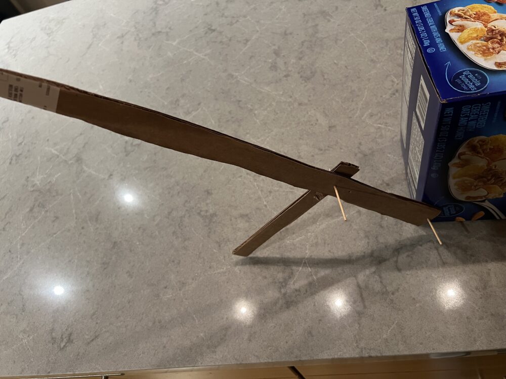
Figure 4
Final Design
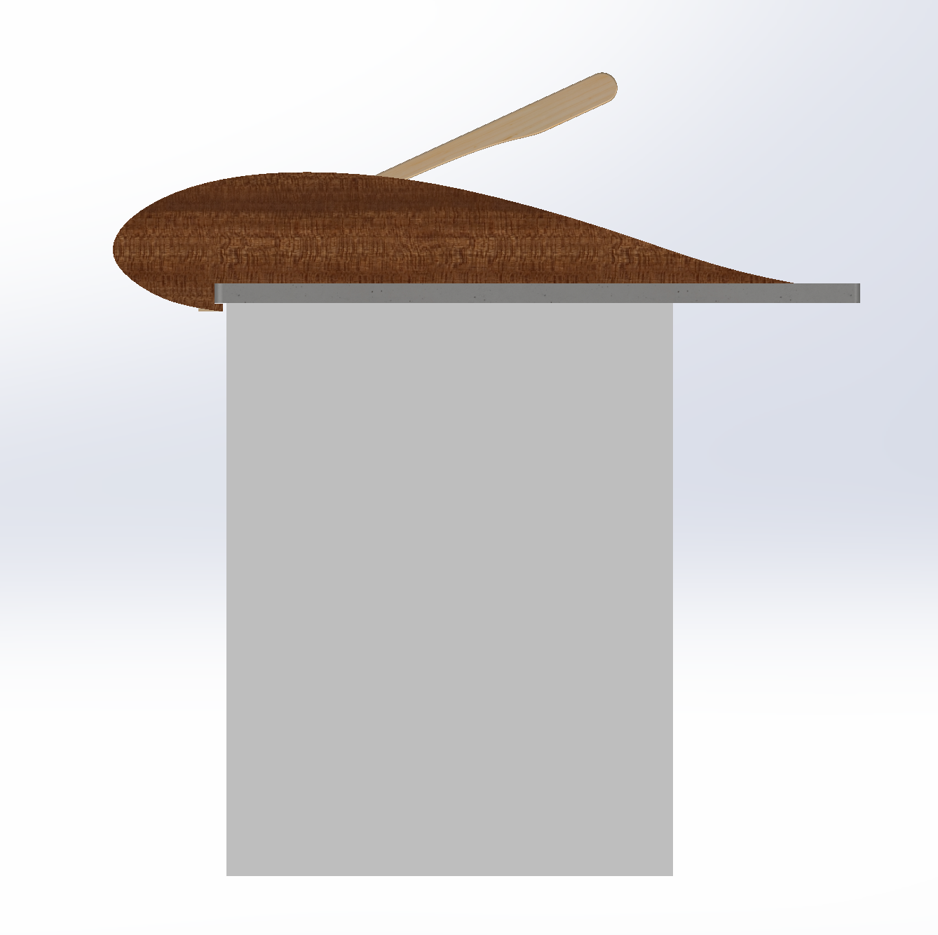
My final design will implement two different kinds of wood. The mechanical system will be made out of maple, a stronger and denser wood, while the airfoil will be made out of a darker colored wood. The design looks sleek and uncluttered when seen from the side as seen in the left and right images of Figure 5. When seen from above, the components that make up the mechanical system are visible giving it a more mechanical and industrial aesthetic.

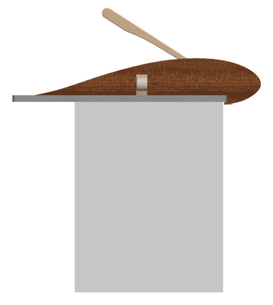
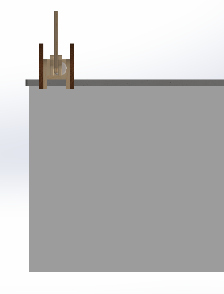
Figure 5
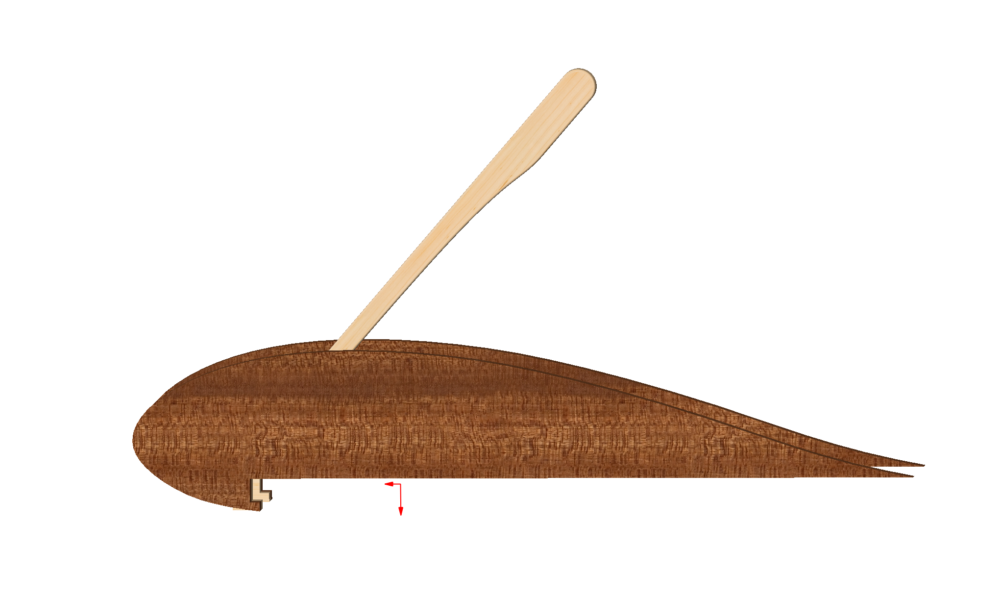
Figure 6
Figure 6 depicts airfoil profile of the aluminum can crusher as it looks without the countertop seen in figure 5. There are slots in which the countertop will slide into in order to keep the system from sliding or flipping over if the user inputs a force at different angles.
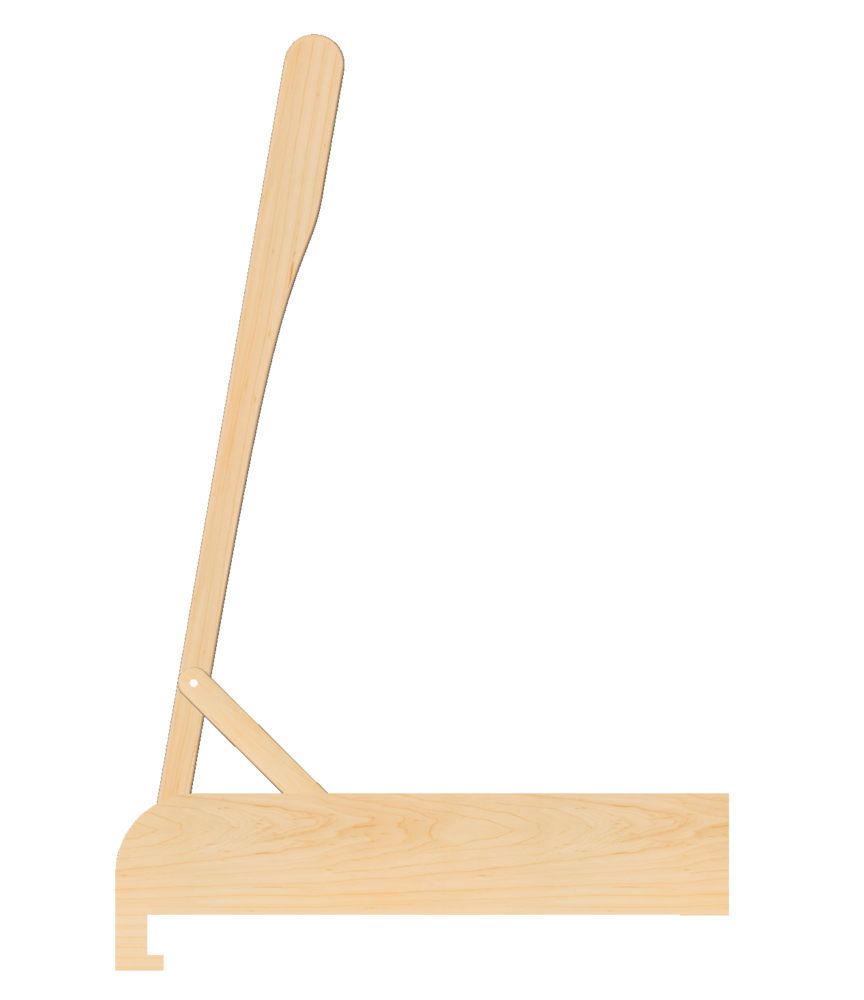
Figure 7
Figure 7 depicts the mechanical module of the overall design which will be made out of maple. This is what needs to withstand the forces needed to crush the aluminum cans.
![]()
Figure 8
Figure 8 shows where the can will be before it gets crushed. The user will press forward on the lever with 10-15 pounds of force and watch the can collapse. Once the can gets crushed, it will automatically roll down the shoot and into the recycling bin below.
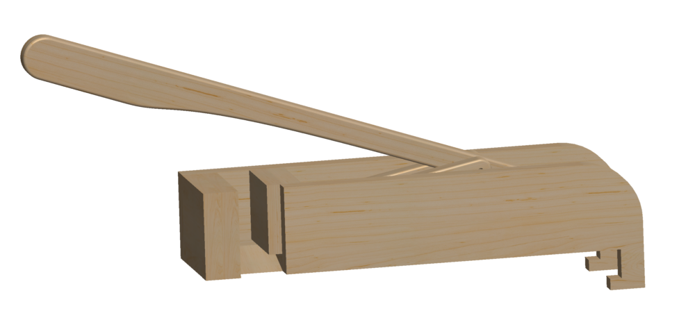
Figure 9
Figure 9 depicts the can crusher in the position when it has completely crushed the can. The crusher will not extend further than it is as seen in the figure, because there is a rail system in which the crushing plate will slide in. This feature can be seen in Figure 10 where the slot keeps the can crusher in the correct position as it crushes and releases. Their will be a radius on each end to prevent the system from seizing, ensuring a smooth and efficient crush for each can.
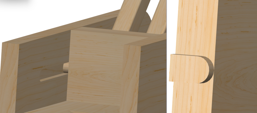
Figure 10
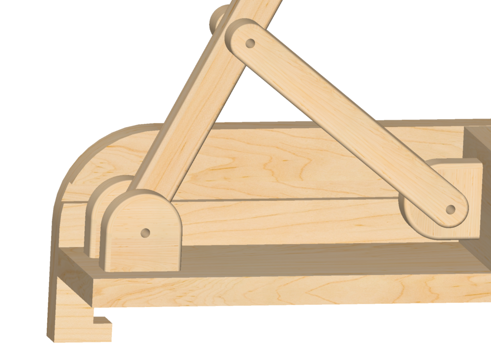
Figure 12
Figure 12 depicts the linkage system and how the forces get transmitted to different components of the system. The fasteners that will be used for this project are polished, stainless steel binding post screws. This will minimize the wear and tear on the joints as the fastener has a smooth finish. If a bolt were used with a nut, the treads of the bolt would erode the maple over time.
Manufacturing
Timeline
Week #
- Final design adjustments and modifications.
- Purchase materials (Maple, Oak or Shedua, Screws)
- Begin Manufacturing
- Continue Manufacturing
- Complete Manufacturing
- Complete additional Manufacturing needed and complete the Design Report
One of the reasons I am choosing to work with wood, is to learn more about wood working. I do not know all of the tools and techniques that will be used to make this design come to life. From what I have learned from past experiences, I will be using a table saw and miter saw to cut pieces down to size. A band saw will also be used to cut the wood into custom shapes such as the airfoil. A router tool will be used to add a 1/8 inch roundover to the linkages and the lever. I will be using wooden glue and screws to join the various pieces together. Pilot holes will be drilled prior to screwing each piece together.
Credits and References
[1] Danimal’s House: https://www.youtube.com/watch?v=S1rUooUhZAo [2] RPG Woodworking: https://www.youtube.com/watch?v=6JiS1TmXhyI [3] https://patents.google.com/patent/US4290354A/en#:~:text=An%20actual%20testing%20of%20the,5%20pounds%20to%2020%20pounds.
3 Comments. Leave new
Have been mulling this idea for awhile myself. Your initial sketches are great as they stretch your imagination, they are great because you’ve done hand to paper, not computer modeling. Am interested further in any advance you may make in allowance for multiple loading; like a hopper or some such. Your paper explains your position and thinking quite well. I like the curved design as I’ve a lifelong interest in small wooden boats. Try more than one build at a time, this allows forward movement if you experience any type of material failure,and you can allow another to try your design and still have one at hand. C
Hi Tim. I think that you have a solid idea and a great plan. Airfoil is an interesting aesthetic choice that I have never heard of. Are you concerned at all about the longevity of the piece when it comes to functionality? I know that keeping wood fastened and sealed over time proves to be a challenge, so I’m looking forward to seeing what you come up with!
Tim I really like this concept and project. I think the airfoil design is really cool and really adds to the overall aesthetic of the project. I was wondering if you are going to use any sort of wood stains to color the wood in addition to using different types of wood. Staining could be very cost effective for getting the coloring you want on each component. Excited to see the finished project!