
For my final project I have decided to take the dramatic landscape of the flat iron mountain range as inspiration to create a piece of wall art that dynamically changes to match the outside light that a photoresistor is detecting through communicating with the control board. I have chosen this minimalist nature aesthetic as my final project due to the fact that it involves multiple layers of my engineering skills and my previous work as an electrician into a singular piece that I will be able to enjoy for years to come. To accomplish this project I decided to use four critical components that came together for my finalized design. First is an acrylic laser cut piece that will resemble that of the flat iron mountain range, second is a strip of individually addressable WS2812B LED lights, third is an RedBoard which handles the coding necessary to accomplish the dynamic aspect of my project, and finally a photo resistor that will detect the amount of light outside to send vital information to my RedBoard that controls the light setting that creates a backdrop to my flat iron mountain range.

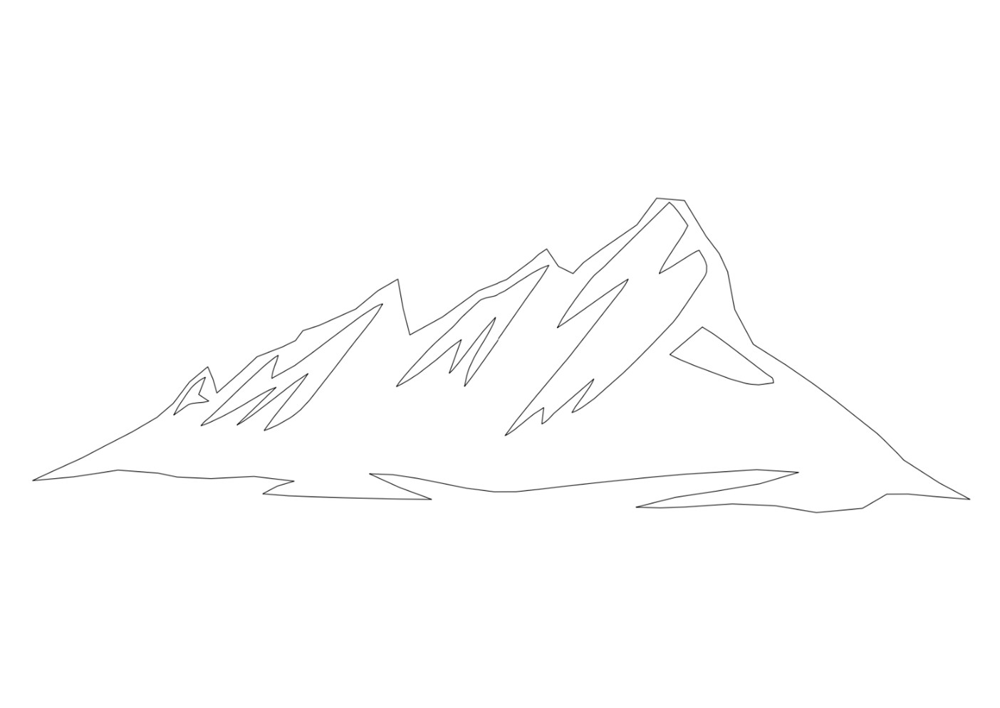
Figure (1)
As the focal point of my project is the flat iron mountain range, I needed to source a image that would clearly represent the silhouette of the mountain range without loosing the appearance of the three distinct flat iron faces. Shown above is a .DFX rendering of an image I sourced from shutterstock.com (1) which turned out to be the best option when taking into consideration keeping my overall minimalist nature aesthetic while still being able to laser cut without issue.
In order to make this cutout come to life I have placed the individually addressable WS2812B LED lights along the lower back side at an angle approximately 90 degrees from the face of the acrylic in order to direct the lights upward as to create the most natural looking backsplash effect behind the piece. Accordingly, I needed to not wash out the LED lights by being to close or to far from the wall. To fix this I printed out spacers that when affixed to the back of this piece create the perfect distance for the lights to shine as intended. These spacers also serve as the mounting mechanism for my mountains.
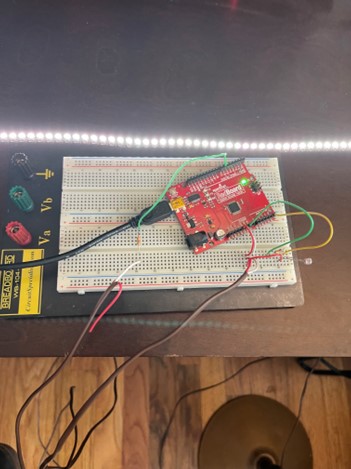
Figure (2)
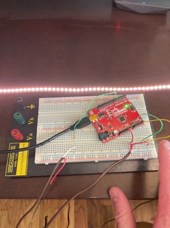
Figure (3)
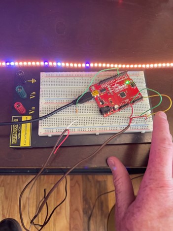
Figure (4)
As I am still waiting to mount the completed project on my wall, I have include the following images above which demonstrate the transition that occurs when the photoresistor detects different levels of light. The first image Figure (2) represents normal daylight (Approximately 3000k), the second image Figure (3) represents the transition to sunset colors, and finally the last image Figure (4) represents what happens when the photo resistor detects it is dark outside. The unique part about the last setting is that I have the code set up so that the orange sunset color fades away by having random LEDs light up with white and purple until it fully populates over the orange sunset color.
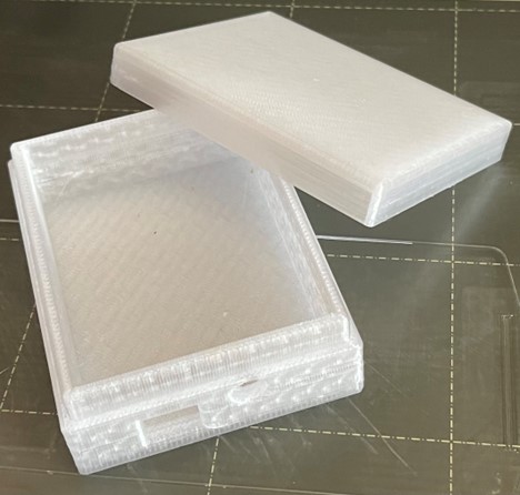
Figure (5)
With all the laser cutting, coding, and wiring complete, I moved forward with the fit and finish aspect of my project. As seen above in Figure (5), I designed a CAD model and then 3D-printed out a box that encloses my RedBoard and subsequent wiring. This part is neatly tucked away on my livingroom floor as to make the piece look as natural as possible without the unnecessary amount of electronics trying to all fit behind the flat iron silhouette.
Although I do have a successfully cut out acrylic flat iron mountain range, I am not as happy as I would like with its size. As such, I hope to be able to source a piece of 1/8″ thick by 24″X30″ piece of MDF wood which I will also laser cut providing me with a larger size for my finalized design. I hope you enjoyed learning about my project, thank you for reading!
Works Cited
(1) Shock, S. (2023). Flatirons mountains: Over 20 royalty-free licensable stock illustrations & Drawings. Shutterstock. https://www.shutterstock.com/search/flatirons-mountains?image_type=illustration
2 Comments. Leave new
Hi Ari, thankyou for the positive feedback, I plan to put the photoresistor in my windowsill as to provide the most accurate reading of true daylight coming from outside. Also I am going to hardwire it to the breadboard that will be located in my PCB box.
Hi John, this is a very cool project! Where will you put the photoresistor detector? And how will this be connected to the RedBoard? Overall I really like this idea and think it will look very nice when you’re done with it!