

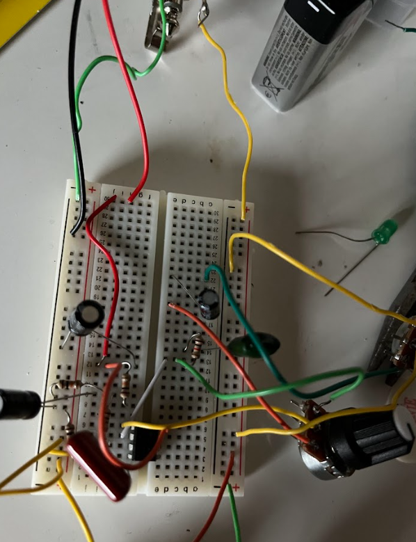
When I was going to make the semester project I first had to brainstorm what I wanted to make. I eventually settled with a overdrive guitar pedal because it is a product I have always wanted to do and I knew the circuitry would be in my level of circuit knowledge I had accumulated from school. After some initial circuit research, I needed to design and test my overdrive circuit. To do this, I needed certain sized electrical parts to make the circuit function properly. Using Amazon, I was able to source all the electrical components I didn’t already have from my school electronics kit. These components include various capacitors, op amp, mono jack, footswitch, and potentiometers. I then went onto circuit design. In this faze I built out my circuit on a breadboard hooking it to a 9V battery for power source and directly to my guitar and amp for sound input and output. This ended up being a fantastic idea as I could quickly and easily change my circuit design as I was testing to ensure that all kinks are worked out. This aspect was very important as getting electrical signals that translate into sound to work out correctly with minimal noise interference was somewhat complicated. After I was able to verify that my circuit ran exactly as intended on the breadboard I did my breadboard test. The test was basically me playing my guitar through the breadboard circuit and switching to overdrive and normal tone.
(Video: IMG_3248 (1))

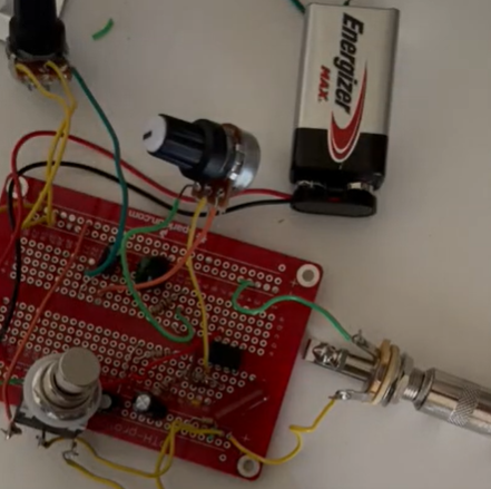
After the overdrive and normal tone was confirmed to be working on the breadboard circuit I obtained a solderable breadboard. The solderable breadboard is a PCB that has the exact same circuit layout as a normal breadboard. This way my circuit was easily translated onto the solderable breadboard PCB component by component and all soldered into place. This step requires a lot of patience as soldering connections well and exactly in the right spot is something I had done before but not required to do frequently in the past four years at CU. Once all the circuit components were soldered into the PCB, I went back home and performed the final circuit test. Much like the breadboard circuit test, the final circuit test had my circuit plugged into battery power as well as guitar to amp signal input and output. During the test, it took me a while to work out that there were minor connection problems in my circuit. I addressed these connections with solder accordingly and tested and re-tested until the pedal circuit functioned as intended.
At this stage, all that needed to be done was to machine the box that would hold the circuit. My machining steps were simple as I had to cut five different holes on the surfaces on the box. I drilled these holes with low precision on a drill press at I knew the mono jacks, potentiometers, and footswitch would be fastened into the holes by a nut so no threading was needed. The face of the box was then inserted into a laser cutter and programmed to laser etch the words “Volume”, “Gain”, and “OverDrive” in imprecise positions. From here, I put the circuit in the box, fastened all necessary hardware, and had a working Overdrive pedal.
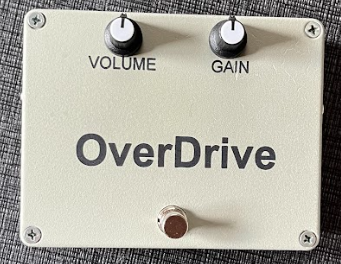
In conclusion, the pedal mostly functions as intended. I made an aesthetic change mid-way through the project when I switched from a polycarbonate box to an aluminum box. However, This switch was necessary for the integrity of my pedal. I wish I had taken more time to design a custom PCB rather than using a solderable breadboard since it was easy to get lost at crowded pin callouts. For now, I will be using my pedal since I proved it works with my amp. Future work might include trying to better the circuit so it plays with less noise.