
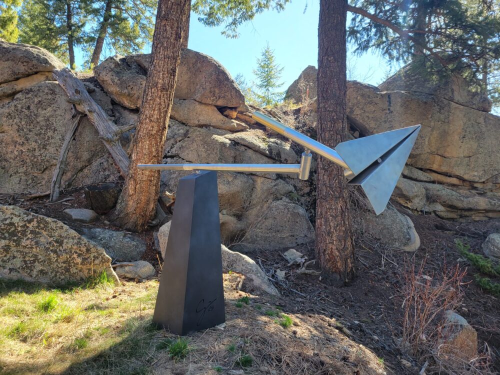
 As one can imagine, this was quite a large project and the “how” was the most difficult piece. I had made other sculptures before, many of similar size, but I had never made one that moved with such necessity for precision. Because the sculpture relies on balance to move gracefully, I needed to make each component nearly identical to the CAD as well as find the balance points of each section after manufacturing.
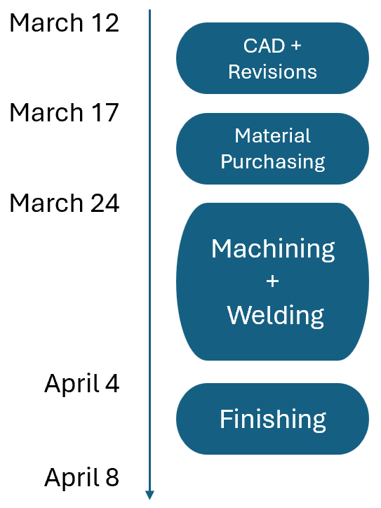
This manufacturing for this project actually happened in two stages. The first stage was the heavy manufacturing: when all of the large components were cut and welded, and the second stage was assembly and balance. The machining and welding were all done over spring break so I was able to spend up to 8 hours each day in the shop working on this project alone.
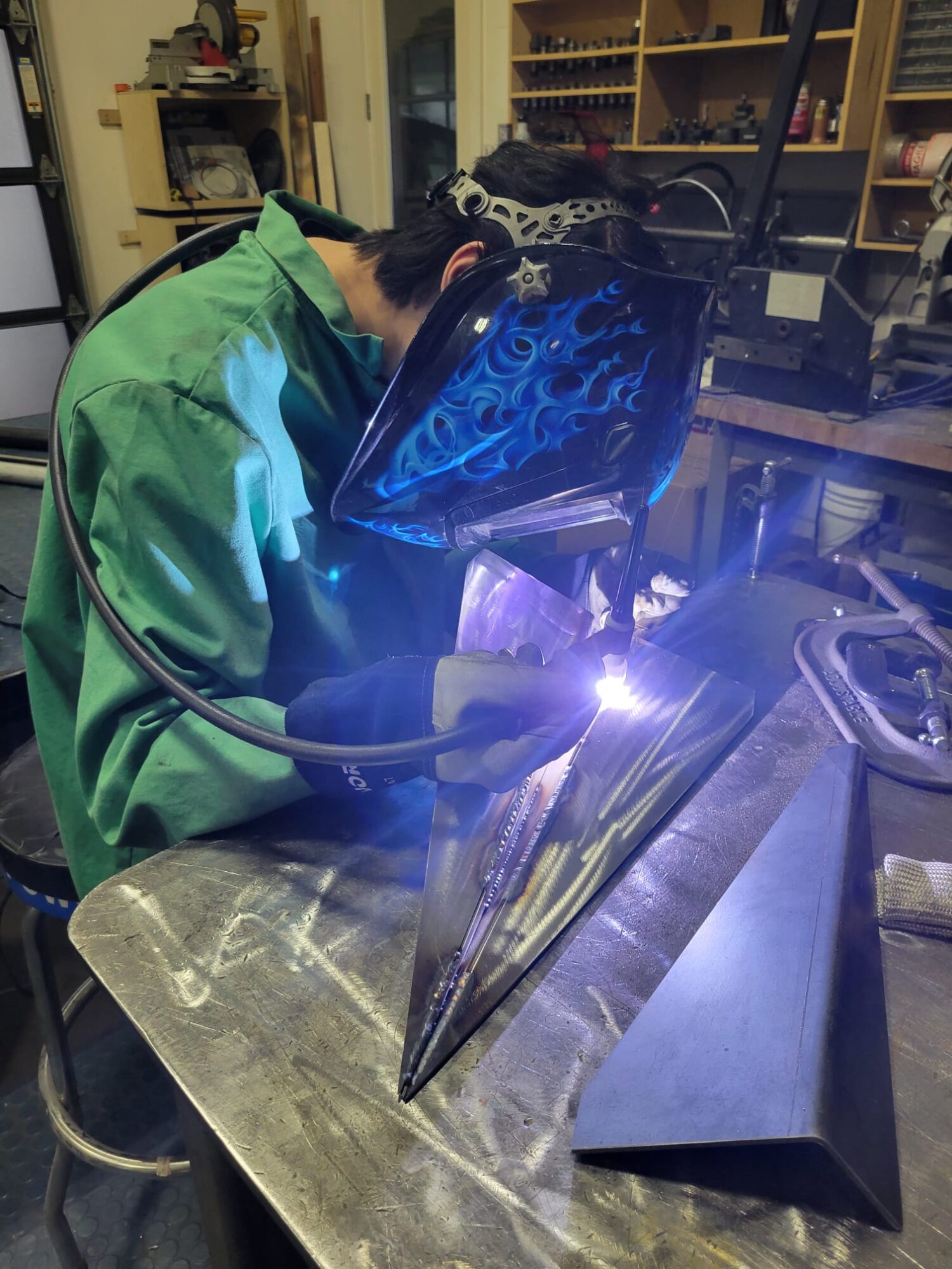
The largest hurdle for this project was the was welding. There are four different materials used in this sculpture, and of those, three had welded components. The mild steel was simple to weld as this is the most common type of welding and I had over 100 hours of experience of TIG welding mild steel. Before this project, I had never TIG welded stainless or aluminum, but I had used a spool gun before – an easier method that is not as clean – so I had a backup. Luckily, with some practice and experimenting with settings, I was able to learn how to TIG both of these materials.

The plane was made with stainless steel for its appearance and weather resistance, while the rest of the sculpture is mostly aluminum. These two materials are notoriously difficult to weld, so it did take some practice to get it right, but in the end I was able to get results I was satisfied with.
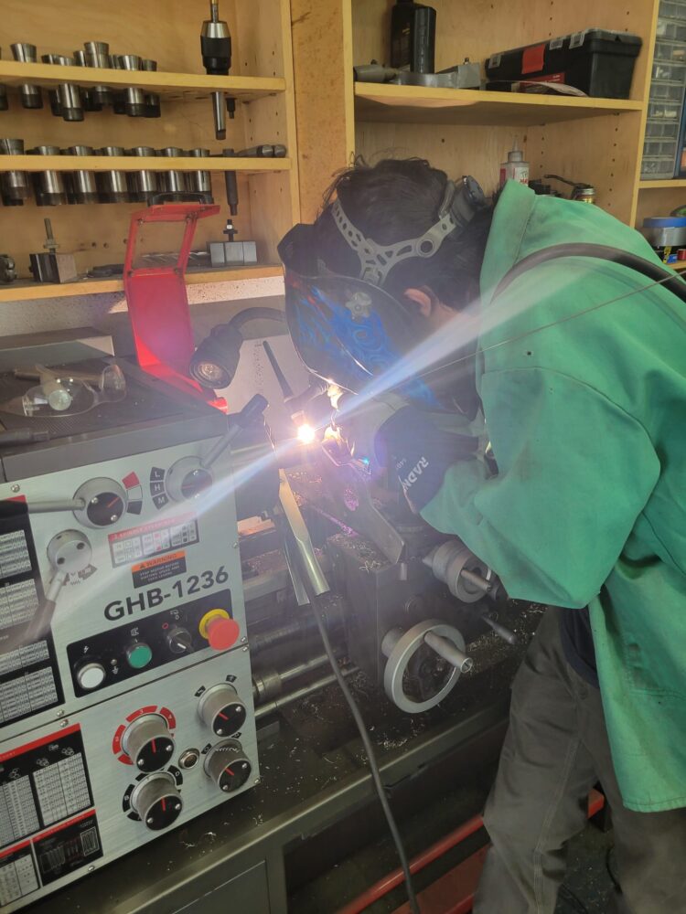
For some of the components, when welding on a round surface, it was easier to keep my torch in one position so I used the chuck in the lathe to allow me to slowly rotate the part as I welded. This allowed me to keep a consistent angle on the workpiece which resulted in a more consistent, better quality weld.
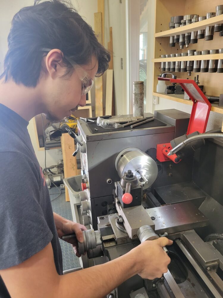
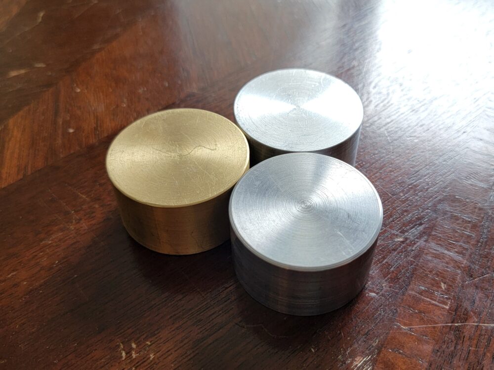
The components of the bearing housings required precision lathe work so I also had to learn how to design and manufacture higher precision parts than I previously had experience with. These components were important to manufacture well because they determined how well the final sculpture would be able to move in the wind.
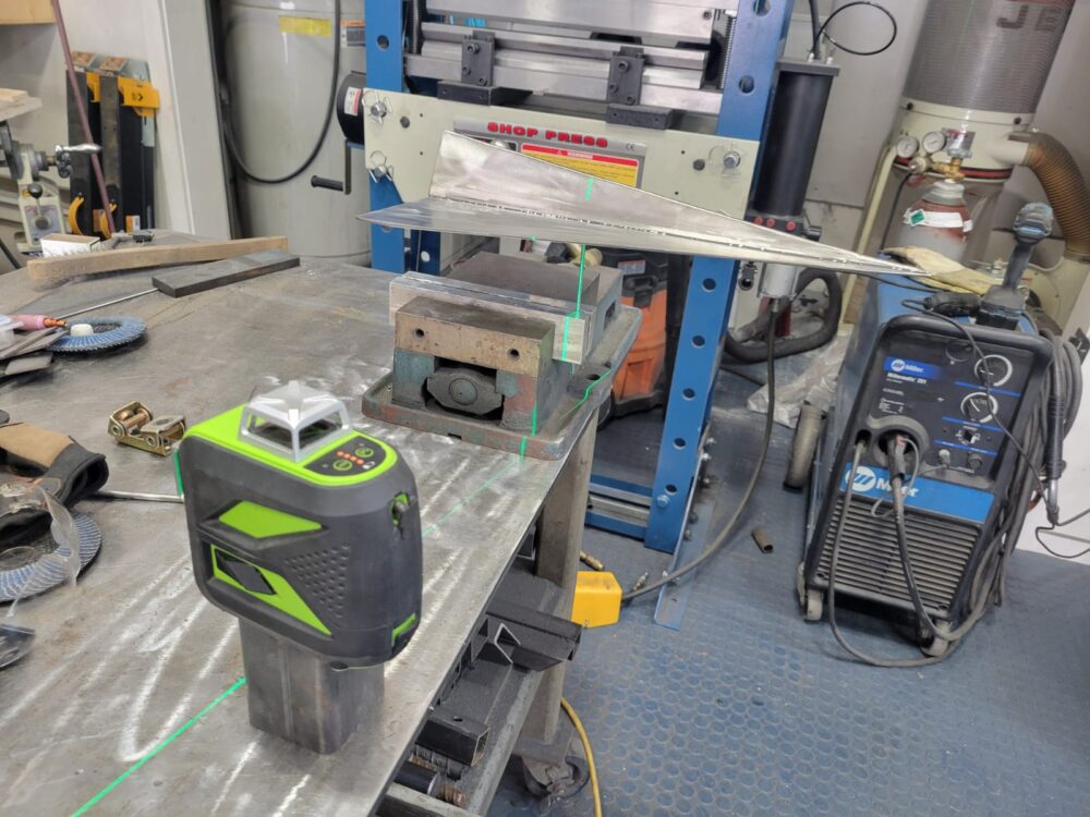
The balancing process was tedious. For the plane, I used a sharp rod to pinpoint the center of mass while balancing upside down. In order to transfer this point to the position where I would be drilling a hole, I had to use a laser level that creates a vertical line and align that with the rod where the plane was balancing. I was then able to add a fitting to the plane to accept the rotating shaft from the bearing housing.
1 Comment. Leave new
HI Sam,
This project looks really great, and the welds looks very clean on the connection points. My question is, are their any balance issues with this? How did you manage the center of mass to make sure this project doesn’t tip over?