
Project Overview:
For my final project, I will be designing a PCB Lamp. This lamp will be constructed using PCBs, generally a very unique building material.
Some of you may recall from my previous posts, I was planning to work on a completely different project. Originally, I opted to design and manufacture a dual purpose table bench. Purpose number 1 is to be a bench, however, upon flipping it over, it would convert into a mini indoor slackline. I love this idea, and still love it, and would like to attempt it in the future at some point. The main reason I opted to switch from that project to this new PCB project were logistics of moving the bench.
I am still unsure where exactly I will end up by the end of the summer. If I end up moving somewhere where miles and miles are required, transporting a bench made of mostly steel and a slack slab would prove largely difficult.
The Aesthetic: PCBs
I feel that this aesthetic is one of the few where the material drives the aesthetic, and not the other way around. Generally an aesthetic is not exclusive to any one material, however, when coming up with this idea, I wanted to be able to accentuate the key characteristics of a PCB. This was done by backlighting the PCBs in order to create a unique style of lamp.
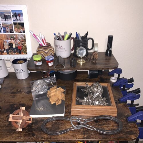
Additionally, I thought of this aesthetic due to the fact that I knew this would be a standout piece. Because PCBs are generally closed off from the world, they spark a lot of interest when people are actually able to see, feel, and interact with them. Art pieces which challenge the norm or follow unique styles will also spark this unique interest. On my desk in my room, I like to keep various trinkets that people can fiddle with, talk about, and be puzzled by. Notable items are a horseshoe puzzle and magnetic sculpture toy. These are often fun conversation starters and ways to pique new interest. This lamp would be a new fun addition to the collection by adding a visually striking piece.
Project Inspiration
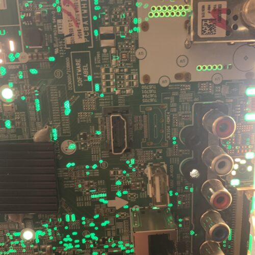
I came across this idea when I stumbled across an image of a backlit PCB shown below:

Previous Ideas
Before settling on the PCB lamp, I worked through a few alternate ideas, both of which were clocks, along the same aesthetic.
The first design below, is a clock which utilizes a PCB as the face and a flexible PCB around the outside to make it a circular clock.
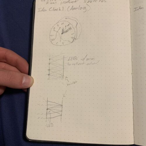
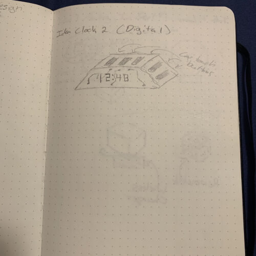
This next design utilized PCBs to create a clock again. This idea was to be a digital clock with standard functions including an alarm.
After considering those two ideas, I decided to continue forward with the PCB lamp idea instead. There were a few reasons for this decision. The first is that I already designed a clock during the upcycle project. The second reason is that I felt a lamp would be an excellent addition to my room.
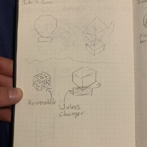
Initial Sketches
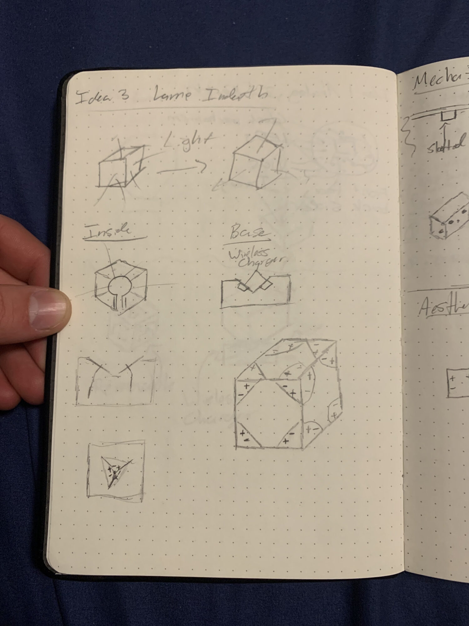
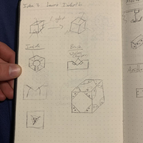
At this point, I have started sketching design ideas. These show the general ideas for how the cube will come together, the mounting solution, and more.
The following image depicts one of my first sketches demonstrating what form I expect the lamp to take. Notably, I would like the lamp to be able to accept power through the outer faces of the PCB, however, all of the electronics will be internal. This brings out a case where ideally pogo pins, wireless charging, or another connectivity method would be implemented. On one of the sketches, pluses and minuses can be noted as well in order to denote how the polarities should align themselves on the lamp. By keeping it consistent, the lamp is able to be powered in any orientation.
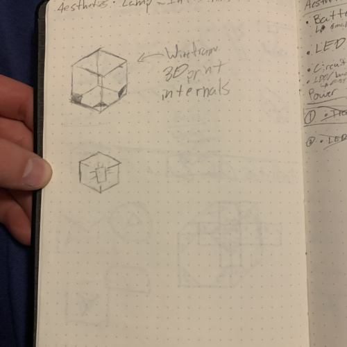
The image below shows the plan for wiring internally to ensure all panels are connected. On each PCB, all four sides are connected, however, connections need to be extended to adjacent panels. The simplest way to figure out which sides to connect is to lay the cube out unfolded and make it such that each cube is held on by wires. Once each cube is attached by wires, it means it should be in the proper orientation.
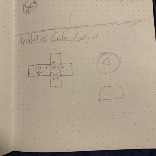
This final sketch shows two different ideas. The top ideas depict other shapes, however, I determined that cube would be the proper shape to make it all work properly.
Conclusion
Overall, I am very excited for this project. Based on my initial testing, I think the aesthetic and the functionality will work out just fine by the end of the project. There has been a lot of work put into the project before spring break in order to help with timeline issues.
1 Comment. Leave new
Hi Ian, I think your whole project is super cool! I think it would look great somehow hanging from the ceiling. I didn’t know how PCBs glow when backlit and it looks really cool. I’m excited to see how this ends up!