
Inspiration
I got the inspiration for this project as I was working on the Upcycling project. Halfway through, I got the idea of making a desk lamp out of an old engine valve cover. Since I was already well into my Upcycling project, I decided to make the lamp as the final project. 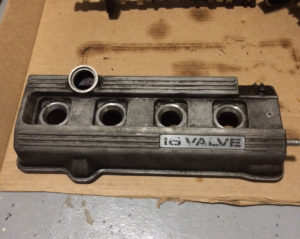
After thinking about the logistics of this lamp, I decided the scope would be too simple. I wanted to give it a more dynamic function to this lamp. Then, I remembered a project my friend did as a senior design a few years ago. She made a drum that would measure your heart rate and would beat at the same rate. I thought it might be cool to do the same with my lamp, and my project scope was decided. I would use red LEDs to go with the theme of the heart.
Planning
I decided to use a simple PLC to control the on/off state of the lamp. Since I have never used Arduino before, I thought this might be a good time to learn. The aesthetic for this lamp would be called “Industrial Chic Automotive.” Doing a quick Google search of “automotive furniture” yields a lot of cool things others have made from upcycled car parts. My aim was to create something similar, with a little more dynamic function.
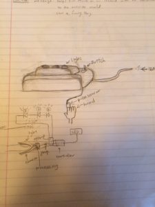
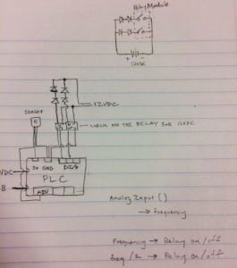
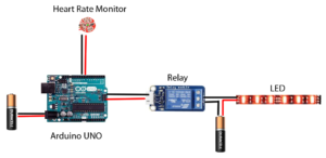
I sketched out some initial concepts. I wanted the LEDs to be brighter than what an Arduino typically powers, so I would need to use relays. The Arduino digital outputs would control the relay, which in turn would control the on/off state of the LEDs. This meant that I would also need two separate sources of power.
Procurement
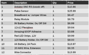
I put together the final bill of material and purchased everything through Amazon. This was approximately 2 weeks before the presentation week, so their 2 day free shipping really helped out.
Receiving
After the parts arrived, the first action was quality assurance. I tested each item to make sure they’re functional so that if I had to reorder things, I would have plenty of time. I discovered that 2 of the 4 LED strips didn’t work properly. I opened up the strips to discover loose connections. I resoldered the connections, which seemed to fix the problem. I also discovered that the 9V battery case was not working. There was a loose connection and the battery wasn’t making contact with the lead. After bending some metal connections, I was able to get it working.
Functional Test
Before doing the mechanical assembly, I wanted to wire everything up and make sure that things will function as I had imagined them to. I hooked up the Arduino board, the relays, and the pulse sensor. I found Arduino code from the website that makes the pulse sensor to control a digital output based on the input of the pulse sensor.
I ran into a minor issue related to the wetting voltage of the relays. I didn’t realize the digital outputs of Arduino do not provide a wetting voltage, so I had to wire a 5V wetting voltage to the relays. Since I was already using the 5V for the pulse sensor (pulse sensors were not loop-powered), I had to split the 5V power into a parallel circuit using a breadboard, and hoped that the output current was enough to power both devices (it was).
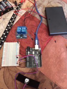
In this video, the relay can be seen clicking at the same rate as my heartbeat.
https://www.dropbox.com/s/gn0mf4k5v8ceoo6/Video%20Apr%2011%2C%2010%2048%2052%20PM.mov?dl=0
I didn’t hook up the LEDs to the relay, but I knew if the relays were clicking, the LEDs wouldn’t be a problem.
Final Assembly
Once I verified that everything would work according to plan, I first cut a piece of plexiglass using a miter saw. I’m not sure if the blade was supposed to cut plexiglass because the plastic started to melt from the friction of the blade and would spit hot plastic everywhere. Either way, it got the job done.
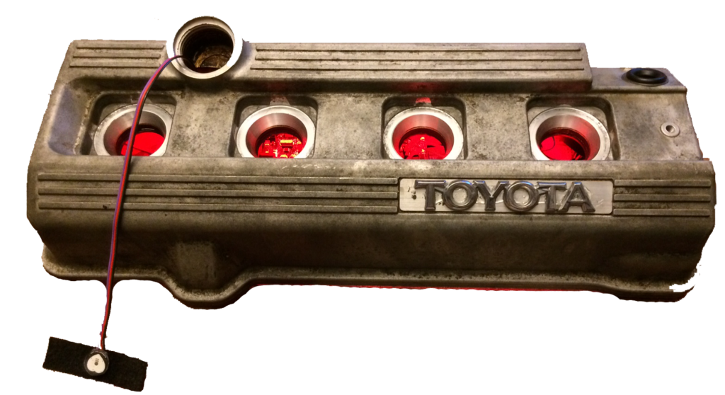
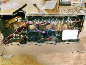
The Arduino board, the relays, and the breadboard were mounted to the plexiglass using rubber cement. The LED strips were mounted to the top of the valve cover. Once everything dried, the plexiglass with the electronics was mounted to the valve cover, as shown below.
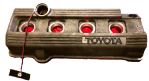
Once they dried together, I flipped it over and mounted the TOYOTA emblem off of the car to finish it off.
The final schematic:
Acknowledgement:
First of all, I want to thank my co-worker that got in a car accident and donated his car to my friend (don’t worry, he was perfectly safe). I also want to thank my friend for helping me remove the valve cover, and for letting me use his tools throughout this project. Finally, I want to give special thanks to my teammates, Alex and Jian for helping me with many great ideas for this project.
The Arduino code I used was written by Joel Murphy and Yury Gitman.