
When thinking about what I wanted for my final project, my first overarching idea was to create a memento from CU that I could bring home, show off to my friends, and have for years. My next lightbulb idea under the CU memento theme came from a mechanically programmed horse I found on YouTube, as seen in the image below. I thought I could replicate this idea but for a buffalo instead.

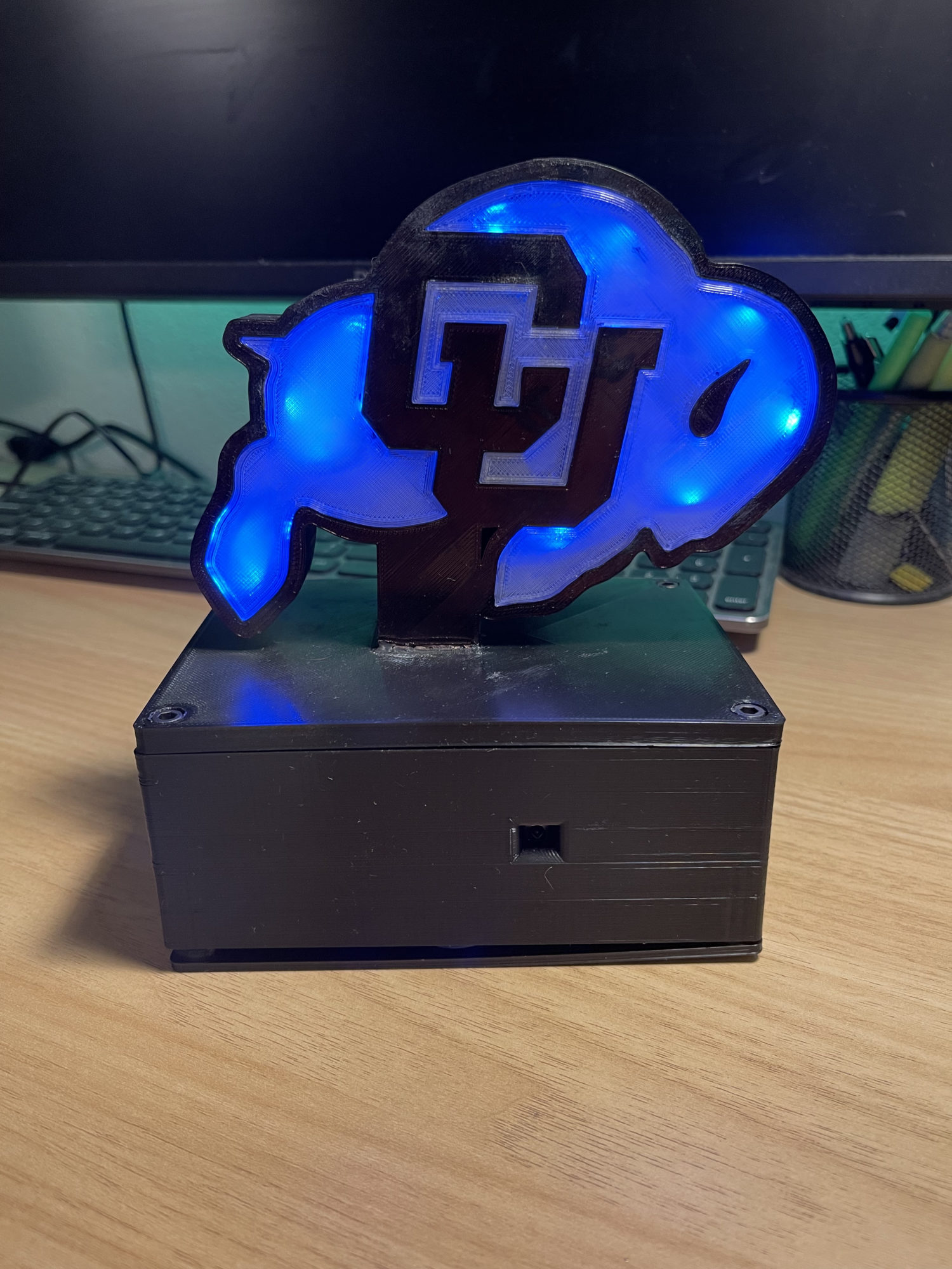
As I started working on the CAD in SolidWorks, I realized how much work and the complexity of the joints this project is. I spent two hours working on the back leg assembly and did not get any substantial work done that was up to my standard. So I decided to pivot to making a display piece that was electronically dynamic instead of mechanically dynamic. As I rummaged through my electronics bin, I found a couple of parts that sparked a more clear-cut idea. These parts were an Arduino Uno, an individually addressable light strip, an IR receiver, and a remote. From these items, I came up with the idea of creating a buffalo lit up from the inside with a black border and transparent diffuser to help spread the light throughout the body.
![]()
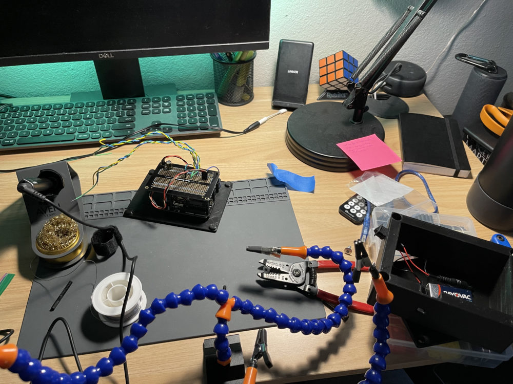
I spent much of the next two nights CADing, testing electronics, and soldering everything together. Some specifications I set while I was designing were that it had to be free-standing where it didn’t need to be connected to an outlet, It needed to be visually unobtrusive where it doesn’t stick out like a sore thumb, and that strong enough to move from place to place as I move away after graduation. From there, I could print all the parts at home out of black PLA and the transparent faceplate out of clear TPU, with a total print time of about 39 hours. Next, I superglued metal thread inserts and the CU Buffalo faceplate to the top of the box and ran the LEDs along the inner side and wiring through the base.
One of the more demanding challenges I faced was gluing all the parts together on the CU Buffalo main plate as I first had to glue one transparent side, the LEDs, and the other side. But the other transparent side didn’t fit perfectly, so I had to wedge it in while getting super glue all over my hands, which took a long time to get off.
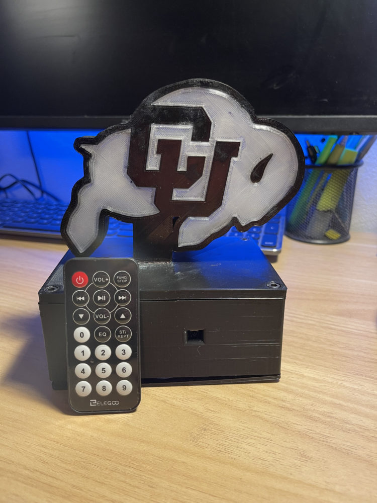
As I am still coding the LEDs to be switchable with the press of a button, I am open to suggestions on any color or lighting schemes you have in mind. I currently have solid Red, Blue, and Green, and one that fades between those three colors.

Presentation Video:
CAD Files:
Buffalo (Zip file)
2 Comments. Leave new
Hayden,
I like that you transitioned from a mechanical dynamic to a electrical dynamic, the colors look great on this. Was there a different solution to sticking everything together besides glue?
Thanks for the comment, Peter! When designing the pieces to fit together, I only designed them with face-to-face tolerance so I could put glue in between those faces. Looking back, I think this was my downfall as some of the piece tolerances were too small, and the faces didn’t fit together right and causing it to be hard to glue. An alternative option I am considering is creating a lip that, once you push it into the lip, it just stays, like how a chapstick cap snap fits into place. This would allow me to limit or not even use glue at all.