

My final project of my brutalism water wheel overall went very well and the process ended up working out okay, considering a few hiccups that I faced.
To recap, below is a picture of my design timeline:
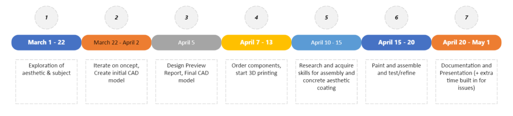
A few things happened at the end of my timeline that made it difficult to meet this. My 3D printing class got cancelled, so I had to last minute order my 3D printing parts through the Idea Forge and am very lucky to have been able to do this remotely and have them printed for me. I was also sent on an out-of-state work trip the week I was supposed to pick up and assemble all of my parts, so I had a big delay because of this. Even with this, I was able to get all of my 3D printed parts and assemble them with minimal issues albeit later than I was hoping for.
My design process started by using CAD in SolidWorks to come up with my initial design. After a few rough paper sketches, putting it in CAD helped me see how it would all fit together and the weight of the parts. At this point, I decided that my original idea of molding out of concrete would not be feasible because it would be extremely difficult to rotate at the scale of my project since it is a pretty big object. I also wanted it to be very blocky to meet my brutalism aesthetic, so there would have to a lot of concrete used and weight added just because of the aesthetic I chose as well. A picture of my CAD is shown below.
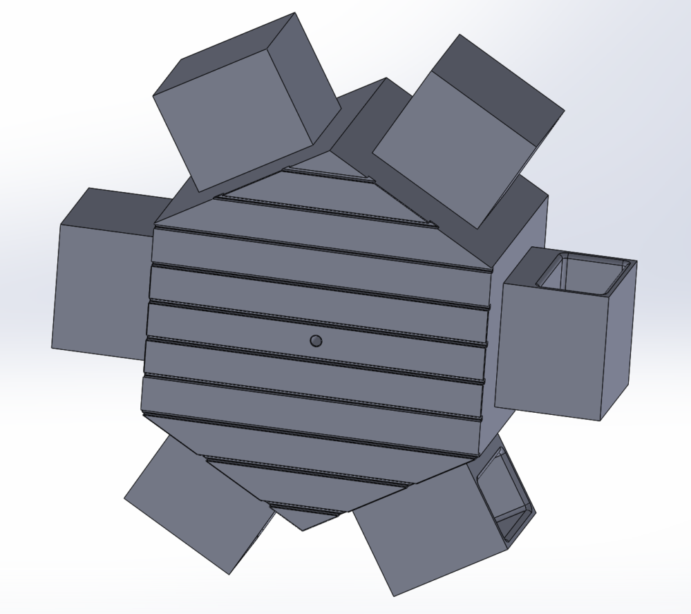
Because of this CAD analysis, I decided to shift and 3D print my parts to conserve weight and try to simulate concrete look by paint and textures after the fact. I originally signed up for a class locally since I do not live in Boulder in order to get access to the 3D printers at my work, but this got cancelled right before due to not enough people signing up. At this point, I decided my only option was to order them through the design lab in the Idea Forge. I printed them out of PLA and the scale of my parts are pretty big since just my base is 5x5x6 inches, so all 7 of my parts took 2.5 days to print and multiple printers running at the same time. I also used a 10% infill since this helped me reduce weight. I also used a metal shaft and two shaft collars on either end to constrict the rotation of the wheel a bit using friction and then the shaft is used to secure it to the koi pond I was planning for it at my parents house.
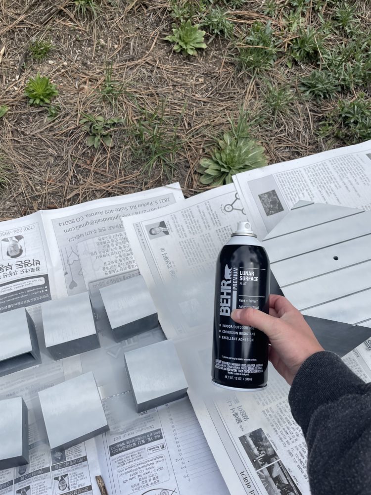
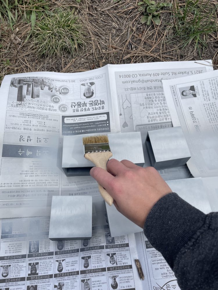
After I received my 3D printed parts and shaft components, I bought some flat/matte gray spray paint that I thought resembled a light concrete color. I wanted to choose a lighter concrete color as opposed to a darker one, so that it would stand-out a bit in my parents garden since the pond itself is from a black color and I didn’t want it to match too closely to that. While the spray paint was still wet, I used a rough paint brush to add texture to the blocks. It is hard to see from the pictures, but it has a rough and inconsistent texture that I think is fairly characteristic of concrete. I had to repeat this process a few time of painting and texturing to get the look I wanted. I used plastic bonder to then add the six water buckets to the sides and let that bond for a few hours.
Then, I added the shaft and shaft collar to the part. When the epoxy was bonded, I added a final coating of waterproof sealant since this is going in a space where it will be wet constantly and there are living animals. Below are a couple pictures of the final project.
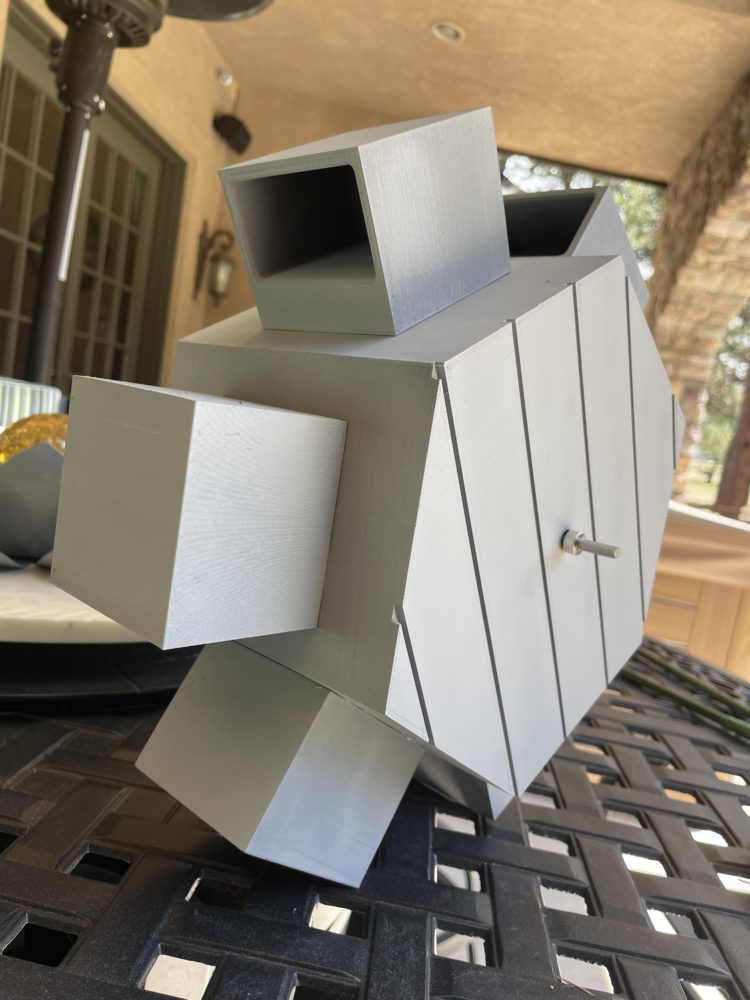
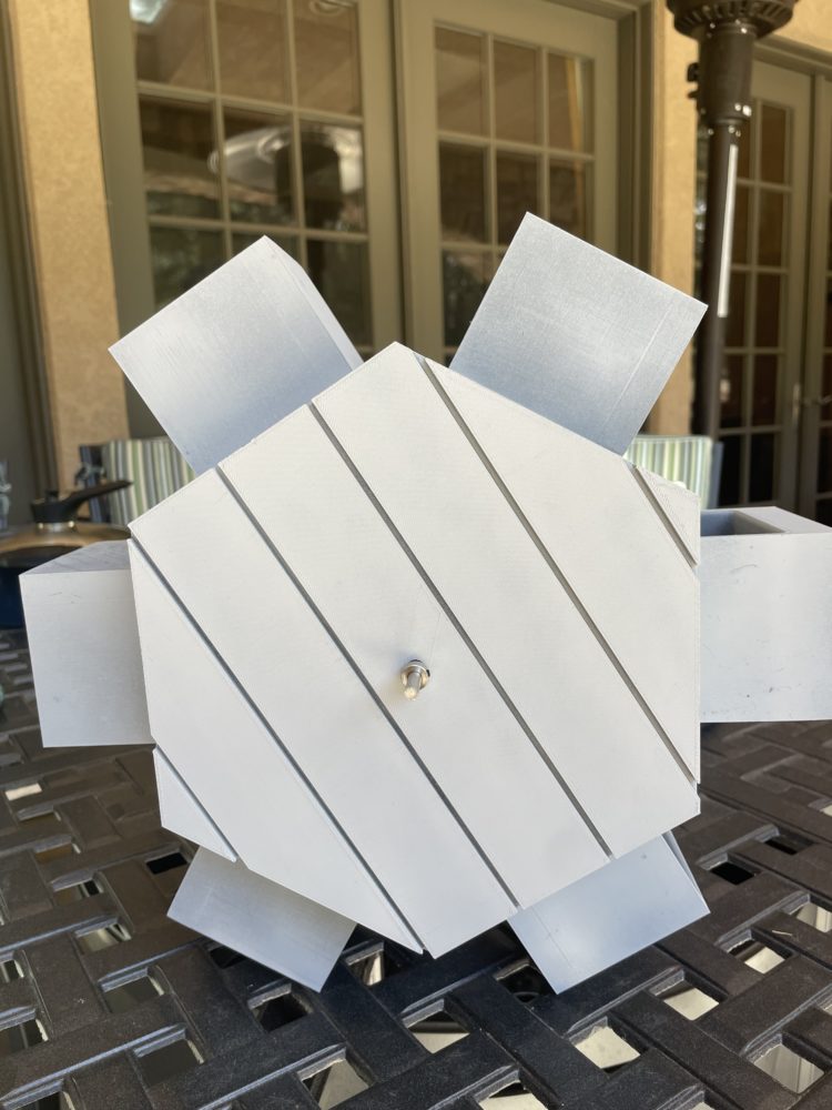
![]()
When I took it to my parents house in hopes of installing it underneath their goldfish pond, I found out that they hadn’t actually set up the pond for the summer time yet. The final installation, I will likely have to do in a couple weeks after the class is over, but I got the help of my family to hold my water wheel, so that I could test the speeds with the water hose and see how it would work. I was able to get a couple short videos to show the idea of my final project. These two videos show the water wheel running at two different speeds which accomplished my goals of being able to have adjustable speeds.
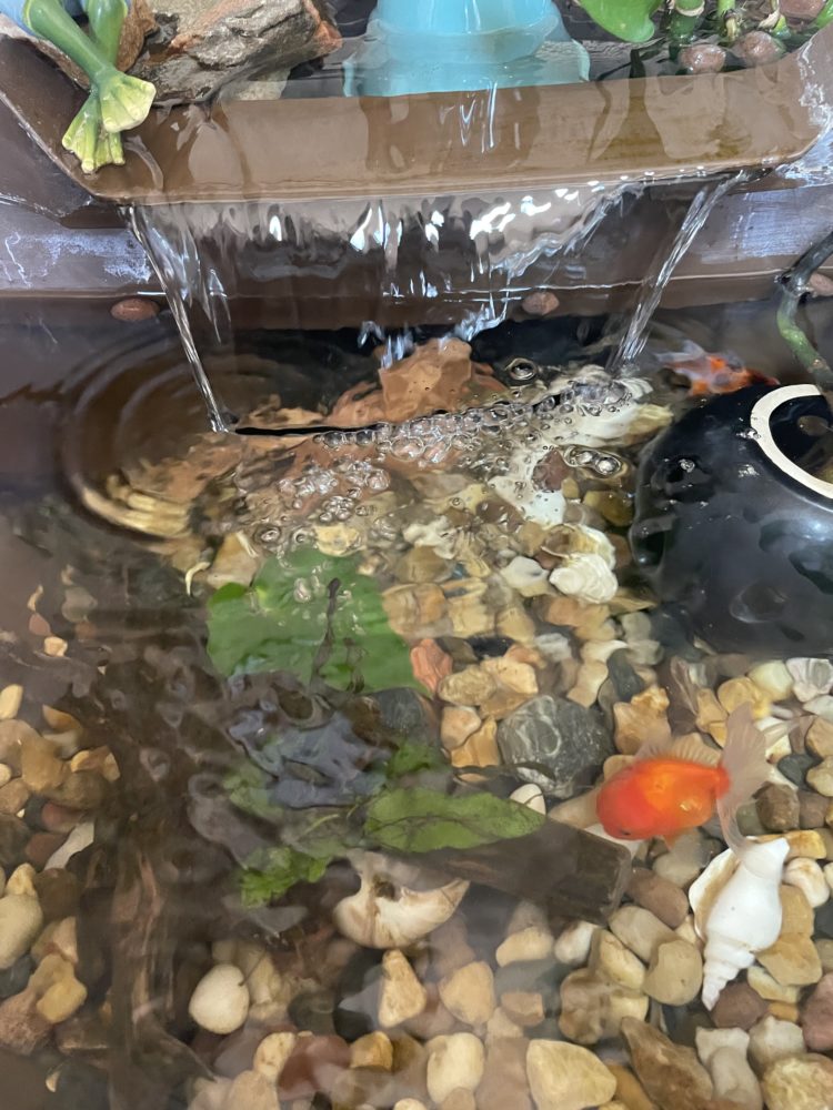
Overall, I am very happy project, but in the future I would have liked to change the process of adding texture to the parts and also the lines I added to my base since I think that gives it more of a wood feel instead of a concrete block feel. I may do a second iteration as I am waiting for the goldfish pond to be set up, but I am excited to add it as a dynamic aesthetic piece that will hopefully be peaceful to look at and listen to as the water falls onto it. For reference, this is a smaller goldfish pond at my parents house with the tiered waterfall that I would be trying to use as the water source for my project:
Here is a link to my final presentation, as well:
https://cuboulder.zoom.us/rec/share/eJyYxFHplYDyQS1cx9DR3S_njlqsf8PDjSMn4BubWdd9VYWrg6L_ljJYSNb1uJaV.WSOsR2Pc0aiqSrUu?startTime=1683140552000
Passcode: co^paDU4
1 Comment. Leave new
I really like how the end results of your project came out i think it will look really good in the pond.