
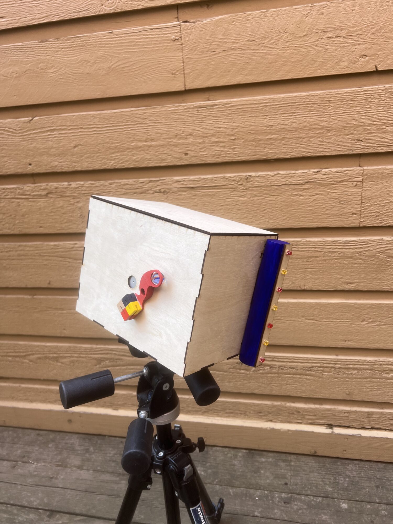
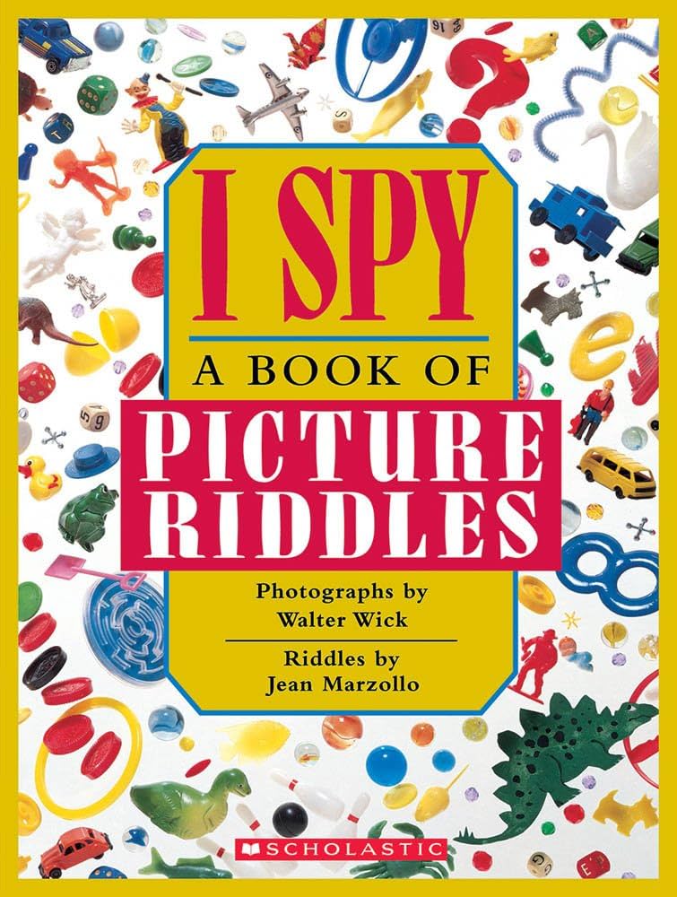
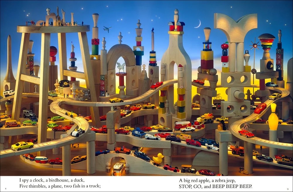
For my Aesthetics of Design final project, I made a large format pinhole camera in a toyshop aesthetic inspired by the iSpy books of the 1990s and 2000s.
Introduction:
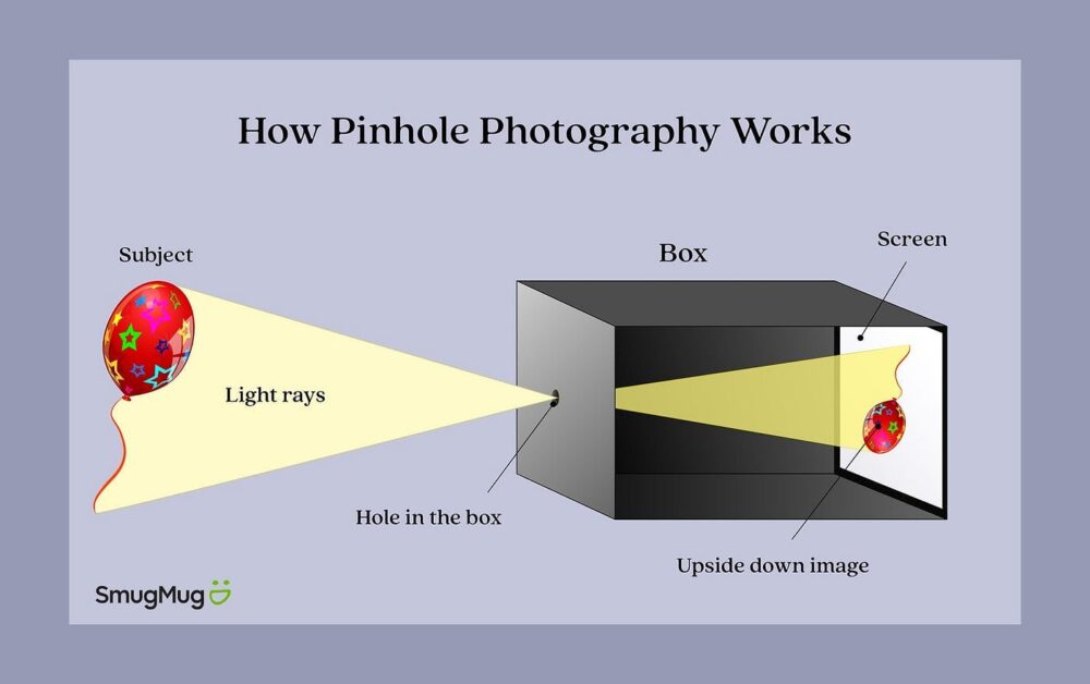
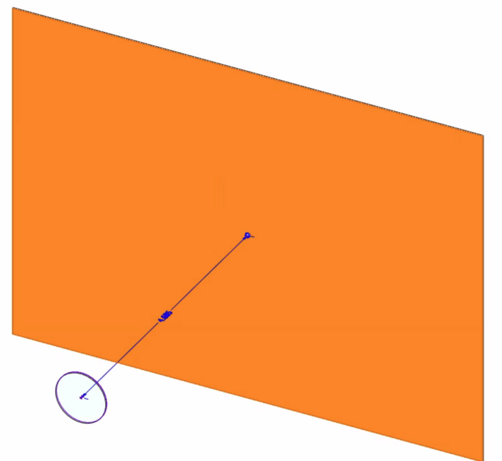
What is a pinhole camera? A pinhole camera is a very simple image making device that relies on the “camera obscura” effect. It is essentially a light-proof box with a very tiny hole in one side. This small hole, or aperture, lets a few light rays in that project an inverted image on the opposite wall of the box.
Design:
Functional features:
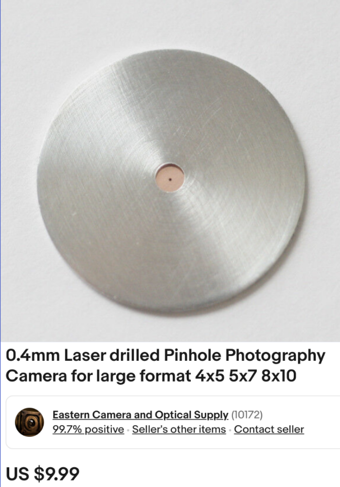
• 0.4mm pinhole
• Wooden camera body with focal distance sized around pinhole calculation
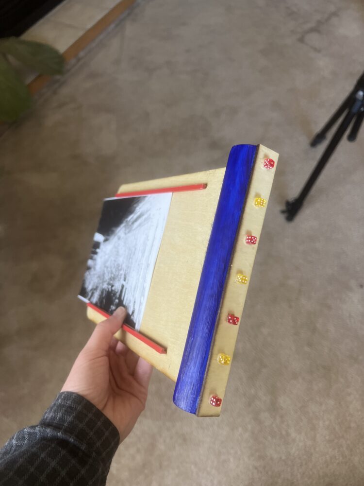
• Film slide that holds 5×7 photo paper and can be inserted to/removed from camera body
• Inside lined with black tape and felt to minimize excess light from hitting the photo paper
• 2 1/4-20 threaded inserts for attaching the pinhole camera to a tripod in both landscape and portrait orientation
Aesthetic features:
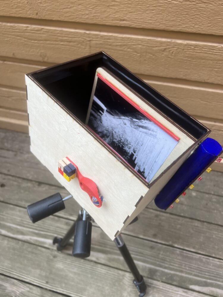
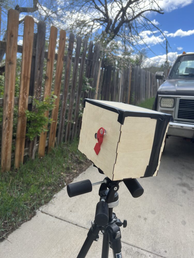
• A wooden camera body brought together with finger joints to evoke the wooden blocks and landscapes of the iSpy image
• Bright, primary colored accents through the film slide (red paper retainers and blue handle) and shutter
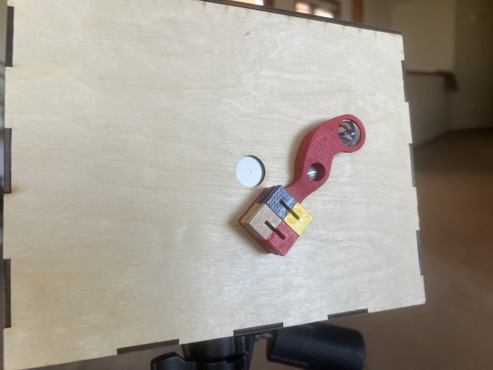
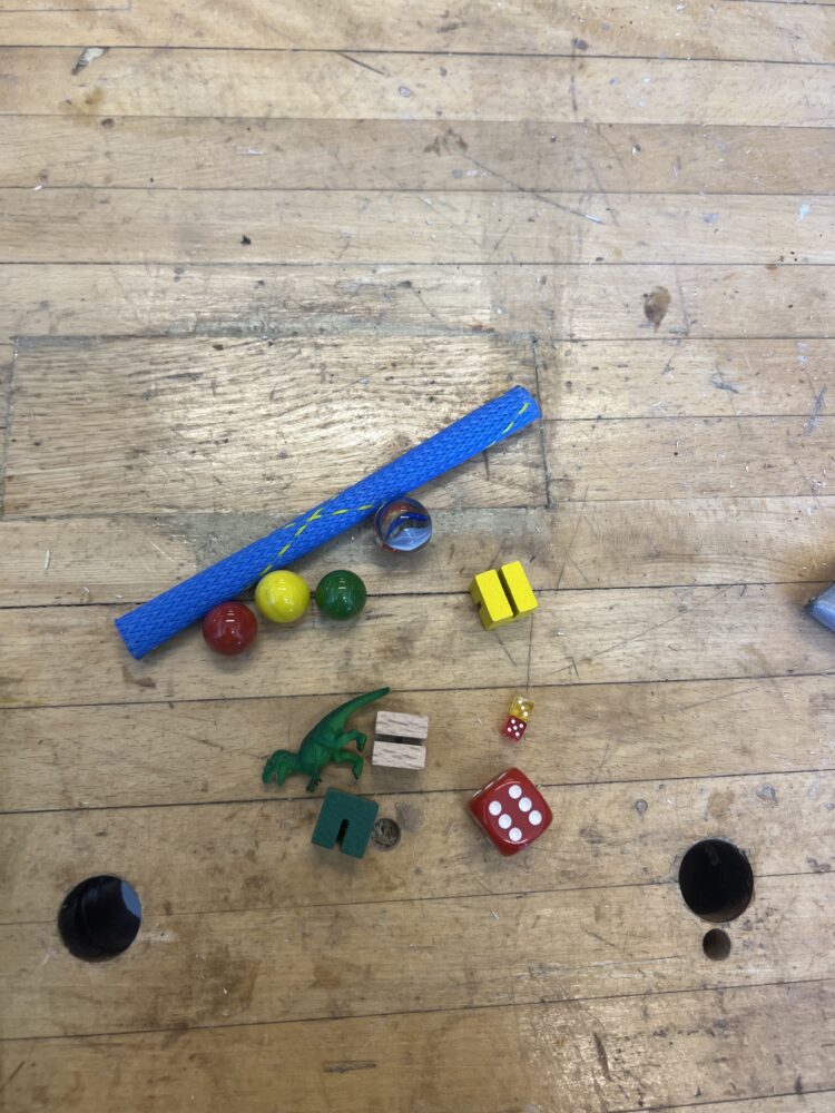
• Various toy decorations: tiny dice dotting the side of the film slide, wooden puzzle blocks (arranged to look like a set of eyes) and a marble that spins as the shutter moves
• A sense of whimsy through the sweeping lines of the shutter
Manufacturing Process:
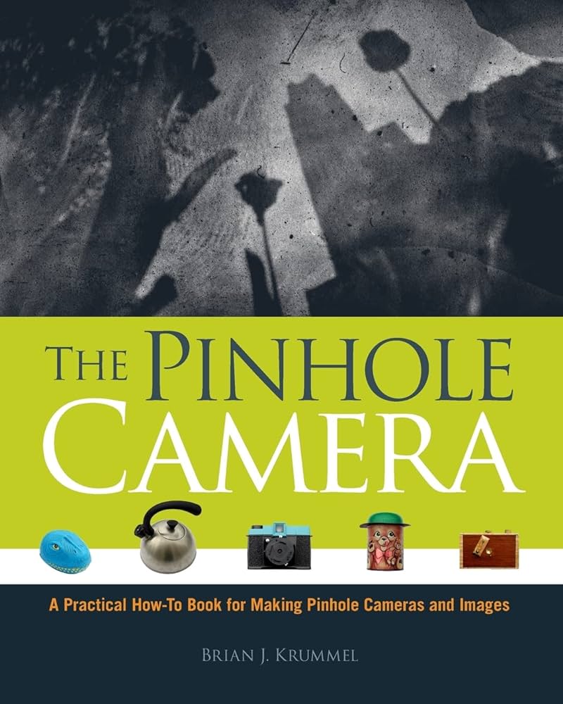
I began this process by heavily researching pinhole camera projects. There are a lot of useful hobbyist sites that have instructions on how to build them, and the math that goes into different camera dimensions [4-6]. The most helpful resource was The Pinhole Camera book by Brian J. Krummel [7]. It was essentially a compilation of all the information I had found on the online resources. I came across this book on Amazon and the CU Library system ordered it for me to use.
Then, I selected the components that would govern the rest of my pinhole camera design. I purchased a 0.4mm diameter pinhole from a camera supply company. Pinholes can be made out of any thin material like aluminum foil, but this $10 pinhole provided me with exact dimensions and a more robust disc that could be integrated into my camera body.
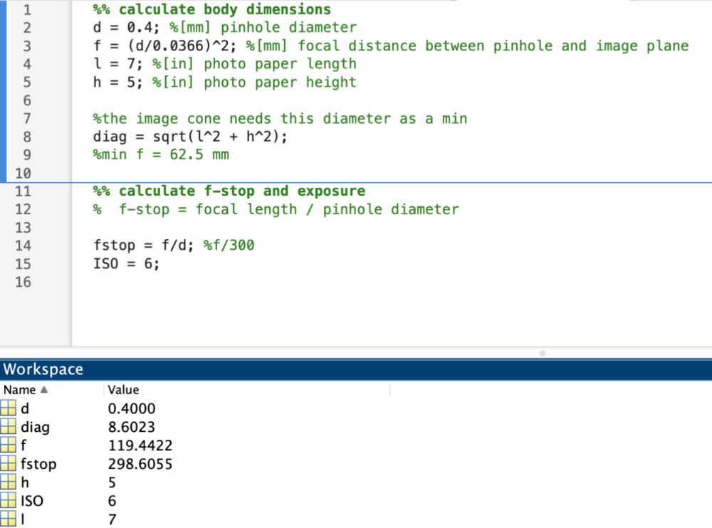
With these two selections I could start designing the rest of the camera body. I calculated the ideal distance between the pinhole and the photo paper which governed the dimensions of the camera body, and ensured that the projected image would cover the entire paper. I also calculated various qualities of the camera like the f-stop which would be utilized later to determine the exposure times. While these were simple calculations, I still utilized Matlab so I could easily play around with different variables to see their effects.
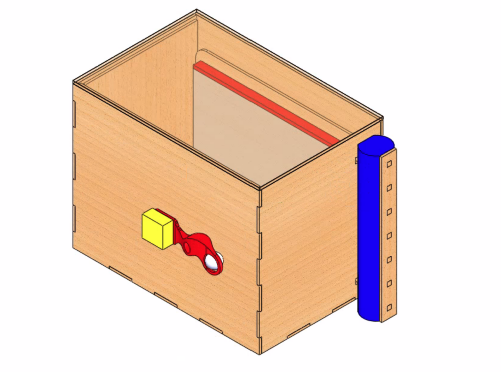
As I mentioned, knowing the focal distance between the pinhole image paper allowed me to design the rest of the camera. I utilized SolidWorks to set this dimension, build a box around the components, and get my desired internal dimensions. I could use these dimensions and the MakerCase website to easily get a box with finger joints and the respective DXF files for laser cutting. I also designed the slide handle, photo paper holders, and shutter in SolidWorks.
 Camera Body:
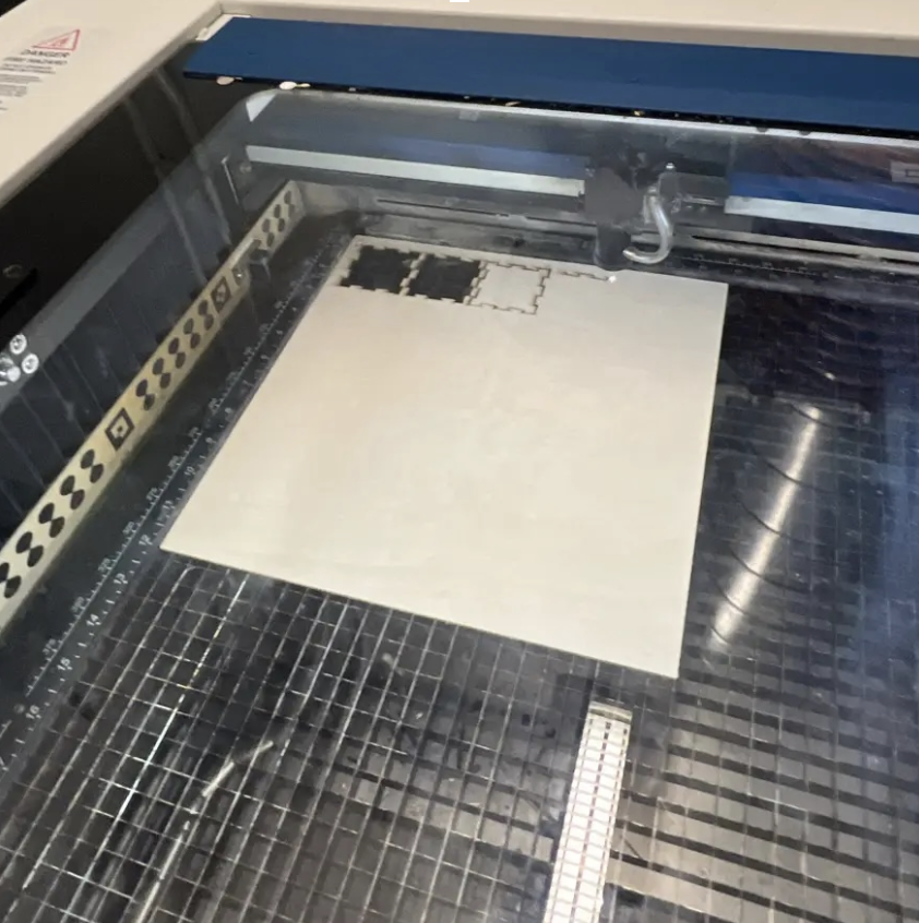
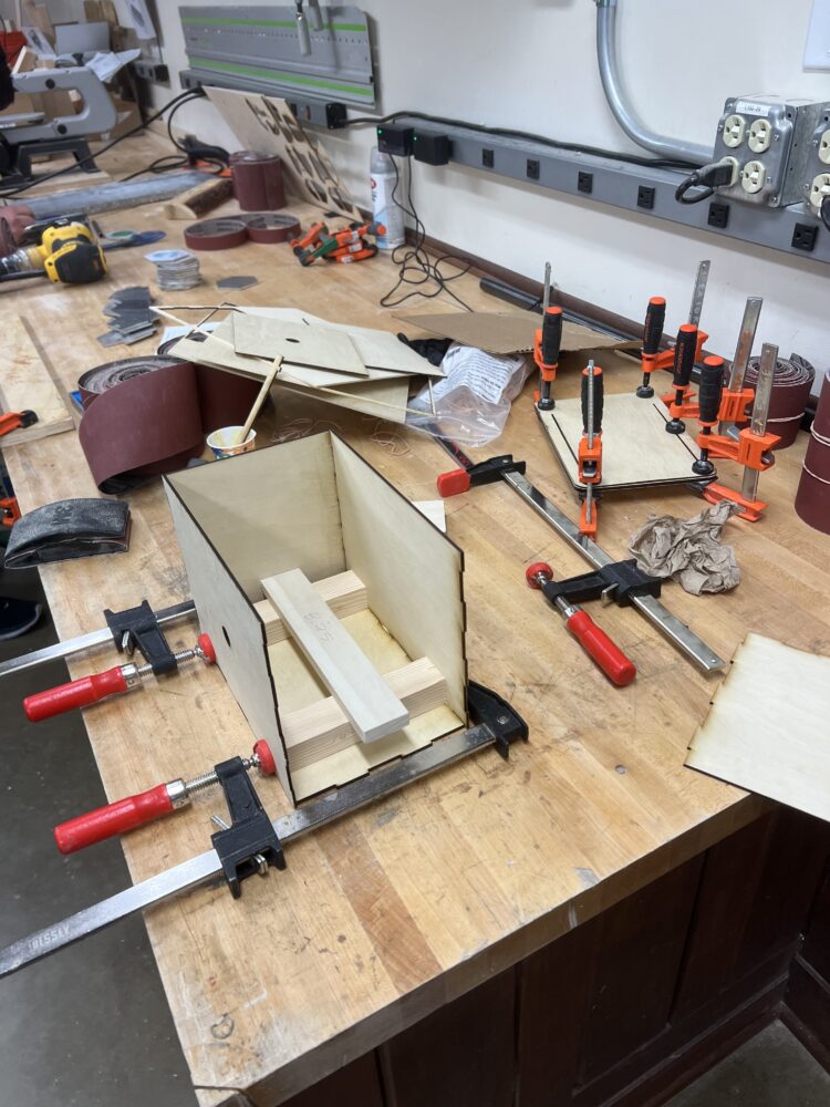
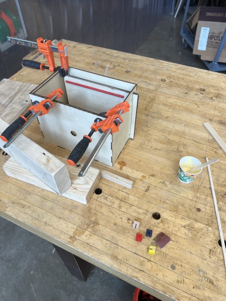
I laser cut 3mm sheets of Birch plywood sheets to make the walls of the camera body and the paper slide. This image shows a test cut I did to see if I would need to compensate for kerf in the final cuts . I then glued up the box, using scrap pieces cut to the internal dimensions to ensure the box was square. I glued a second sheet in areas I would be drilling into and in areas that I wanted channels (like a channel to hold the paper slide in place or the inset for the pinhole).
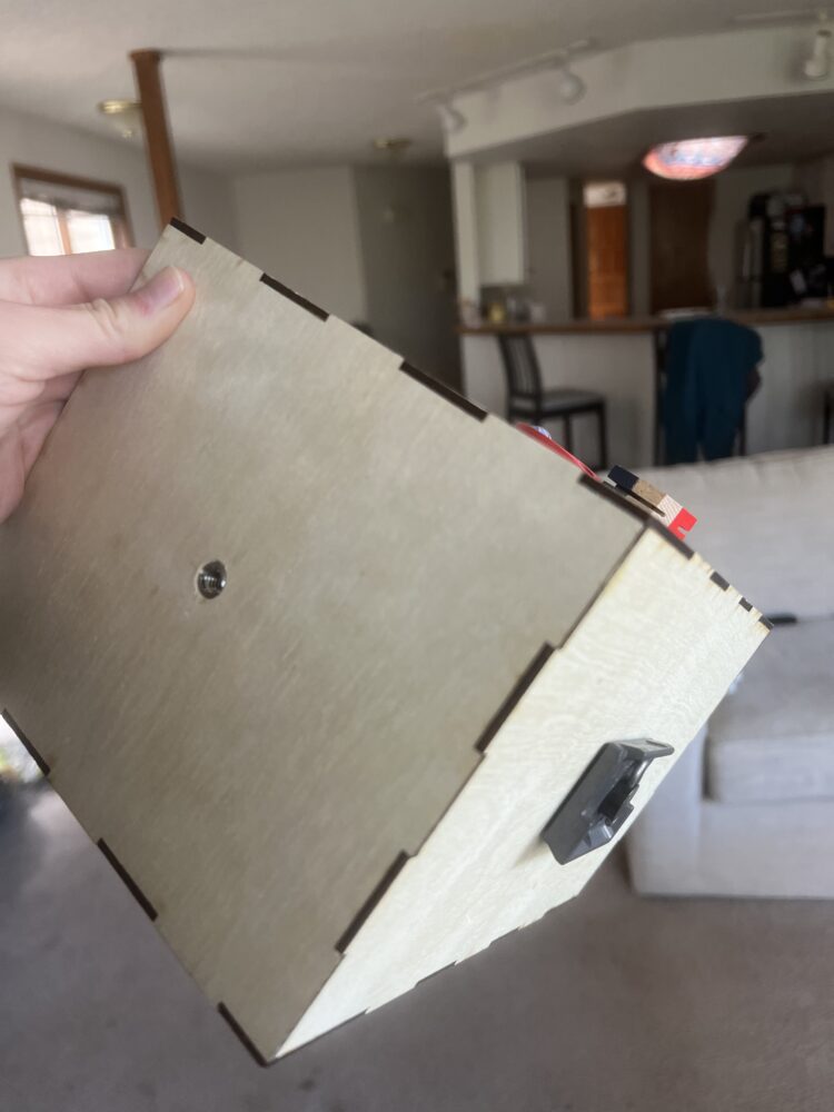
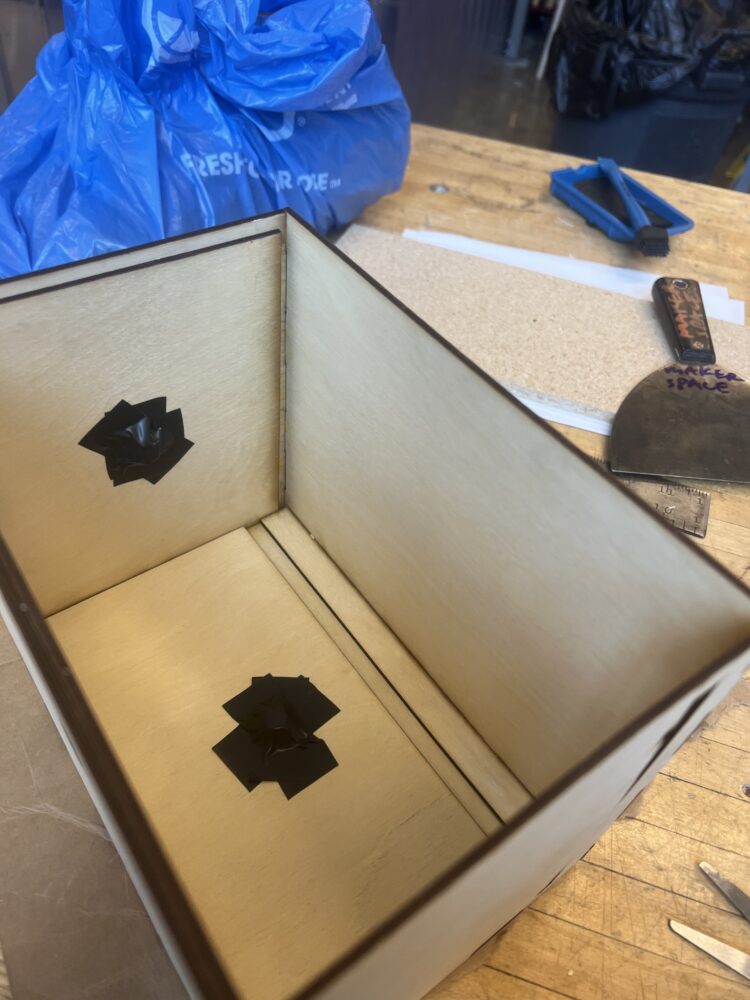
I installed 1/4-20 threaded inserts on two sides of the box so I could mount the camera on a tripod in landscape and portrait orientation.

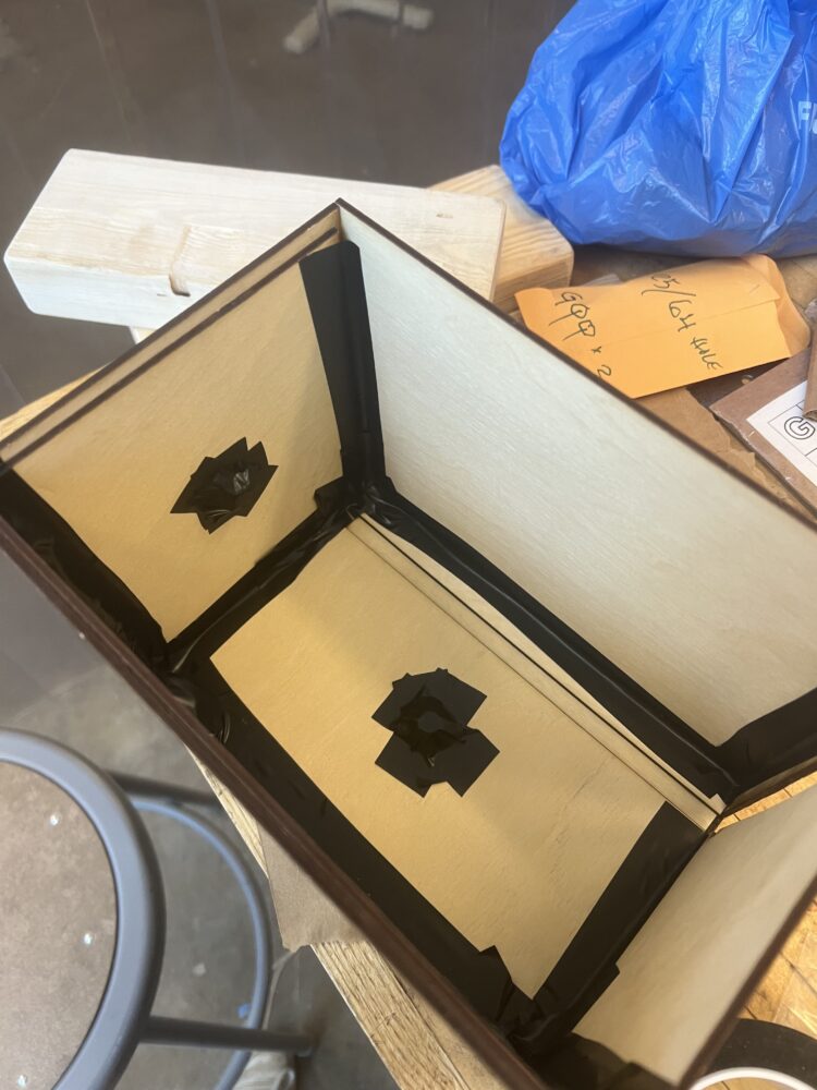
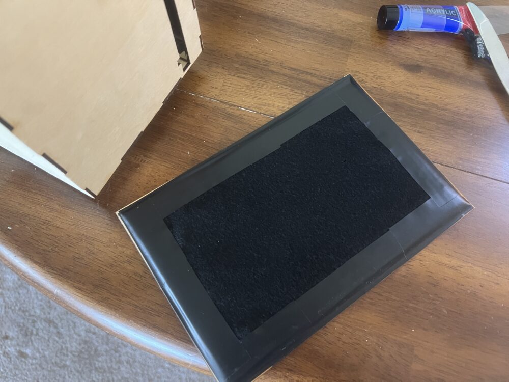
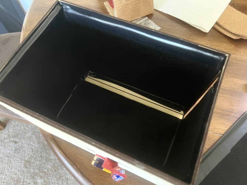
To start light-proofing the box and lid, I covered the internal corners, edges, and threaded inserts with black vinyl tape. I then glued black felt on the walls and further taped the edges. This is so that light doesn’t leak in where the corners or edges are, and so light doesn’t bounce off the walls. You only want light from the pinhole to enter and land directly on the photo paper.
Shutter & Accessories:
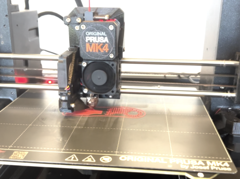
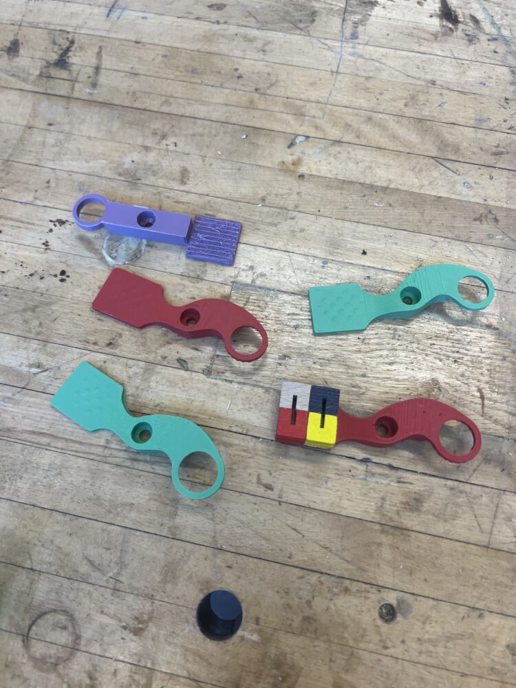
Many iterations of the shutter were 3D printed to get the correct dimensions to allow the marble to roll without falling out. I also 3D printed the blue handle on the paper slide. I ventured to the Into The Wind toy store on Pearl Street to get fun accessories that reminded me of the iSpy aesthetic and found ways to incorporate these on the shutter and paper slide. I sanded and painted the photo slide handle a darker blue to better match the aesthetic.

Taking Pictures:
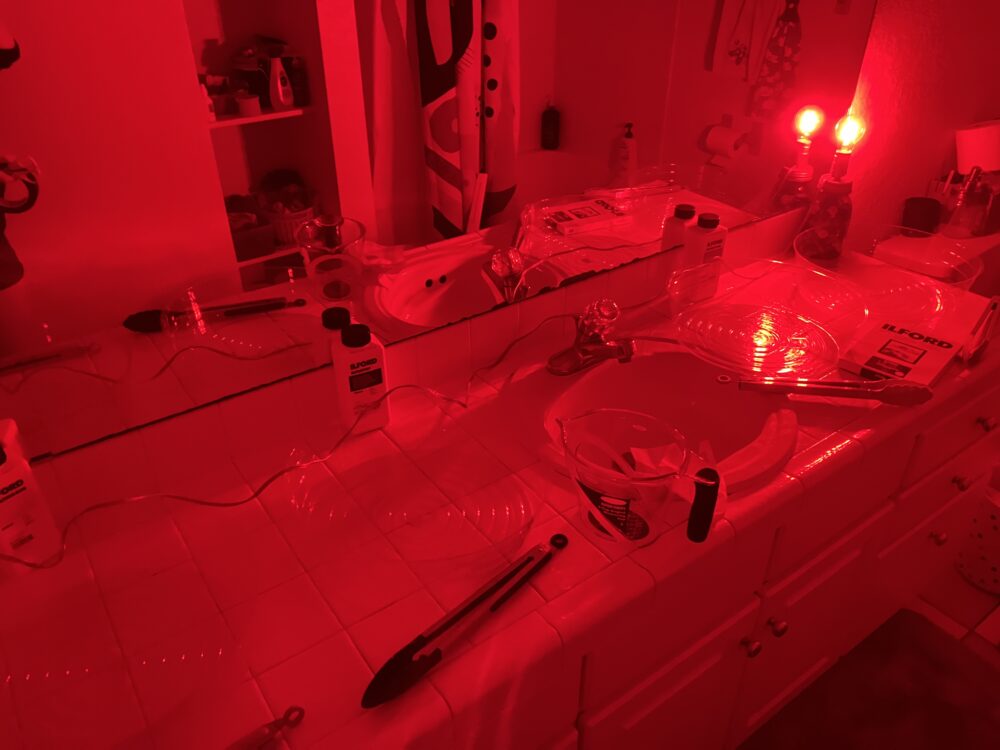
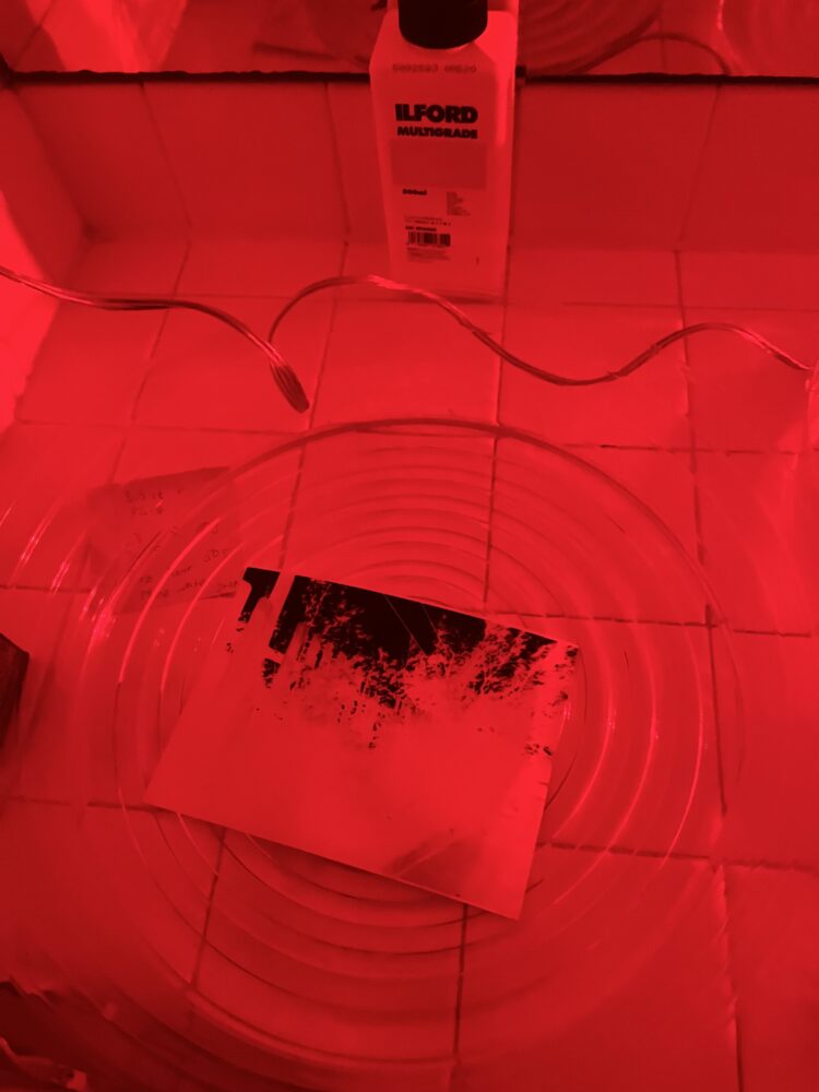
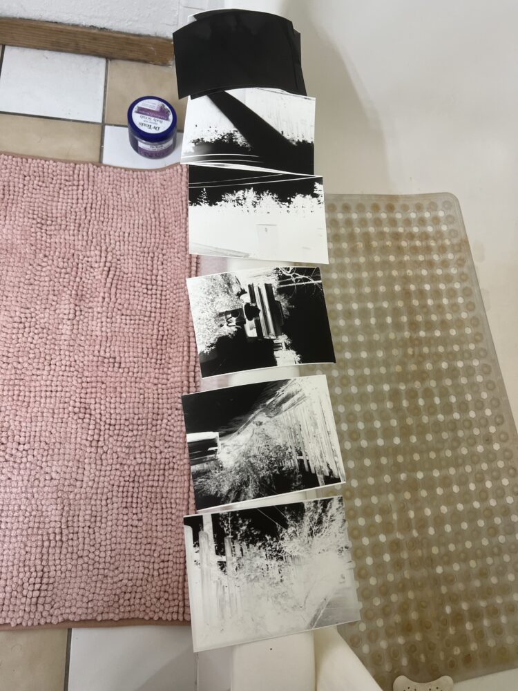
After the camera was assembled, I was able to try it out! To do so, I needed to set up a dark room where I could load the light-sensitive paper in and out of the camera, as well as develop the exposed images. With a red bulb (the paper is less sensitive to red light), I set up the required chemical baths for developing the images.
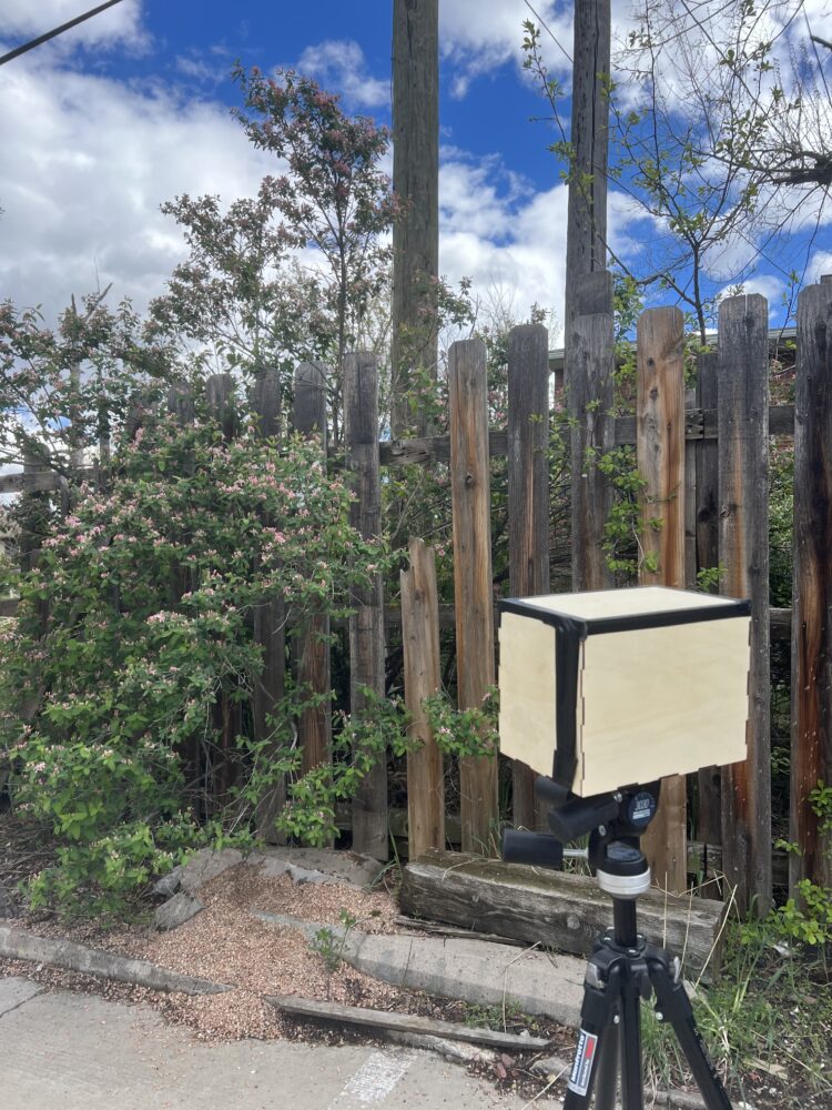
I loaded the photo paper onto the paper slide and then loaded this slide into the camera. I brought the camera outside to take a picture and experimented with different exposure times recommended from The Pinhole Camera book and a calculator [9] based on the f-stop of the camera and the ISO of the photo paper.
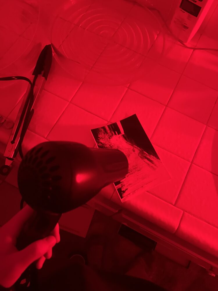
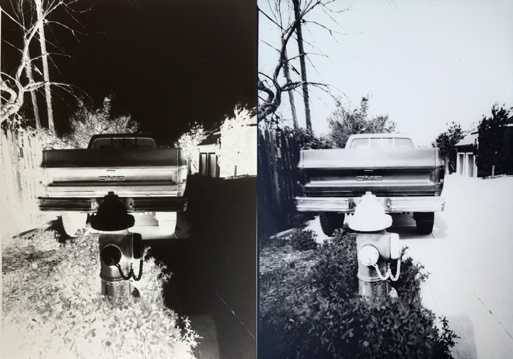
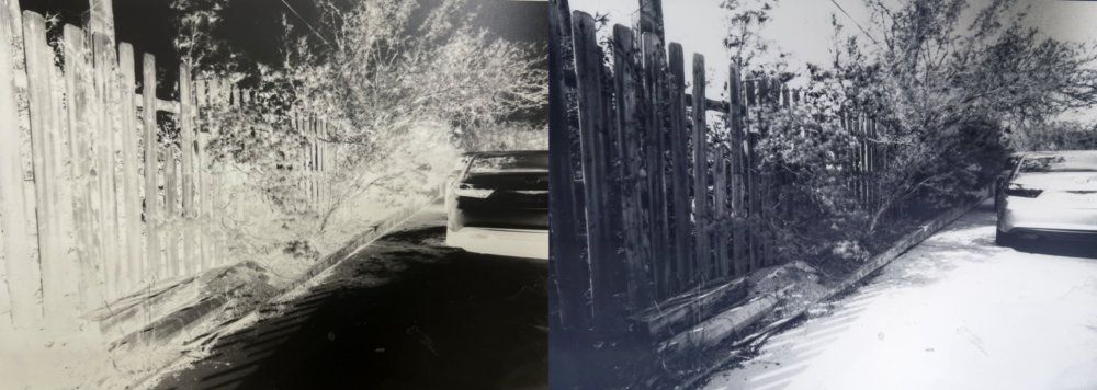
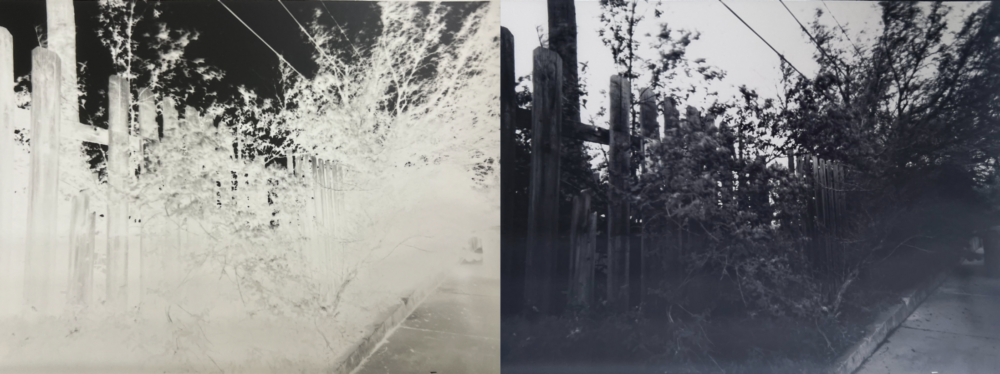
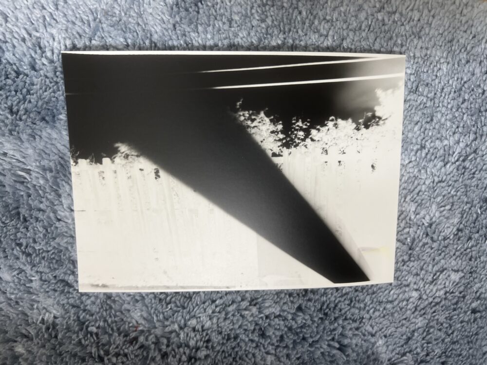
After the exposure time, the shutter returns to the covering position and the camera is brought back to the darkroom. The paper is removed from the camera washed in developer, stopper, fixer, and water baths then dried. This process reveals a negative image (where the parts exposed to the most light appear black). I did not have the right tools to create a contact print, so I scanned the negative prints and then inverted them in Lightroom to create a positive image.

Challenges:
1. I did not pay close attention to the Amazon description of the wood sheets I ordered, and the thickness measured less than 1/8″. I had to redo my CAD after my material arrived and was measured.
2. My first few exposures revealed light leaks on lid edges. I had to tape down all edges of the lid and use the paper slide without the decorative handle to get a correctly exposed image. This means my camera looks a little aesthetically different while in use.
3. I was in resource competition for the ITLL 3D printers with freshman approaching expo. My handle print ran out of filament despite the slicer software saying there was enough (never trust the slicer). Rather than reprint I decided to use this as a creative opportunity to add the extra wood panel with tiny dice glued on.
4. I initially wanted to sand my PLA components to get rid of the layer lines. However, I was worried about sanding the tin parts of the shutter and didn’t want to go through the process of fully sanding a photo slide handle I wouldn’t be using it much, so I ended up painting it.
What is next?
I am really proud of the camera I created! This has provided a creative opportunity to take pictures that are a different aesthetic my usual, and a slower and more informative analog image-creating process compared to the digital photography that I am used to.
I am excited to continue to take pictures. I think it would also be fun to add a shutter mechanism that is automatic, as detailed in some previous posts.
References:
[1] https://news.smugmug.com/a-beginners-guide-to-pinhole-photography-ce7cf6b06fcb [2] https://m.media-amazon.com/images/I/71sWQ2lqKPL._AC_UF1000,1000_QL80_DpWeblab_.jpg [3] https://www.reddit.com/r/nostalgia/comments/70l1ch/can_we_talk_about_how_incredible_the_photography/ [4] https://www.instructables.com/Design-and-Build-your-own-Pinhole-Camera/ [5] https://www.kickstarter.com/projects/davidmhancock/large-format-pinhole-cameras-to-build-at-home [6] https://en.wikipedia.org/wiki/Pinhole_camera
1 Comment. Leave new
Hi Katie! Your project is awesome and I loved seeing the photos you made with the end product. I also love the aesthetic you made it in – it’s really creative. Do you think you would try making other pinhole cameras with different pinhole sizes?