
Throughout this semester I have had a great experience when it came to the process of coming up with and creating my final project. For those of you who may have not seen my project before, my goal was to take inspiration from the flat iron mountain range to create a dynamic piece of wall art that would tie together with my upcycle project that I had created at the beginning of this semester which incorporates wire-twisted wall-mounted rock climbers. To accomplish this, I decided to use an image of the silhouette of the flat iron mountain range which I could then scale to the desired size and laser cut using the ITLL laser cutters at CU Boulder. Once my template was created I then decided to buy individually addressable LEDs that I was able to program and control through the use of a RedBoard and photoresistor. For my dynamic objective, I decided that I would like the back lighting of my flat iron silhouette to mirror the color temperature and brightness to that of the natural outdoor light. With some time and adjustments to the code for my lighting, I am very pleased with the end result for this project.

As with any project, I needed to create a timeline that would make completion feasible within the short time-frame that we had. Accordingly, I wanted to tie my timeline to my fabrication process so that I made sure to hit my major milestones within the range that was acceptable to reach my end goal. My first step was to precure all the materials that I would need for final assembly. For this stage I allocated 2 weeks to account for lead time for any products that need to be ordered, luckily everything came in under this allocated time frame which enabled me to proceed to the setup fabrication process of my project. For this stage, I decided on 3 weeks of time in order to make sure all of my sub-elements were made with precision. This included laser cutting the flat irons out of MDF wood, wiring and soldering my individually addressable LEDs to my RedBoard, 3D-Printing out a PCB box to house all of my electrical components, and wiring a photo resistor that I inevitably set in my windowsill to actively detect daylight.
Fortunately, I was able to accomplish all of this with barely enough time to spare which enabled me to move onto the most challenging phase of my project. As much time as I have had with coding, I am still not an expert with Arduino code so I enlisted the help of Ethan Sachez to provide technical assistance to make sure that my LEDs color and brightness accurately resembled the time of day that the photoresistor was detecting. 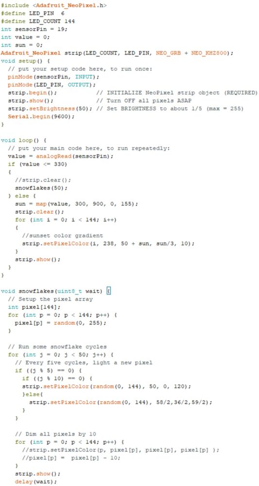
For this stage I made sure to allocate 2 full weeks just incase excessive debugging was necessary. As you can see, the end code is a bit complex and it incorporates a base library of LED lighting control that was provided by https://lastminuteengineers.com/ws2812b-arduino-tutorial/. Regardless, after a week of trial and error, we were able to successfully have a working combination of LED -> RedBoard -> Photoresistor system that I am very happy with.
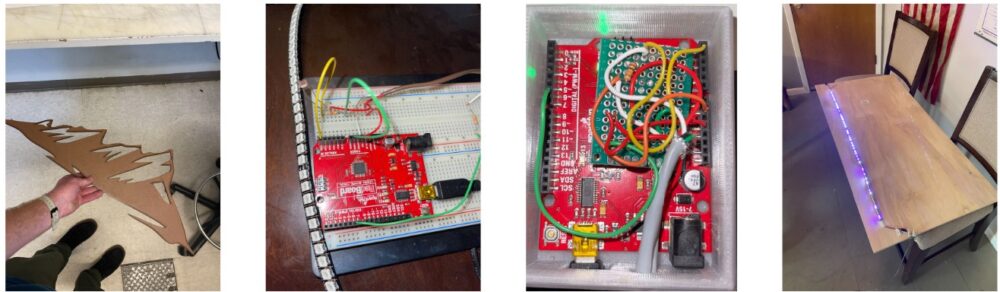 Finally It was time for me to put all the pieces together and hang my project on my wall. With the semester coming to an end, I needed to do this fast and only allocated 2 days to do so. The process for this consisted of painting the flat irons, 3D-printing the spacer for wall mounting, laser cutting out the tray for the LED lights, gluing the mounting pieces onto the back of the flat irons, wiring up to my electronics control box, and then positioning the mountains on my wall and photo resistor in my window sill. Fortunately, I was able to make this happen in one day.
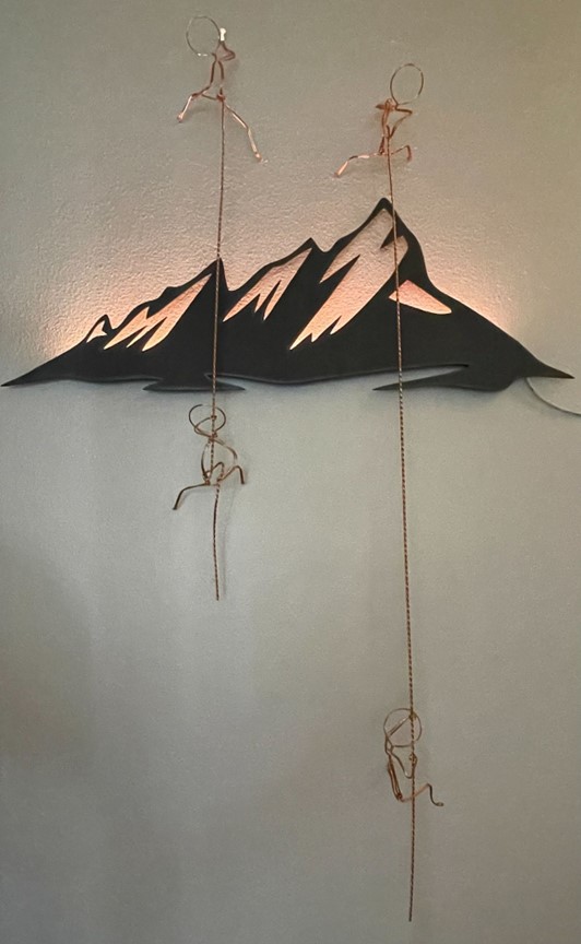
Looking back to my original plans for this project compared to where I ended, I am very pleased to see that I was able to meet all of my original requirements. From the Laser cut flat irons to the PCB control system, I have a final project that I am truly proud of. If there were to be one thing that I would change; if given the time and opportunity to do this project again, I think that I would have liked the cut out of the flat irons to be a bit larger. Regardless, I had a great time being able to work on this project, and I hope it inspires you all to do something similar for your own home.
Below is a link to a video where I simulate the color change of my project as the daylight from outside changes.
1 Comment. Leave new
Hi John, I’m glad it seems your project came together nicely! The paint job looks really nice, at first glance I thought you might have made it out of metal, it was only once I read the post that I realized you had made it out of wood and painted it. Would you consider adding any sort of remote control for additional control over the function in the future? Seems like it could be a cool addition. Anyways, awesome project and I can’t wait to see it at expo!