
Background and Purpose
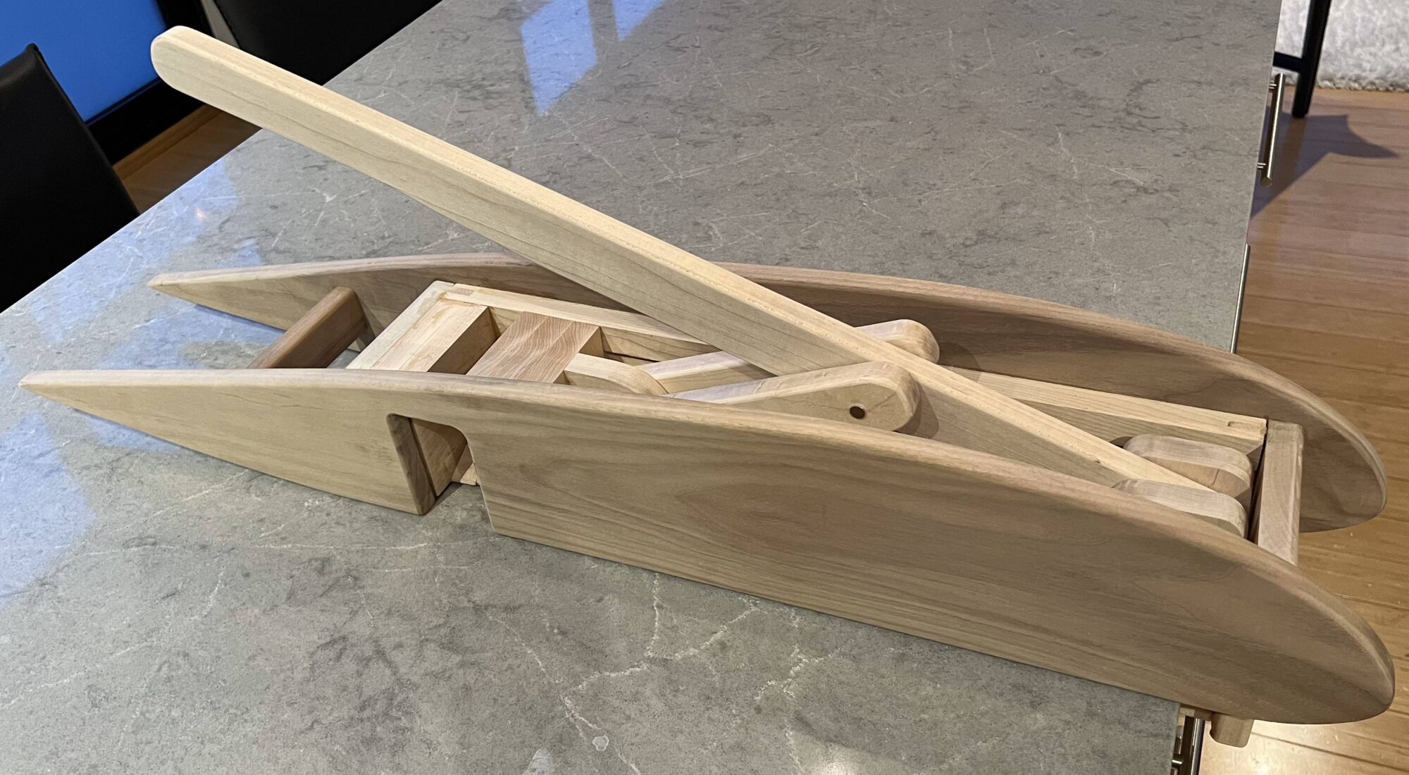
Growing up in a family with German roots, I developed a fondness for sparkling water, finding its refreshing taste irresistible. However, this preference led to accumulating numerous aluminum cans, all destined for the recycling bin. The sheer volume of cans occupied significant space, necessitating frequent emptying of the recycling bin. In contrast to Michigan, where I previously lived and benefited from store credits for bottle returns, such incentives are not available in my current location. To address this issue and streamline recycling efforts, I embarked on creating an aluminum can crusher, showcased in Figure 1. This endeavor not only served a practical purpose but also provided an opportunity to delve into woodworking, exploring diverse tools and techniques essential for achieving intricate design elements in wood.
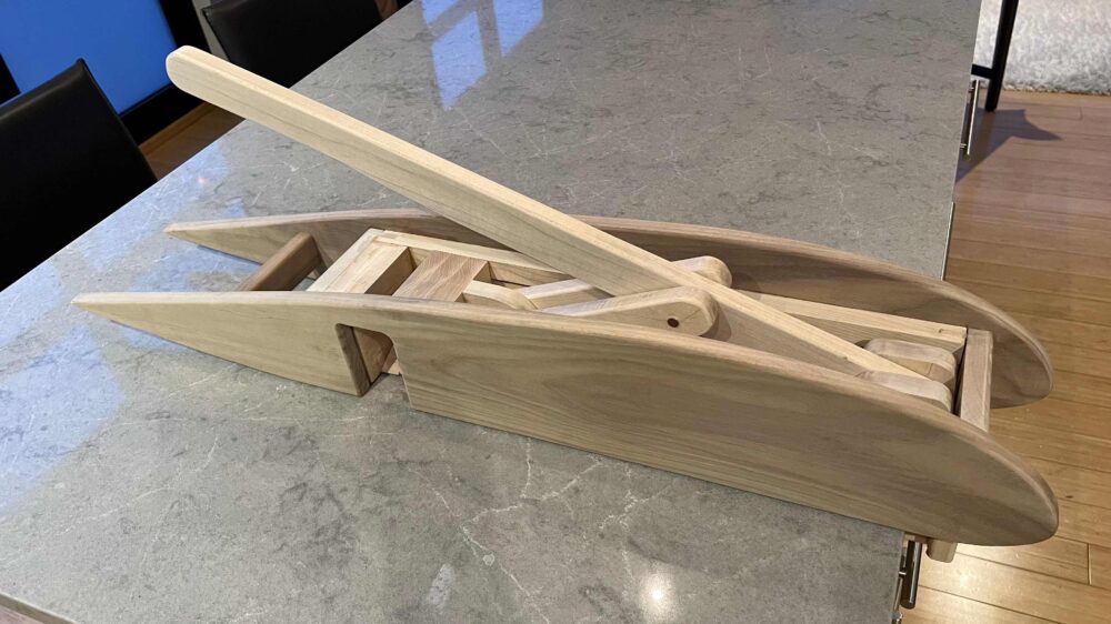
Figure 1
Vision and Aesthetic
The artistic vision I had for the device was that it incorporates clean curves and has an uncluttered look. The profile of the design when viewed from the side takes on the aesthetic of an airfoil. An airfoil, also known as an aerofoil, is a shape designed to produce lift when air flows around it. It is a key component of wings on airplanes and other aerodynamic surfaces. The shape of an airfoil is asymmetrical, with the upper surface (known as the upper camber) typically curved more than the lower surface (lower camber). This asymmetry contributes to the generation of lift. This profile will cover some of the moving components and linkages that are used for the mechanical design. Because of this, the design will have a hint of minimalism as the profile of the wing and the lever handle are the only components that can be seen when viewed from the side. The material I used for the profile of the airfoil was made out of walnut which I later sanded so it has a very smooth and soft finish. The components that needed to handle larger forces and stresses were made out of high quality maple. Maple is a very strong and dense wood and has material properties which make it an ideal material for these mechanical components.
The main aesthetic that I was after for this crusher was the aerodynamic aesthetic. It also has a hint of minimalism because of its streamlined profile with no exposed fasteners. The wood itself is not the main aesthetic, however, it does contribute to the aesthetic by adding natural warmth, texture, and organic qualities. The beauty of wood lies in its diverse grain patterns, colors, and the way it responds to light. The lighter and darker color of the wood is complemented and contrasted well by the lighter toned countertop. One can argue that there is a hint of an industrial aesthetic that the design will introduce into the space when looked at from above because all of the moving pieces, linkages, fasteners, and other components of the mechanical device can be seen. The main component of the design will be the aerodynamic profile of the airfoil.
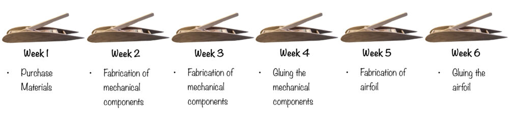
Timeline:
Once the design of the airfoil crusher was finalized, I begun the fabrication portion of the project which was divided into 6 weeks as seen in the timeline below.
Fabrication:
The materials used in the airfoil crusher were purchased from hardware stores and online vendors. The complete list of materials and components that were used in the final product are listed below.
- 12 feet of maple
- 12 feet of walnut
- Titebond III
- Chicago screws for linkages to reduce erosion
- Furniture sliders
The main tools that were used to fabricate the various components were the miter saw, table saw, band saw, orbital sander, and router table. In general, the miter saw was used for short cuts to cut down longer planks of wood while the table saw was used to make longer cuts and joints. The router table was used to add round overs to the edges of components and cut a variety of profiles and grooves. A router table is a stationary woodworking machine in which a vertically oriented spindle of a woodworking router protrudes from the machine table and can be spun at speeds typically between 3000 and 24,000 rpm.
The first component that I completed were the maple side walls of the mechanical crusher as seen in Figure 2.
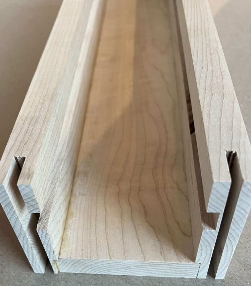
Figure 2
The groove running along the length of the front edge was achieved by using a dado blade on the table saw. The dado blade gives a very nice finish and is designed to cut notches and grooves with clean and sharp corners. These grooves hold a wooden beam with a different fiber orientation that will bump up against the countertop and prevent the crusher from sliding across the table. The bottom of these walls also have a 1/8 inch groove which allows for a stronger joint when glued. This also makes the gluing process much easier because this adds an extra plane in which the joint will properly line up with. The groves on the interior walls run the entire way up and down the crusher because these are the slots in which the crushing plate seen in Figure x will slide along during use. This feature was accomplished by using the router table with a rabbet router bit as seen in Figure 3.
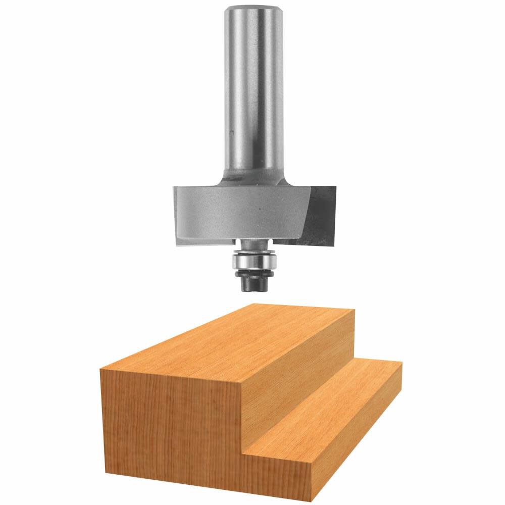
Figure 3
The next component that was fabricated was the crushing plate which can be seen in Figure 4. This is the block that crushes the can as a result of the forces that get transferred to it from the linkage system seen in Figure 8. While assembling the block, my goal was to have the grain lines line up with one another as much as possible because this would make it look like one block of maple instead of 3 separate blocks glued together and I am very happy with how it turned out. The interfaces between them were much less noticeable after thoroughly sanding the surfaces.
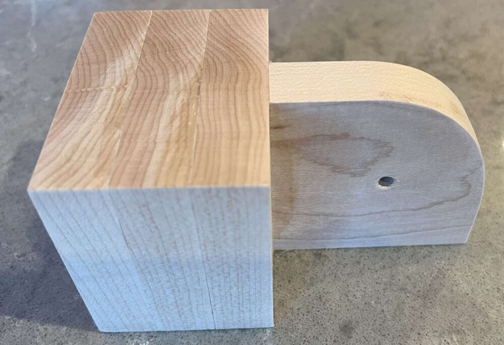
Figure 4
The round corners of the crushing block and linkage system were achieved by using the band saw to cut a radius into the wood. The round corners were then sanded which gave each corner a uniform radius. The next components that were completed were the base plate on the bottom and the crushing wall on the left seen in Figure 5. The base needed one notch cut into it which serves as the chute and ramp that the can will roll down and ultimately land in the recycling bin.
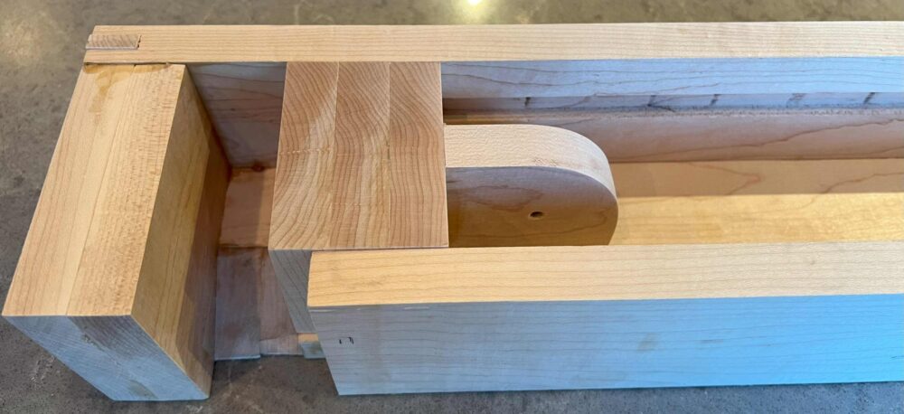
Figure 5
The linkage system components seen in Figure 6 were the last of the mechanical components that needed to be fabricated. The holes in each of the components are where the Chicago binding fasteners are used to connect the linkage system. The main lever as well as linkages have a round profile edge that was achieved using a round-over bit on the router table. All of the edges and surfaces were sanded to achieve a very soft and smooth finish which makes it more ergonomic for the user. The Chicago binding screws seen in Figure 7 have a smooth and polished finish which minimizes the erosion of the wooden surfaces that contact the screw. It also gives a very clean and polished finished to the joints as they are very low profile fasteners when viewed from the side.
Figure 6
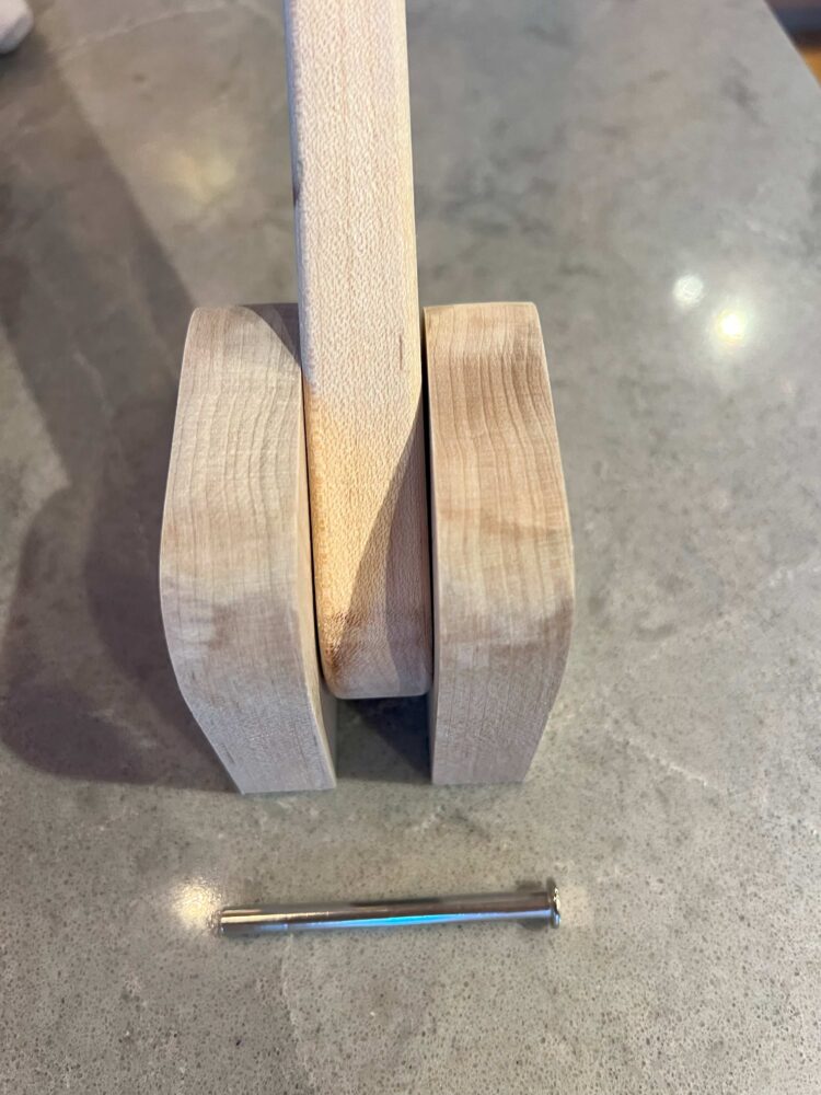
Figure 7
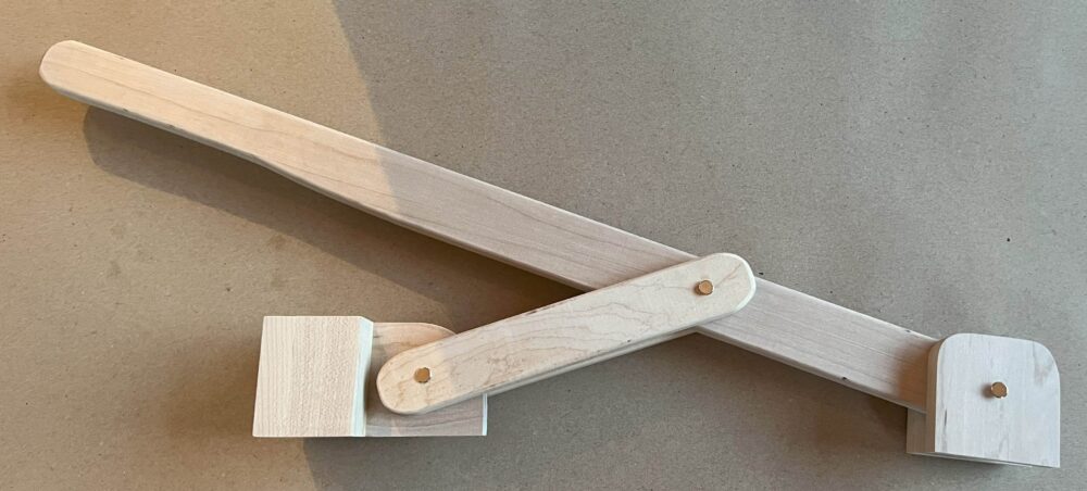
Figure 8
After completing the fabrication process of all the components for the mechanical portion of the can crusher, I assembled everything to ensure proper alignment of all the components and interfaces seen in Figure 9. I performed this step without glue in case there were any adjustments that were needed such as sanding certain faces or edges.
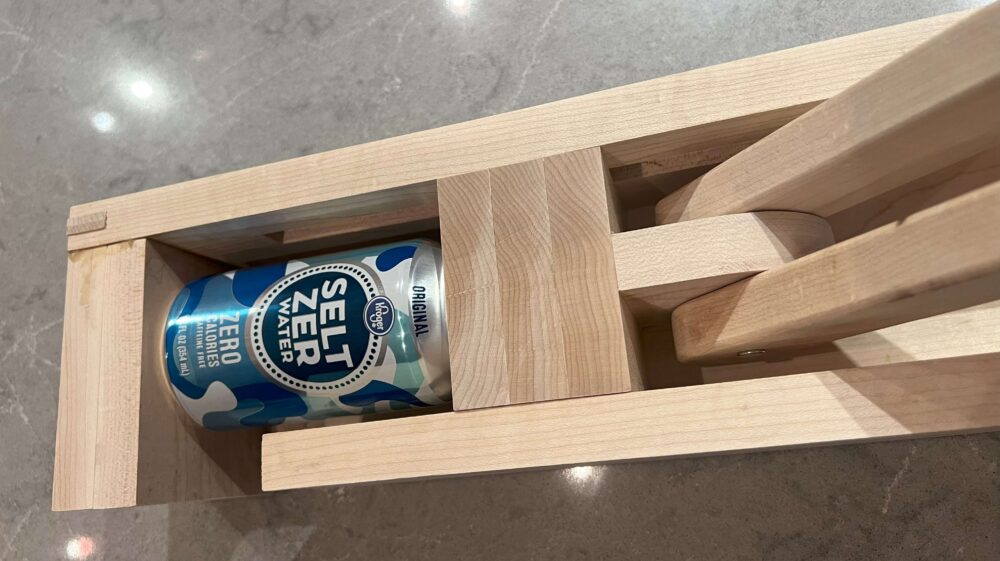
Figure 9
After sanding various faces of the crushing block, I moved on to assembling and gluing the components which was done using Titebond III wood glue. This was a difficult process because the glue acts as a lubricant which means that the parts had the tendency to move from their ideal position and locations when getting clamped. To ensure proper alignment I used different pieces of wood as planes and put plastic from plastic bags and placed this between the wooden support plane and gluing interface which can easily be pealed off after the gluing process is complete. This can be seen in Figure 10.
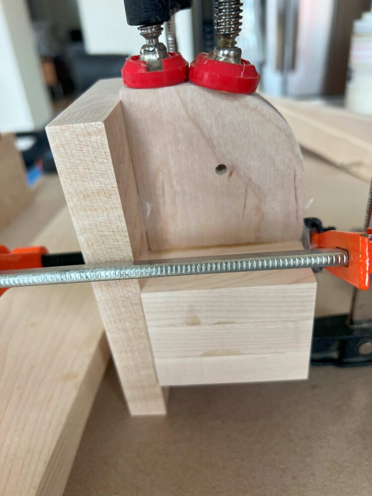
Figure 10
The can crusher had to be assembled and glued in phases because there were to many components to glue at once. The crushing block was glued first. This is because it was one of the easiest parts to glue together and there was not a lot of risk because it is a relatively simple component that could be easily sanded to remove any defects or edges left behind. I also wanted to get some experience and practice with this process before gluing the critical components. The main lesson learned from the gluing process is to add as many reference and alignment plains as possible as this will minimize the chance of the parts sliding when being pressed together with clamps. After getting comfortable with the gluing process i moved on to gluing the main walls to the base of the crusher as seen in Figure 11.
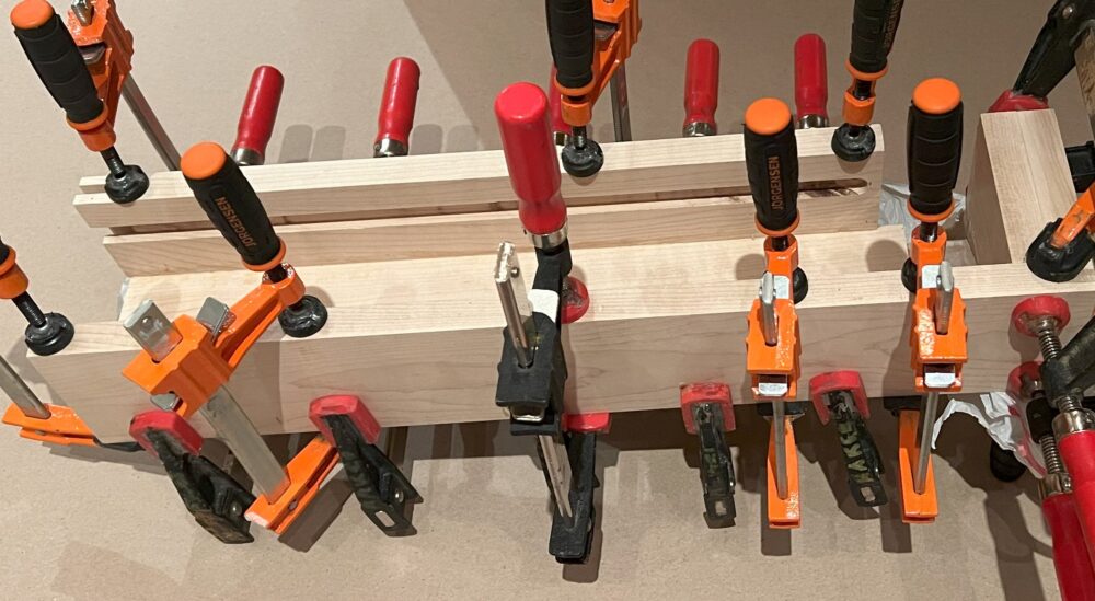
Figure 11
After applying the glue to all of the interfacing surfaces, the clamps were strategically placed at various points along the joint with a higher density of clamps used at high stress joints. The clamping time I used for all of the joints was 24 hours. I would then remove the clamps and let the glue cure another 24 hours before applying any stress to the joints. This was almost double than the curing time recommended by the manufacturer. This is also why the assembly process took about a week.
Once the main walls of the crusher were glued and cured as seen in Figure 2, the next step was to install the rails on the crushing block which slide in grooves of the wall to keep the crushing block in proper orientation and position during the crushing process. The low friction furniture sliders seen in Figure 12 were used as the rails for the crushing block.
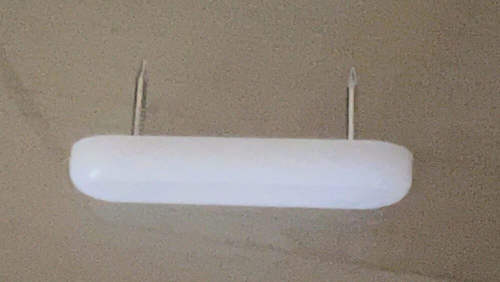
Figure 12
The furniture sliders are ideal for this application because the ends are round which allows for them to slide over imperfections in the groove and prevents from jamming. The plastic material is also very durable and low friction which allows the crushing block to slide efficiently along the groove as seen in Figure 13.
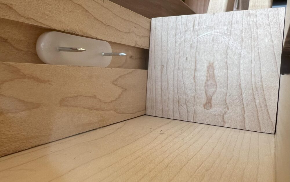
Figure 13
The furniture sliders were installed by drilling pilot holes in the precise locations on the sides of the crushing plate. They were then gently hammered into the crushing block. The pilot holes minimized the possibility of the nails getting bent during the hammering process and it allowed for proper alignment of the furniture slider. After completing the installation of the crushing block, the linkage system was installed. This was also done using the Titebond III glue. This process can be seen in Figure 14.
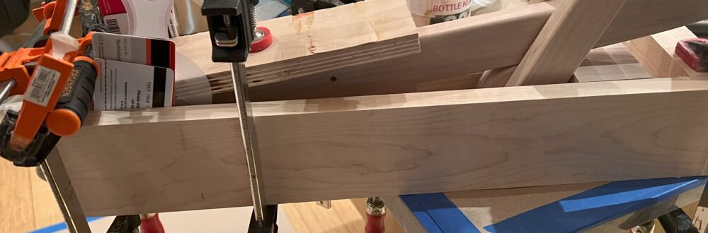
Figure 14
The various cards and materials were used to apply pressure and keep the components properly aligned during the gluing and curing process. The linkage system had to be centered and this was accomplished by using spacers I made out of felt furniture sliders covered in plastic to prevent them from being glued as well as seen in Figure 15.
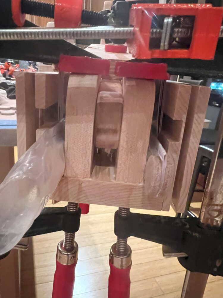
Figure 15
After the glue between the linkage system and base plate was cured, I begun some testing to see how well the crusher does its job. It works very well as seen in Figure 16. The linkage system and crushing plate move very smoothly and effortlessly. There are lubricants available for wooden interfaces which is something that was recommended by the woodshop staff before starting the project. After testing, there was no need for a lubricant because the crushing plate slides very easily to where it just slides from the weight of the lever.
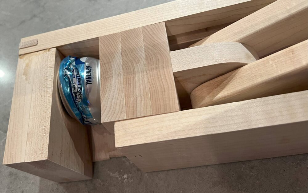
Figure 16
The next step was to design the airfoil. This process can be seen in Figure 17 the white sheet of paper that is covering part of the airfoil is the profile of the crusher from the side. I wanted to ensure that the can crusher does not have any sharp edges or parts that exceed from the airfoil other than the lever arm. By printing out the scale size of the component, it helped me visualize and finalize the dimensions of the ideal airfoil.
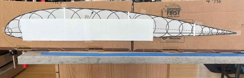
Figure 17
Once I knew where I wanted the crusher to sit with respect to the location of the airfoil, I traced the airfoil on a heavy duty paper seen in Figure 18. I then used the heavy duty paper to trace the design of the airfoil onto the walnut plank.
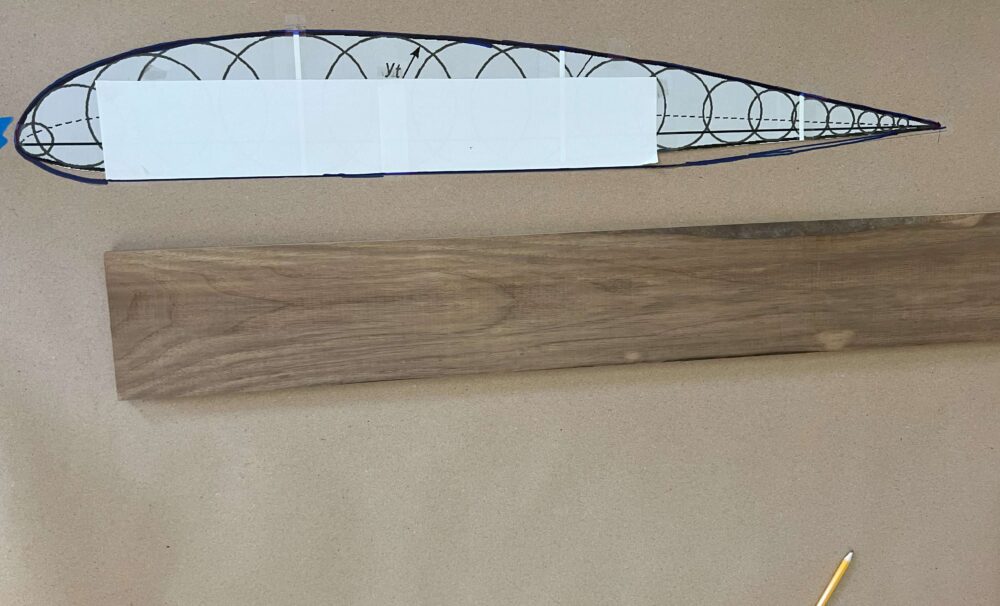
Figure 18
I used a bandsaw to achieve the airfoil shape desired in the wooden plank. I then used double sided tape and used the router table to make a second airfoil that is identical to the first by using a pattern router bit seen in Figure 19. This process works by using the first airfoil as a template which runs along the bottom part of the pattern router and the top starts taking the shape of the airfoil as it runs along the edge of the router.
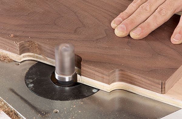
Figure 19
After fabricating the two airfoils, it was time to glue them to the mechanical component. This process can be seen in Figure 20. This was the most difficult component to glue because the glue allows the airfoils to easily adjust and move around as it acts like a lubricant.
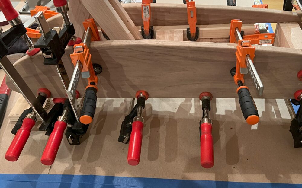
Figure 20
After letting the airfoils cure to the crusher, I added some features to the design allowing for a more finished look. The first feature I added was an ergonomic handle made of walnut seen in Figure 21. The handle has rounded edges and gives the user a safe and easy point at which to grab when moving it. It is placed in a way that allows the user to efficiently slide fingers underneath it and grab on to it.
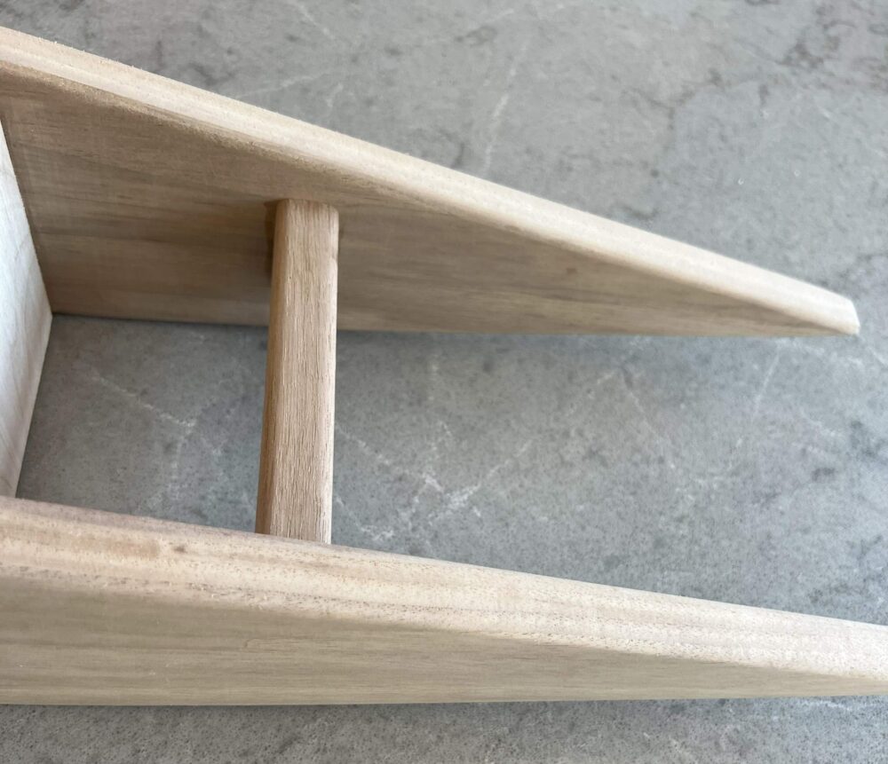 Figure 21
The next component I added was the notch that slides underneath the countertop seen in Figure 22. This notch is important because it prevents the front end of the airfoil from lifting up above the countertop. If this were to happen the crusher has a tendency to slide across the countertop. It was also designed to serve as the second handle. All of the corners and edges are rounded to allow for a more comfortable and ergonomic feel when holding the device. This feature also serves as the hanging mechanism that securely latches onto the top of a shelving unit during storage as seen in Figure 23.
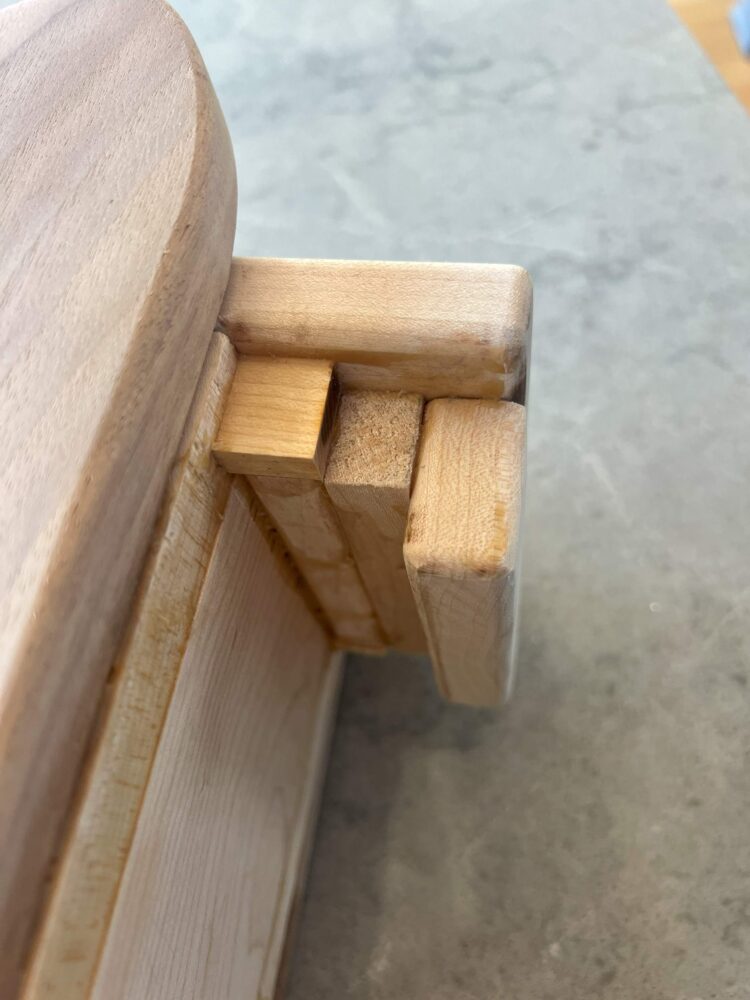
Figure 22
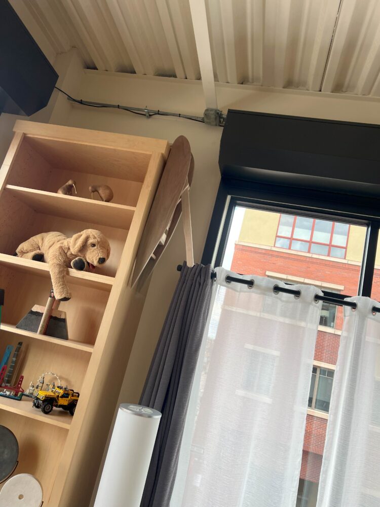
Figure 23
The last feature I added was a flat piece of maple with rounded edges to the front of the crusher. This gave the piece a very finished and minimalistic look when viewed from the front as seen in Figure 24.
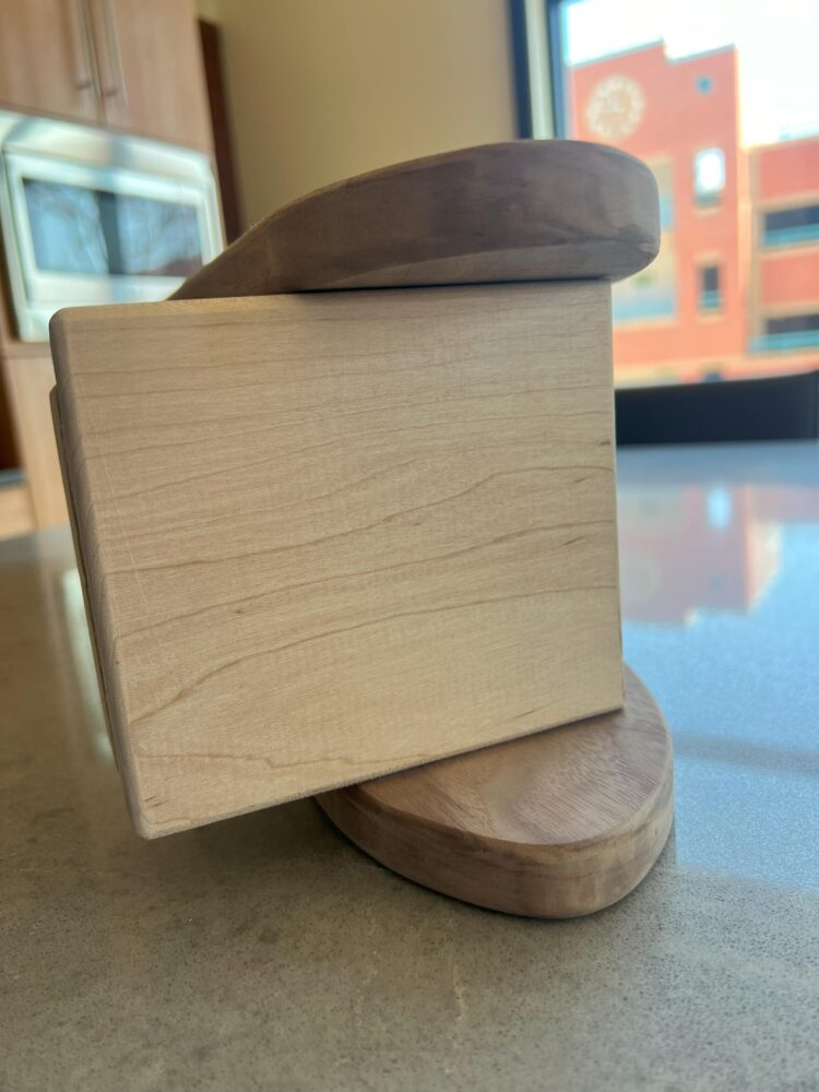
Figure 24
The completed can crusher can be seen in Figures 25-29 below.
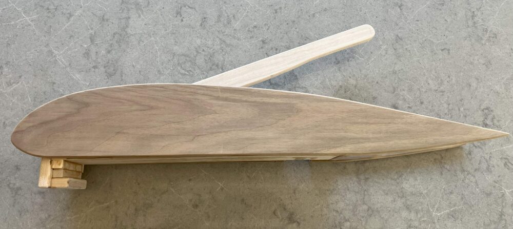
Figure 25
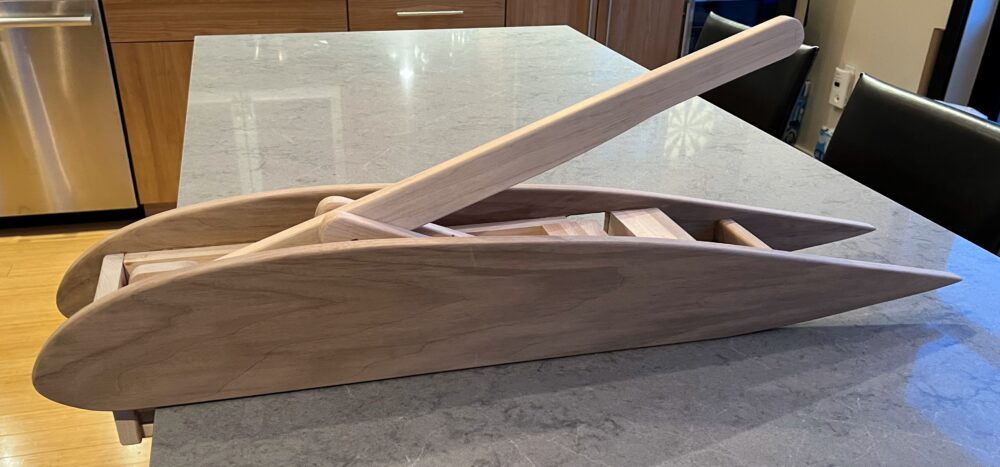
Figure 26

Figure 27
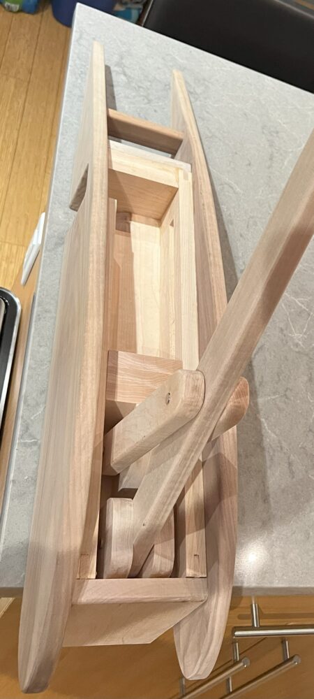
Figure 28
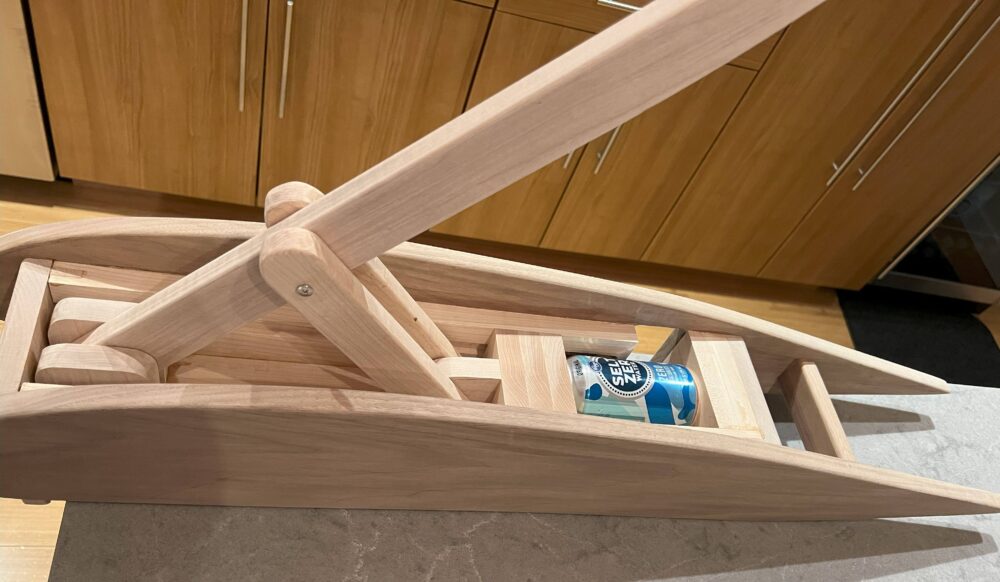
Figure 29
Specifications
- The aesthetic of the device was the most important spec as it was an aesthetics in design class. The aesthetic goals for this design were that it would look aerodynamic, with a hint of minimalism. The main aesthetic component of the design was the profile of the aerodynamic airfoil. The wood itself was not an aesthetic; however, it did contribute to the aesthetic by adding natural warmth, texture, and organic qualities. The beauty of wood lay in its diverse grain patterns, colors, and the way it responded to light. The lighter and darker color of the wood was complemented and contrasted well by the lighter-toned countertop. There was also an industrial aesthetic that the design introduced into the space when looked at from above because all of the moving pieces, linkages, fasteners, and other components of the mechanical device could be seen.
- Safety was also a very important specification as I did not want to injure any fingers when using the device. This meant that there were no pinch points or sharp edges at which the user could pinch or cut themselves. The device also had channels where the countertop could slide into. This ultimately kept the module from sliding across the countertop or from being flipped over if the user inputted a force at different angles.
- The functionality of the device was important as its main job was to crush aluminum cans with ease. A standard 12 oz aluminum can was 4.83 inches tall, and the device had to crush the can to a new length of 1.75 inches or less. The device also had to accommodate a standard plastic water bottle, so the feeder had to be greater than 8.5 inches.
- Human Factors were also accounted for in the design. I designed the device for myself, and therefore my build allowed me to comfortably use a 2-foot lever without putting myself in any uncomfortable positions. The handle also had an ergonomic grip for fingers, which prevented slipping and sliding. After the can or plastic bottle got crushed, it automatically dispensed from the device out of an opening in the side. The force of gravity was used to remove the crushed object out of the feeder, and it then automatically fell into the recycling bin. This made the process more efficient. Any components that interfaced with the user were not too long or short because this could sacrifice and negatively affect the ergonomics as well as the power and force needed to be inputted by the user. The user crushed the can using their strength by taking advantage of leverage and physics, and the user was considered to be the average adult. The user did not have to apply more than 20 pounds of force to the lever to crush the can.
- Size and Weight were also important specs. A slim profile was needed because when the device was not in use, I hung it from a cabinet wall in the kitchen area. Therefore, the device was also under 30 pounds, which made it easier to transport and move around.
Conclusion
In conclusion, the journey of designing and fabricating the airfoil-inspired aluminum can crusher has been a fulfilling and educational experience. Originating from a personal passion for sparkling water and a desire to reduce waste volume, this project not only addressed a practical need but also provided an avenue to explore woodworking techniques and design aesthetics.
The vision for the can crusher was driven by a desire for functionality, aesthetics, and safety. The aerodynamic profile of the airfoil, mimicking the principles of lift generation, contributed to the device’s streamlined appearance and minimalist appeal. Utilizing walnut for the airfoil profile added warmth and natural texture, complemented by the structural strength of high-quality maple for critical components.
Throughout the fabrication process, attention to detail was paramount. Precise cuts using tools like the miter saw and router table ensured the components fit seamlessly, while ergonomic considerations led to features like rounded edges and an easy-to-grip handle. Safety was prioritized with the absence of sharp edges or pinch points, enhancing user experience and usability.
The functionality of the can crusher met its specifications effectively, accommodating standard aluminum cans and plastic water bottles with ease. Human factors were carefully considered to ensure comfort and efficiency during use, with the lever system designed for optimal force application without undue strain.
The final product embodies a blend of aesthetics, functionality, and craftsmanship. Its slim profile and lightweight nature make it suitable for everyday use, while the industrial-inspired view from above adds a unique visual element to the space. If I were to recreate this project in the future, I would modify the chute design to ensure that the ramp extends further into the crusher. This adjustment would prevent the can from resting on the corner of the chute, ensuring a longer ramp for effective discharge of the can.
Overall, this project not only achieved its intended purpose of crushing aluminum cans efficiently but also served as a platform for learning and honing woodworking skills, exploring design aesthetics, and integrating human-centered considerations into product development.
Now that the airfoil-inspired aluminum can crusher is completed, it will find its place in my daily routine, reducing the volume of aluminum cans in my recycling bin while adding a touch of craftsmanship and functionality to my kitchen space. Its aerodynamic aesthetic and minimalist design contribute to the overall ambiance, blending seamlessly with the existing decor. The sturdy construction and ergonomic features ensure ease of use and durability, making it a reliable tool for crushing cans efficiently. Additionally, the project serves as a testament to the skills and knowledge gained in woodworking and design, paving the way for future projects and creative endeavors.
Credits and References
[1] RPG Woodworking: https://www.youtube.com/watch?v=6JiS1TmXhyI [2] Danimal’s House: https://www.youtube.com/watch?v=S1rUooUhZAo [3] Router Bits: https://blog.acmetools.com/beginners-guide-to-router-bits/
1 Comment. Leave new
Hi Tim,
Wow, this is a very well-thought-out and unique project! I think its function is very unique and practical. You did an excellent job utilizing the woodworking tools available to you, including the router, and the final product looks fantastic! How many hours of manufacturing time were involved?