
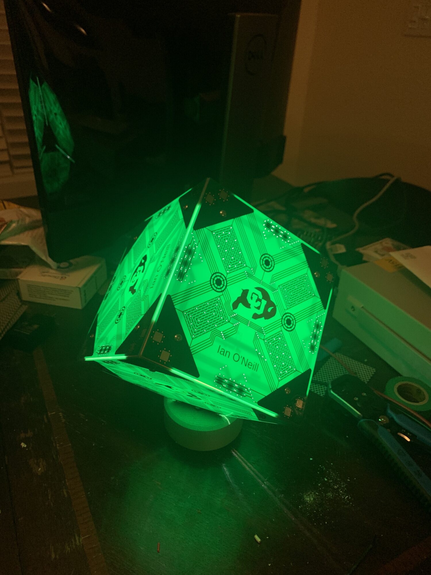
Recap: PCB Lamp
Over the course of this semester and some of my previous post, I have been documenting the work done in order to design, manufacture, and assemble a lamp which utilizes PCBs as the main building material. More details can be seen in my previous post: https://www.aesdes.org/2024/04/26/pcb-lamp-the-what-and-why/
Overall, the PCB lamp turned out to be a great success, however, there are still areas to improve upon.
Process Outline and Timeline:
This project was heavy on the design and light on the manufacturing and assembly. This is largely due to the fact that I outsourced the manufacturing of the panels of the lamps
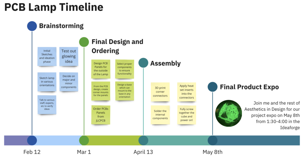
Throughout the semester, I continued to work on various aspects of the project. During the first month, I nearly exclusively worked on the upcycle project, only committing a few hours over the course of the month to the brainstorming process. The design process really kicked off starting in the middle of February. I spent a lot of time deciding what I wanted to build which delayed my schedule. I did eventually complete enough sketching to have a strong idea of where I wanted the design to go.
After the initial brainstorming and sketching phase, I spent time then designing the PCB panels themselves. In order to start on the tracks and artwork, I needed to know the size. In order to do so, I compared various objects around the house to figure out if I thought 6 inches would be acceptable for the lamp. Once the design was complete, I submitted the order right after spring break as I went on another trip for about a week. This allowed time for the PCBs to be manufactured by JLCPCB and arrive with plenty of time to complete the design project.
Finally, I spent approximately one week completing all of the assembly work. Assembly itself was not too challenging of a task as I was able to 3D print the only other additional components I needed.
Assembly Process
The assembly process can be broken down into the following ___ steps:
- Apply heat set inserts
- Assemble the Cube
- Remove one panel to solder on the LED
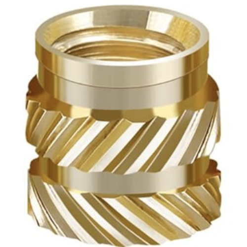
Heat Set Inserts:
Applying heat set inserts is a relatively easy process, it involves using a soldering iron to apply what are essentially nuts melted into a 3D printed component. An example of one is shown below:
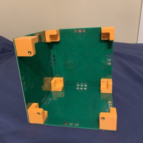
Cube Assembly
The cube can really be assembled in any order desired, but an example of one of the stages I paused at is shown below. It includes half of the panels with all but one of the corner blocks installed.
Solder LED
The LED was soldered using solid core wire in order to suspend the LED in the center of the cube. The soldered LED panel is shown below:
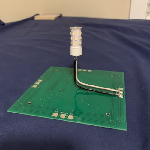
A major benefit of the suspended LED by the solidcore wires is that it minimizes any shadows which might be casted by any sort of larger system.
Future Improvements
As with many of the projects I complete, I always tend to find areas to improve upon beyond any quick fixes. This project is no different and has left me with the following areas I would like to improve. The following list gives a bit of an outline, but I’ll dive into more details following.
- Capacitative touch control
- Integrated Electronics
- Variable brightness
- Battery powered
- Different colors
Capacitative Touch
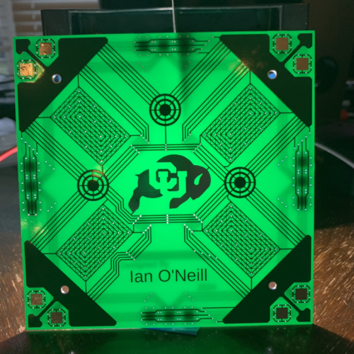
During my design process, one of my stretch goals would be to implement capacitive touch. Unfortunately it proved to not be within the scope of my current work. Part of the design intent behind the PCB layout was to make all of the “artistic” tracks, or the ones which I was simply using to create a more visually appealing aesthetic accessible on one net attributed to capacitive touch.

Careful attention to the layers will show nearly all copper traces on the top layer, or in red in the design shown above are connected to the same net. This would mean that with some software and new hardware, I could implement capacitive touch capabilities into the lamp. I had done some initial exploration into what capacitive touch would take and it seems like on its own it would not be difficult to read whether something is touched or not. The difficulty arises when it needs to control the LED as well due to the relatively high power consumption compared to smaller electronics.
Integrated Electronics
After working with PCBs for a majority of my senior design project, I have grown to enjoy the act of working with PCBs and the challenge they bring. One idea which initially showed itself during the initial phases of this project would be to design a custom microprocessing solution. This would be an overkill method involving me designing my own custom board raspberry pi based board to control all of the electronics. In order to achieve a solution like this, it would require hours of research, reading through datasheets, and design work. Additionally, in a design of this caliber, it would likely not work on the first attempt, likely adding at least 2 weeks of wait time per revision. Due to the significantly larger time required to design and the extended wait times in the case of a failure, I opted to leave a task like this to be for a future project as a fun challenge to work on in my free time.
Variable Brightness
In addition to the variable brightness, I would like to ensure that the lamp can be dimmable. From an electronic standpoint, this would mean I need to include a pulse width modulated (PWM) power output for the LED. Currently, the LED is driven straight off of the battery, however, in order to adjust the brightness, there are two possible methods. One would be to integrate an LED driver with dimming capabilities. These will often take in a PWM signal, however, they will output an analog voltage to the LED to achieve dimming. The second method would be to drive the LED through a mosfet or a transistor using a PWM signal. The rapid on and off of the LED creates effective dimming, undetectable by our eyes when switched over speeds of approximately 100 Hz.
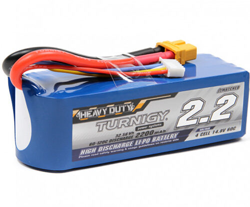
Battery Powered
Currently the lamp is required to remain attached to the base but was designed with intent to eventually make it battery powered. The best way is to utilize a LiPo battery as these are generally the best batteries for their power density. One which I could potentially use is shown below. This battery specifically is a 14.8V, 2.2Ah battery capable of running the LED for at least 5 hours in a row before it needs to move back to the stand.
Color Variations
While I love the color, aesthetic, and look of the green PCB lamps, the aesthetic doesn’t necessarily always fit into the room it is in. One option would be to use black or white PCBs if a more passive effect is desired. As PCB manufacturing capabilities continue to evolve, the color choices increase as well. at JLCPCB, where I manufactured my PCBs, they offer a variety of colors including red, yellow, green, blue, purple, black, or white.
Additionally, they have recently added inkjet printing silkscreen capabilities. While a silkscreen is slightly different than the solder mask color, it could still have a similar effect. This would be something to explore and test out in the future.
Conclusion and What Next
As mentioned in my previous post, this project was a resounding success. While I did not finish with the time to integrate all of the additional features, the lamp still functions perfect as is. I still have quite the work cut out for me, although any future work is just to generate improvements for the project. In its current state, I plan to leave the lamp on my in my room. I am big fan of ambient lighting while writing on paper, doing small chores in my room, or just winding down for the night. This lamp should serve the function perfectly, and in addition, should be very aesthetically pleasing at the same time.
2 Comments. Leave new
Wow Ian! This lamp is so aesthetically pleasing and was clearly a technical task for you as well. You should be proud of what it came out to be. Congrats and I cant wait to see it at expo!
Thanks Riley! I’m excited to be showing it off!