
This week I am going to go through the design and fabrication of my final project I crafted over the last 3 months. As a reminder, my project is an American modern minimalist coffee table that has a hidden bottom table that can swing in and out to extend the surface area of the table. The process for creating this project can be specifically designated into two separate phases, the design and the fabrication phase.
Design Phase
My design goal is to utilize the inspiration of the set of coffee tables that sit inside each other from Lakiq and my understanding of engineering torques and assemblies to create a singular artifact that still gives a second surface that can swing in and out from the rest of the assembly. Now that I have this foundation I was energized to get into designing and so I started to utilize the Computer-Aided Design (CAD) software SOLIDWORKS to start to bring my ideas to life. This workflow is pretty usual for my designing brain because I like how the CAD lets me immediately understand the scaling of the different parts and get to see interfaces immediately. I started this design with the main base which I want to have an acrylic inlay so that when the assembly is closed you have a little peak into the hidden feature of the artifact from the top which can be seen below:

Starting concept with a circular table top and circular inlay.
Although this design was not exactly coming together exactly how I wanted it to I continued with the design and ended up building out the following full assembly:

Full CAD with the insert fully inside

Full CAD with insert full extended out
After having all of this design flushed out I wanted to play with a non-circle design so I came to this new option.

Image of my sketchbook second design of the coffee table design
I enjoyed playing with this other option but I decided that I liked the circular option because it gave me a bit more option to craft the design completely. With the design flushed out, it was time to move towards the fabrication phase.
Fabrication Phase
To start my fabrication process I wanted to make the entire frame from scratch so I started reaching out to wood suppliers in the area and got extremely high quotes for the design I began to get very nervous and went and got a consultation from the Idea Forge staff in the woodshop. In this conversation, the staff was distinctly concerned that the design if made out of solid wood would be impossible to create this pivot action. They also recommended that because of the nature of the complexity of this project, it would be nearly impossible to start from scratch so instead they implored me to use preexisting tables and combine them in order to achieve the completion of the project promptly. With this new direction, I confirmed an endorsement from the professor and then went and purchased the following table.
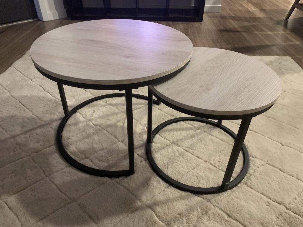
Image of the table purchased from Facebook Marketplace
Now that I have sourced my main base material I started to break apart the smaller table in preparation for mounting it onto the hinge later on. An image of this is below.
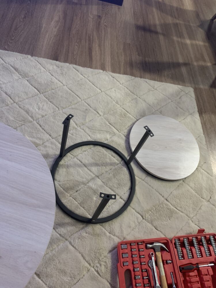
decomposing the bottom tabletop
Now that I got this done I went to go get some hardware from The Home Depot. I purchased a hinge and a corner brace in order to be able to pivot that bottom surface in and out from being under the table.
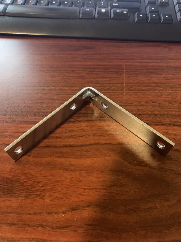
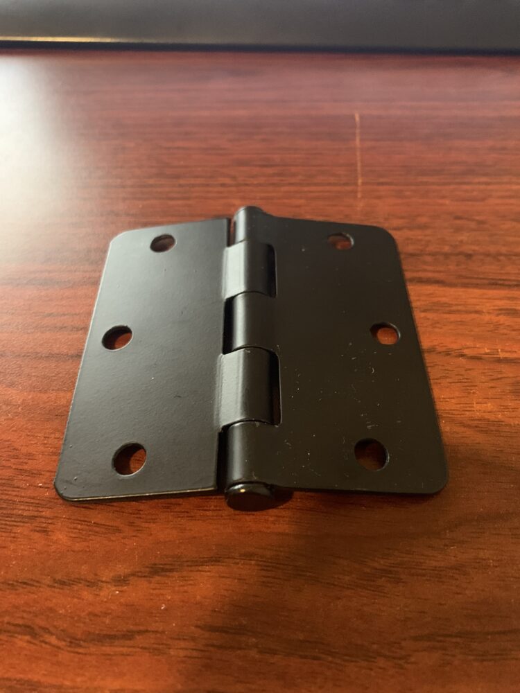
Hardware to make pivot possible
Now that I had my hardware it was time to start to integrate the two tables. This first meant that I needed to put two mounting holes into the base of the main table to mount the hinge. This was completed inside the ITLL workshop where they helped me mark out the distances and utilize a drill press to get the holes exactly centered on the stock. After mounting the hinge successfully utilize the largest fastener possible for the hole width. I then integrated the 90-degree brace into the assembly connecting the little table top onto the hinge. An image of this all together is below.
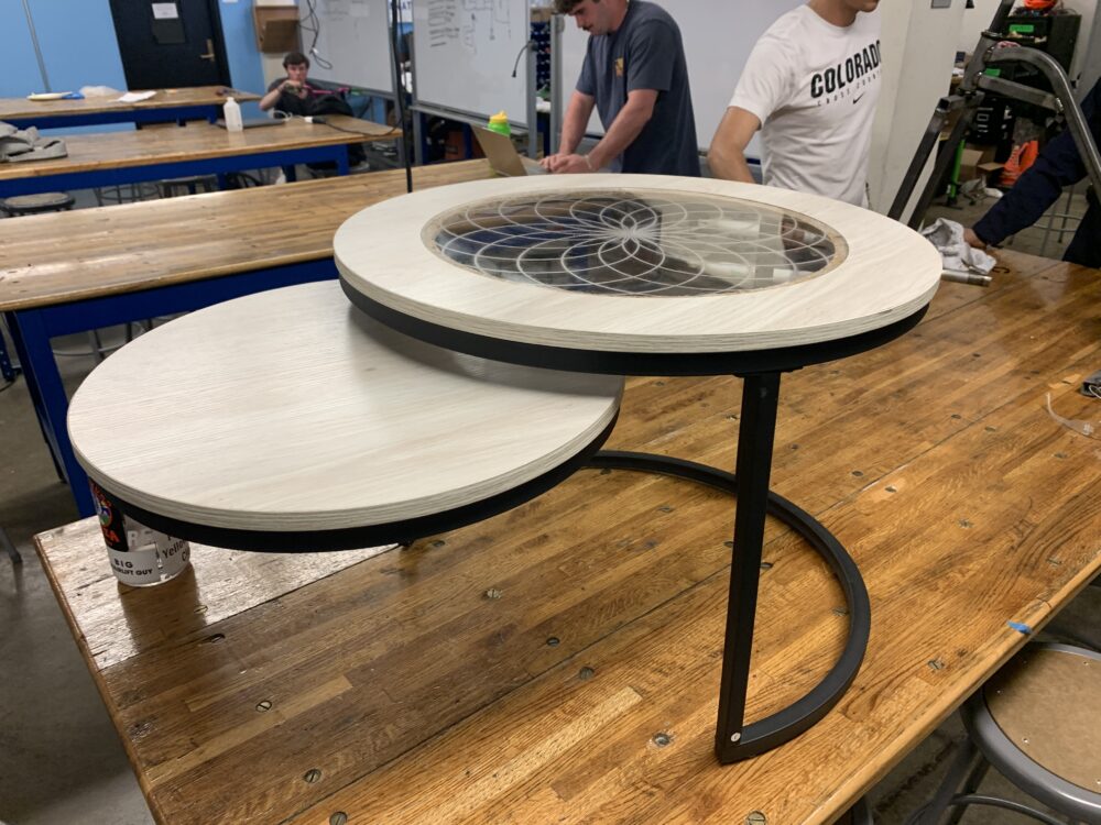
Image of assembly all together for the first time
This was extremely exciting to see everything together and I was super happy with how the aesthetic was coming along. Unfortunately, after I tried to transport this assembly back to my house and continue to work on it the fasteners connecting the corner brace to the hinge sheared when I picked it up. I quickly realized that this was because I tried to use smaller fasteners to connect these two parts. After all, their center-to-center distance of the holes was not the same but I initially believed that I could sneak smaller fasteners in and get away with it. After this setback, I did try to extend one of the holes on the 90-degree brace by making it a slot in the machine shop but due to the location of the angle and the need for extra material to keep the strength of the part this solution did not end up working.
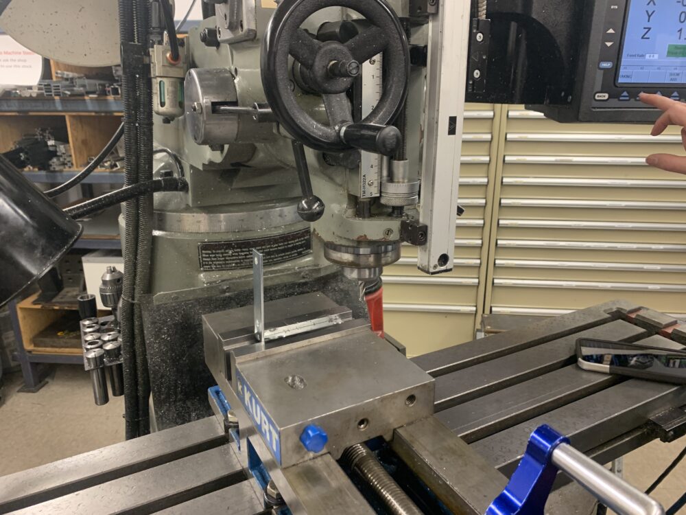
Image of the brace attempting to have its mounting holes extended
After this failure, I decided to go on a trip to McGuckins with two goals in mind:
- Find a new 90-degree base that will interface with the hinge better and allow me to have stronger fasteners
- Make a way to support the load of the extended table better to prevent tipping.
After my McGuckins trip, I ended up collecting solutions to both of these issues! First, I got a new 90-degree hinge that is already slotted and will make it possible to use the maximum width fastener of the hinge which was very important. Second, I found these linear braces that I decided I wanted to use to connect the old circular base of the little table to the assembly to extend the point of pivot of the system while keeping the circular patterning and overall aesthetic of the build. To connect all of this together I used new Stainless Steel fasteners to ensure really sturdy and reliable connections across every part interface. Below are images of both of these solutions in action.
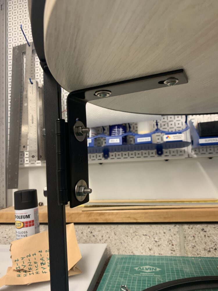
Image of new 90-degree brace in the system highlighting its connection to hinge in the closed position.
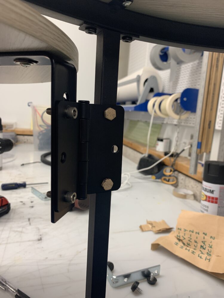
Image of new 90-degree brace in the system highlighting its connection to hinge in the open position.
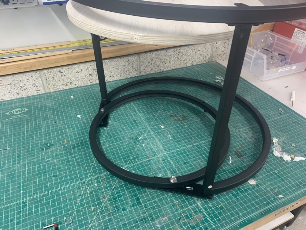
Image of the new base connection that connects the little base to the big base in order to increase stability without taking away from the overall aesthetic of the project.
After these solutions, I was still slightly concerned about the stability of the assembly in use so I tried flipping the small base around to have its overhang to be more exaggerated on the other side as you can see below.
Different orientation of the base assembly to increase even more stability
With this option, I really like how it creates a bit more separation of the two bases and calls a very small hint of interest into it which I feel like the minimalist aesthetic does really well where it barely makes you want to appreciate it but just not too much. This orientation also is a huge improvement for the stability of the assembly so I feel really confident moving forward with it.
The last part of the assembly that I needed to complete was the top table. For the top table, I had to make a hole in the top with a lip, that can hold an acrylic inset, and then paint the entire table top black to match the aesthetic. For the hole, I went to the Idea Forge woodshop and worked with their staff to use a 2 step operation where we used a circular mounted saw to cut the interior hole completely through then came in after with a barring offset drill that was a quarter inch tall (the thickness of the acrylic) to make the inset. Below is an image of this operation’s result.
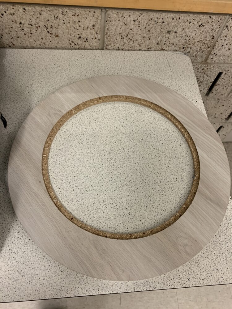
Post machining table top result
After finishing this operation I then went to my acrylic and utilized a laser engraver in the ITLL to create my inset. For the inset, I decided to use a circular repetition pattern in a circular overly that just adds more circularity to the project. Below are images of the during and after of this process.
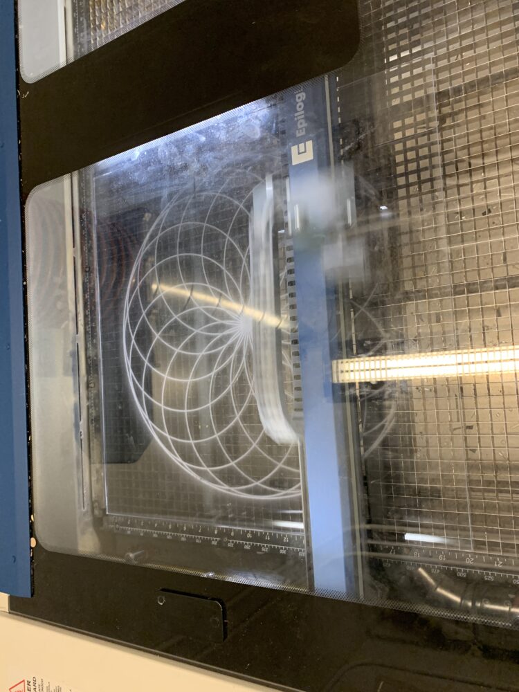
Image of inset being machined on the laser engraver
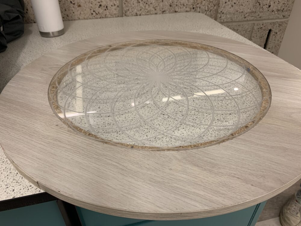
Image of the acrylic inset placed into the table top after the cut
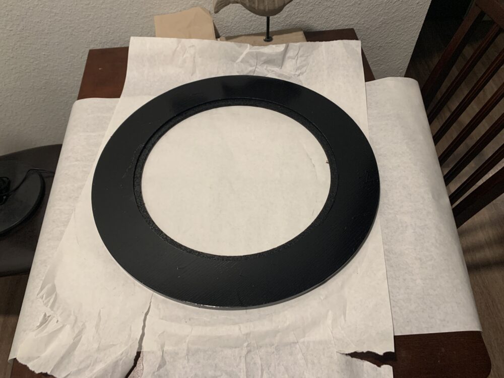
This interface came out really really well and I am really excited about the resulting high-quality fidelity that it created. After having this I was confident to move onto painting the wooden part of this top table in order to hide a bit of the particle board texture that can be seen through the inset. To do this I used a black acrylic spray paint after sanding the entire surface. below are images of the process and the final look!

Image of the in painting process of the surface
The final result of the painting process!
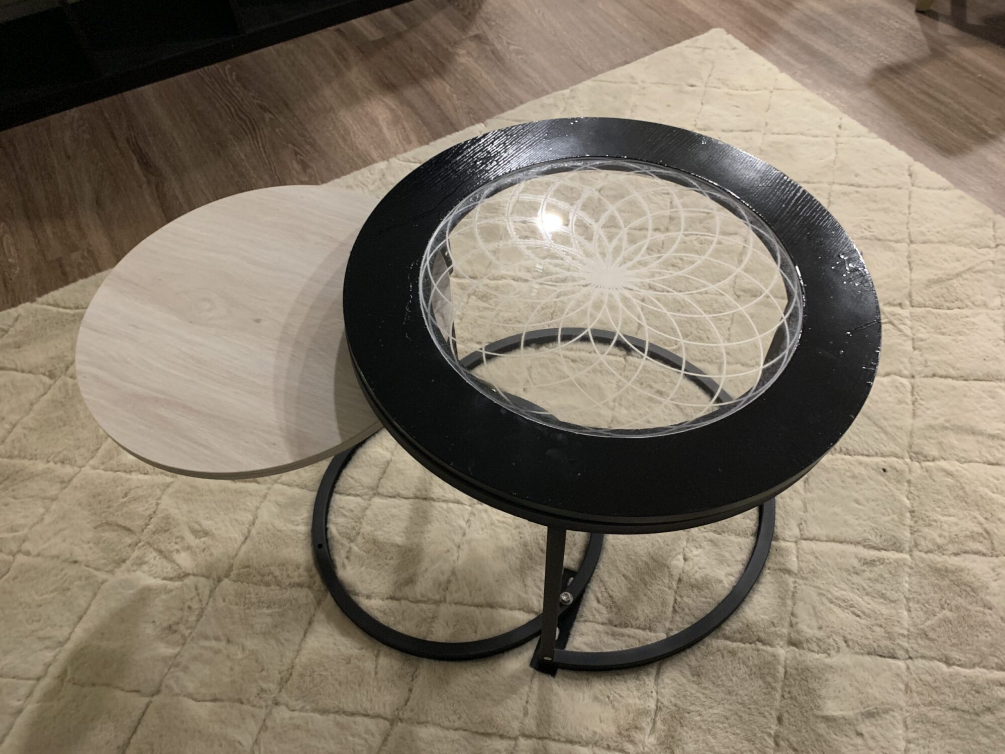
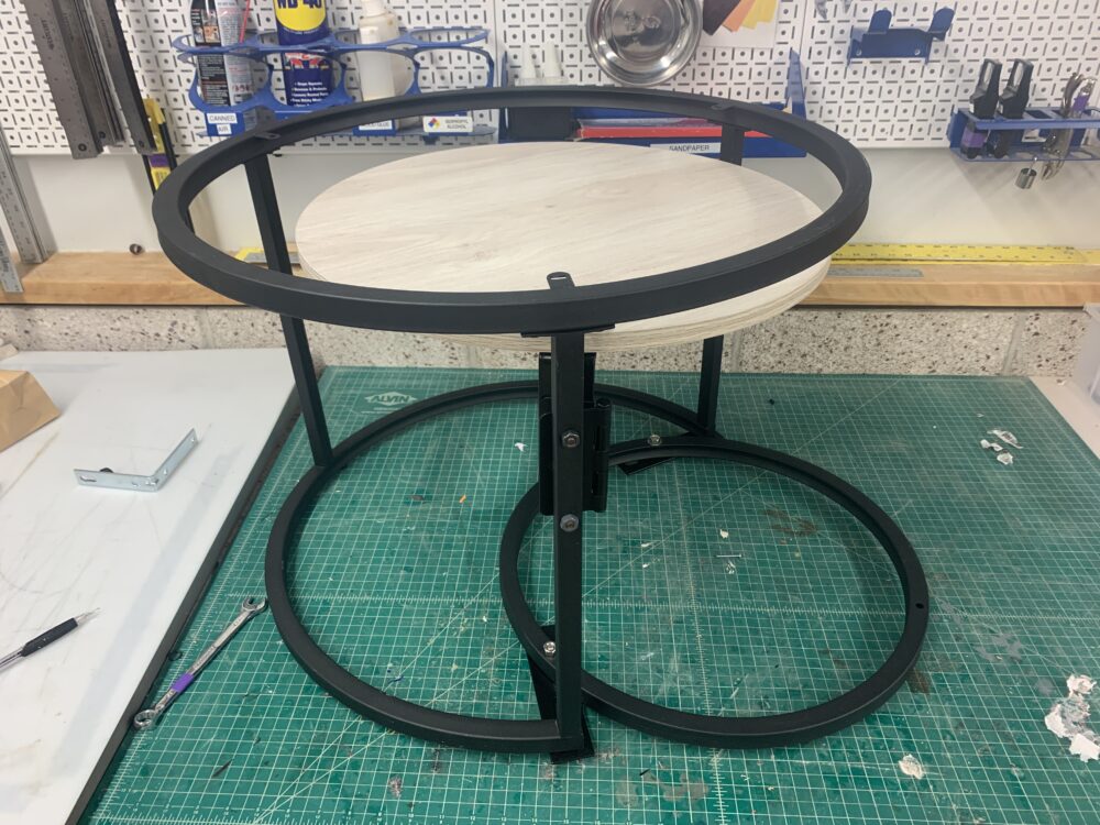
After having the painting finished it was time to put the top back on the assembly and place it into its forever location in my living room as a final product!! Thank you so much for staying along for the process of my project and I hope to see you at Expo to see it in person!
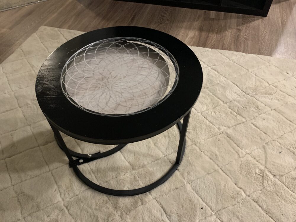
The final product in the closed position

The final product in the open position