
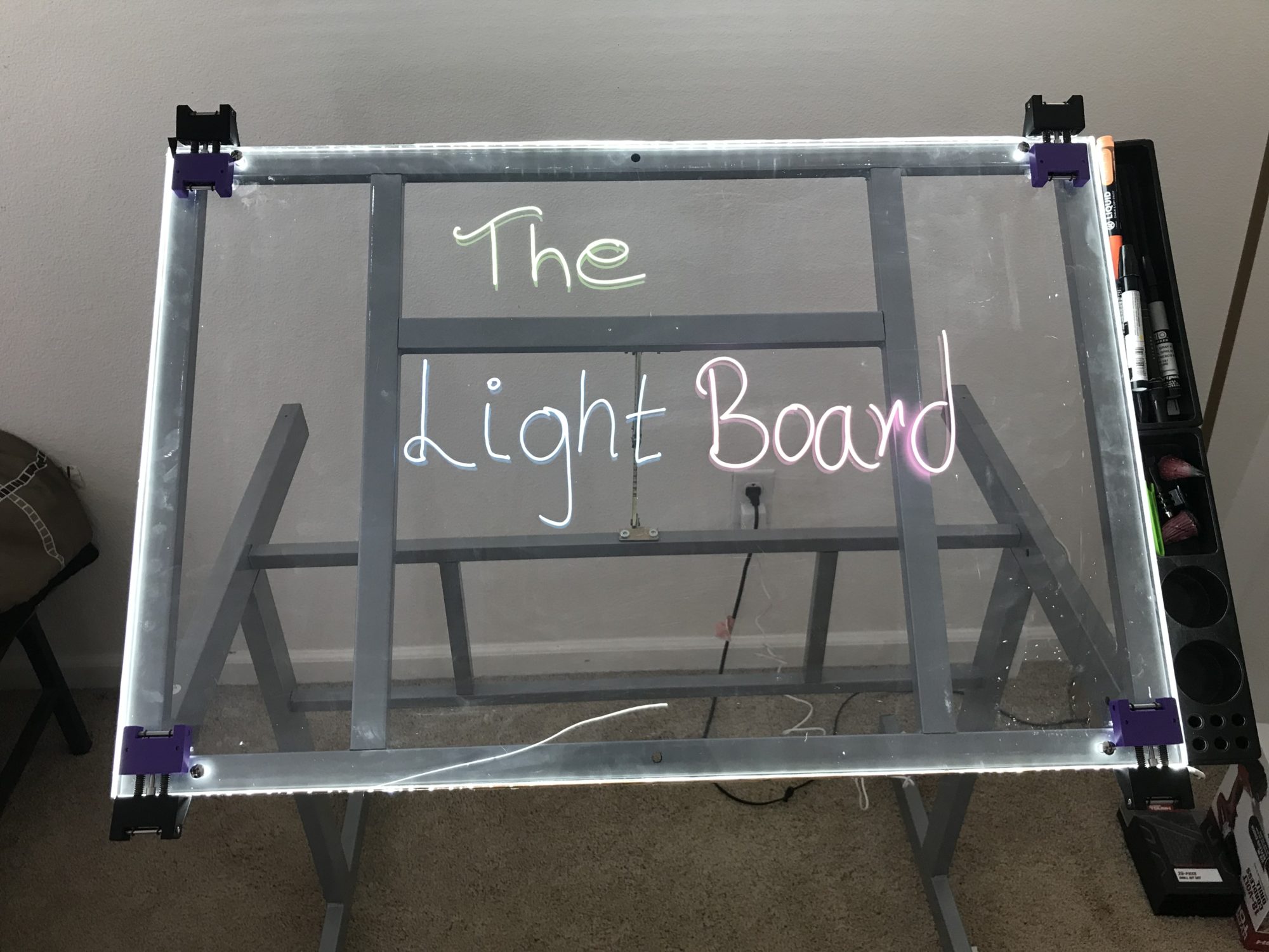
As planned my end product for the final project which is a Lightboard is completely fabricated as of today. The design and fabrication were fun and a little bit challenging but I am happy with how the end product turned out. I utilized the Lulzbot printer for fabricating the LED strip holding fixture at the 4 corners of the board. I ordered other parts required to assemble the holding fixture from McMaster. With reference to my last post, I decided to go with an acrylic sheet instead of Starphire glass because the acrylic sheet is more readily available and post-production machining is easier on acrylic. I ordered the acrylic sheet from Colorado plastics.
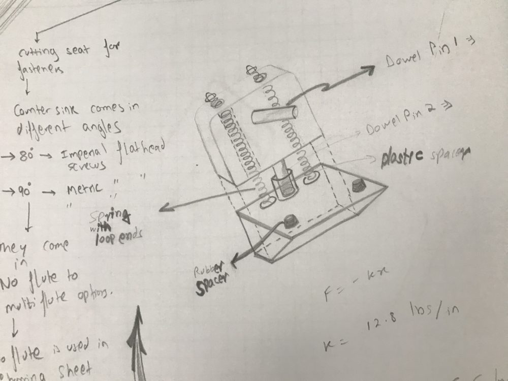
Ideation of holding fixtures: Ideation of the holding fixture was the most interesting part of the project. The holding fixture needed to be two-parter and spring-loaded so that the lower part could press on to the led strip thus keeping it taut at the two ends. Fixing the led strip at the edge could have been done using scotch tape but that would have destroyed the aesthetic of the product and the tape could also come off with a few jerks on the LED strip. Hence I needed a more permanent solution. Something that doesn’t cover the complete length of the edge of the acrylic sheet and looks symmetrical on the product as a whole. Using four holding fixtures at the four corners keeping the LED strip taut at each corner seemed like a better design choice. The progress from the sketch to the final product is shown below.
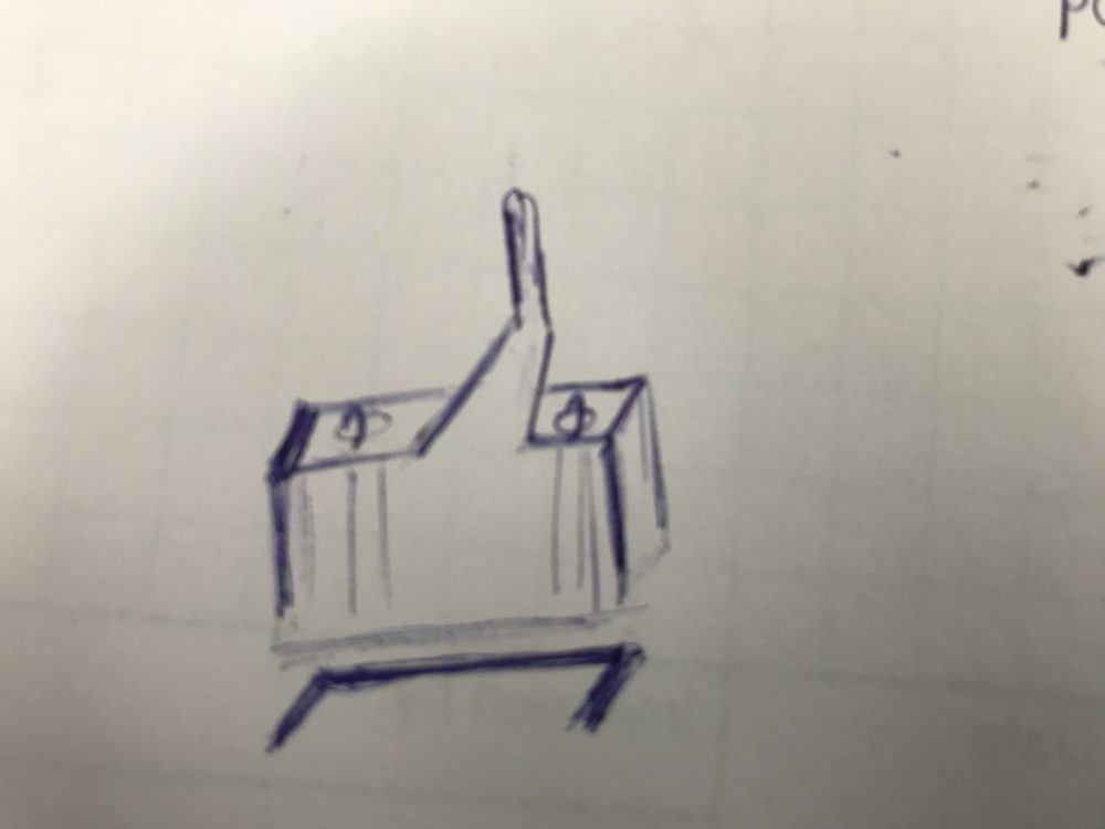
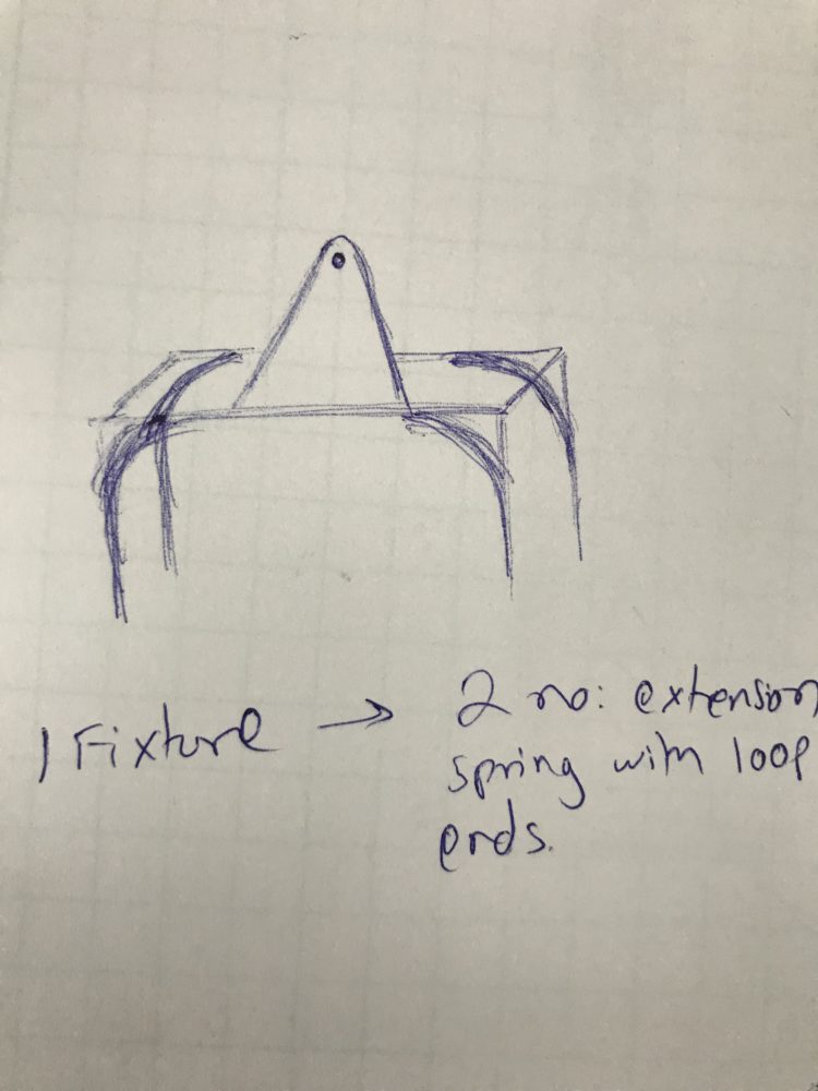
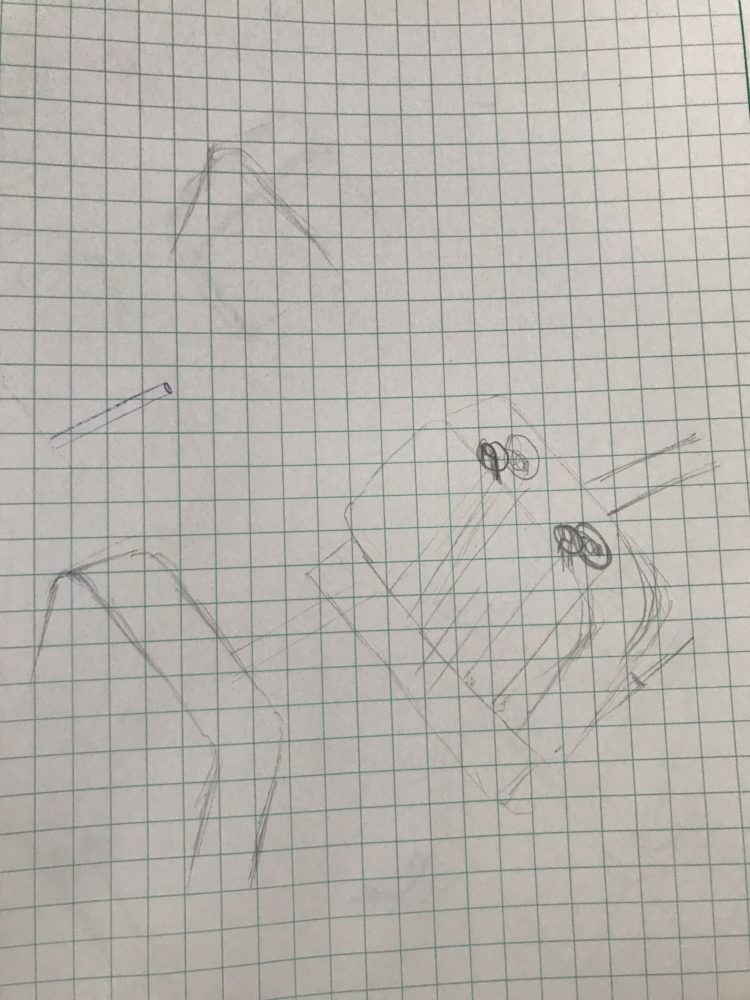
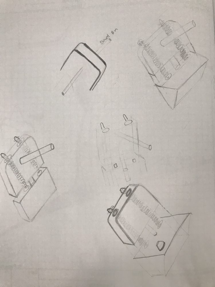
Final Sketch:
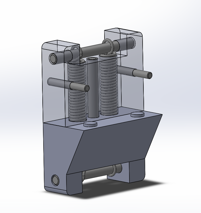
The sketch leads to the CAD model shown below:
The parts needed for the holding fixture were:
- Upper Part- 3D Printed on Lulzbot at ITLL- 4 Nos. -$1.82
- Lower part- 3D Printed on Lulzbot at ITLL- 4 Nos. -$1.82
-
Dowel Pin, 4037 Alloy Steel, 1/8″ Diameter, 1″ Long, 8 Nos.- Ordered from McMaster- $9.12 -
Dowel Pin, 4037 Alloy Steel, 3/16″ Diameter, 2″ Long, 12 Nos.- Ordered from McMaster- $9.39 - Spring with Loop Ends, 2.5″ Long, 0.3″ OD, 0.049″ Wire Diameter,- 12 Nos.- Ordered from McMaster- $26.62
- Aluminum Spacer, 5/16″ OD, 1/4″ Long, – 4 Nos. – Ordered from McMaster- $6.05
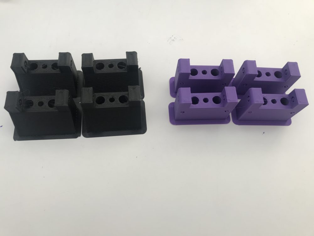
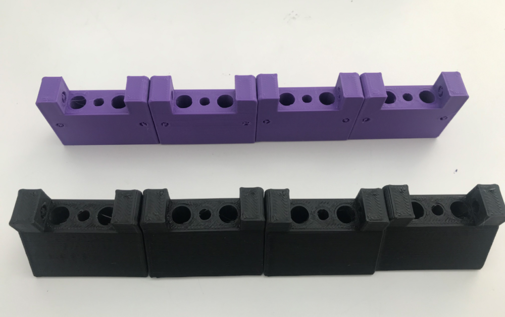
The assembly of the holding fixture was one of the most interesting parts of the project. Before starting the assembly the 3D Printed parts had to be deburred and the flash had to be removed. The pictures of before and after the deburring are shown.
The holding fixture assembly process is shown below in the time-lapse video:
The final assembled holding fixture is shown below:
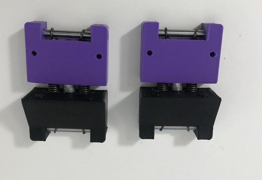
The spring action of the holding fixture is responsible for holding the LED strip taught in place. 15.872 lbs of weight acting on the edge of the board and on the LED strip is keeping the strip intact and taut.
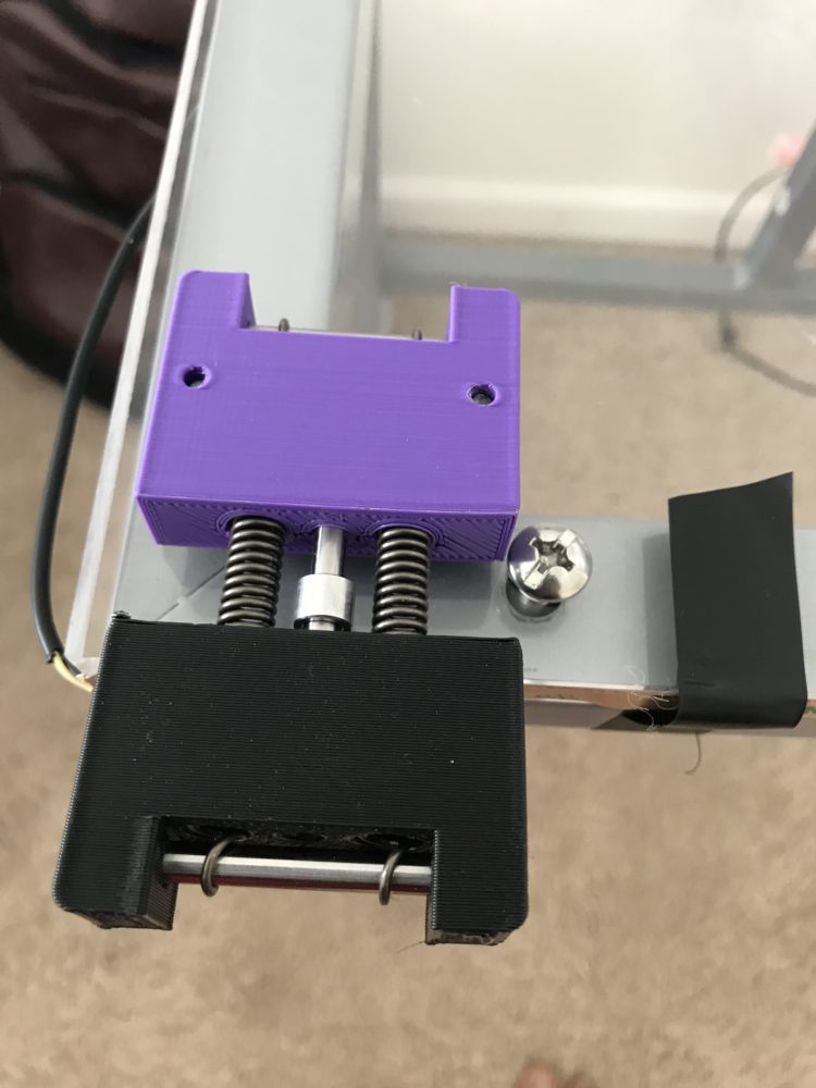
Testing assembly of holding fixture with the acrylic board: The two 1/8″ dowel pins were first press-fitted on the board. They were then inserted in the upper part and the lower part was pulled against the spring force and let force down on the edge of the board and LED strip.
The LED strip was cut into two parts before assembling to the edges. Both parts equal to the long edges of the board. The separated strips were connected with wires on the left edge of the board equal to the smaller edge length. The ends of the wire were soldered to the two stips on the side.
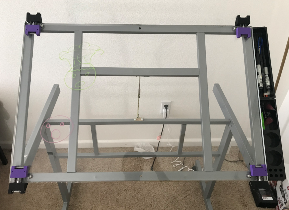
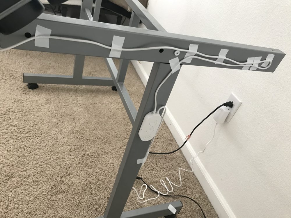
Wire Management: The control switch of the LED strip was attached to the right leg of the drafting table and the wires were guided along with the frame as shown:
Giving the final touches for aesthetic: The smudges were cleaned using 70% IPA and Lint-free paper (Coffee filter). The left edge of the board was taped with white tape which served two purposes. The first was to hold the wire extension that connected the two LED strips and the other was to reflect back escaping light from the edge.
The Final Product:
Cost of the project:
The total cost of the project was around $304 for material and around $40 for tooling. The major cost was for the Acrylic sheet which was $151.88 for the 23.5″x35.5″x0.5″ sheet and $45 for the labour cost of polishing the two long edges of the sheet. The edges were needed to be polished to allow maximum light to reach the centre of the board. The result was of course great.
Problems faced: The major problem faced in this project was a visible scratch on the lower side of the board that was present when the adhesive cover was peeled off the acrylic sheet. I informed Colorado Plastics about it and they offered to make another board for me later. Another minor problem occurred during the assembly of the holding fixture as the calculated spring force was under-estimated for my own strength. This led to a longer assembly time but was handled properly and the final assembly worked great.
Future Possible Changes:
- The major change will be replacing the board when the new one comes from Colorado Plastics.
- A battery-operated and Bluetooth controlled version of the LED strip could be used to make the board more portable in the room.
- Different colour LEDs could be tested to see the effects on the board for change in the aesthetic.
What I intend to do with the product: I intend to use the product for ideation and sketching of new ideas and future projects.
Final Presentation Video:
https://www.youtube.com/watch?v=hz44TWBSQAg
2 Comments. Leave new
Hey Ankit! I love this final project, the marker looks so cool when it is lit up! The clamps are very interesting and impressive, and the solid works model compared to what you ended up with is also impressive! Great work!
This is a great project! I love the lighting and how the markers pop out. It’s really cool to see all the colorful markers you have as well. I am curious as to why you decided to mount it on a desk instead of a traditional board setting! Regardless, it looks fantastic well done!