
Introduction
In this final blog post, I’ll be discussing what my final project was, what I was inspired by, and how I created it. One of my biggest regrets regarding this project is that although I gathered all the materials needed, I was unable to build the final product. This was largely due to the fact that the extruder motor on my 3D printer broke when I was first attempting to prototype parts for my piston design. With that being said, I was able to delve deeper into the design and produce some really cool features that I wouldn’t have had time for if I had been allocating more time for 3D printing and assembly. Additionally, I was able to focus more on creating high-quality renders to showcase some of these awesome features.
The What
As discussed in previous blog posts, for my final project, I wanted to create a lamp. This lamp would have an Edison bulb and a sparkplug switch. This sparkplug switch would not only turn the light on and off but when the light is turned on, there would be a piston assembly that moves in the front of the lamp. Being that I was inspired by the simplicity of two-stroke engine designs, I wanted to have a minimalist aesthetic in this final project. I accomplished this by having mating parts without showing connection points or bearings. The piston assembly, which is the only colorful aspect of this lamp, only shows three moving parts: the piston, connecting rod, and cam (in this case, a flat circle). Since I wasn’t attempting to portray the realistic, complex geometries, I kept the geometries of these parts fairly simple. The GIF below shows an animation of these parts moving when the sparkplug is switched.
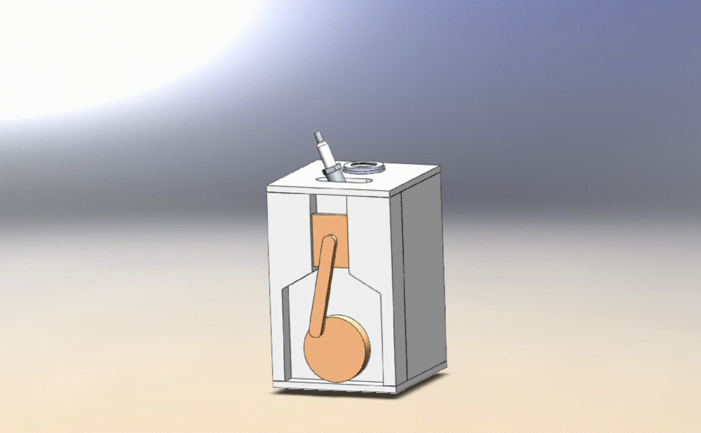
Figure 1: GIF Animation of Piston Moving When Actuated by Sparkplug.
One of my biggest specifications for this project, as I touched on above, was the ability to hide connection points and bearings. I was able to do this by designing the width of the connecting rod to be larger than the diameter of the bearing, plus some extra width to cover up the “relief” features. I designed these relief features to allow for press-fitting the bearings into the moving component. In each of these components, there is a hole for the bearing to go into, which is undersized by 0.001″. Around that hole, there are features to allow for some bending of the material to fit the bearing inside. Similarly, there is a relief feature in each of the shafts that connect the bearing to another moving component. Both of these features are shown below, in an isolated view of the piston, its bearing, and its shaft.
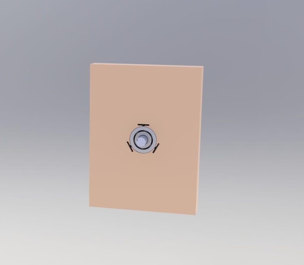
Figure 2: Piston, Bearing, and Shaft.
By having only three moving components, and those components are the only colorful parts, there is minimal complexity and unnecessary parts.
To keep everything (except for bearings) unique for the CAD design, I did not attempt to model the lightbulb, hence why it does not “look” like a lamp as is. This is by design: the lamp socket was modeled according to measured dimensions of the socket I purchased from Home Depot; the same goes for the switch, motor, and sparkplug.
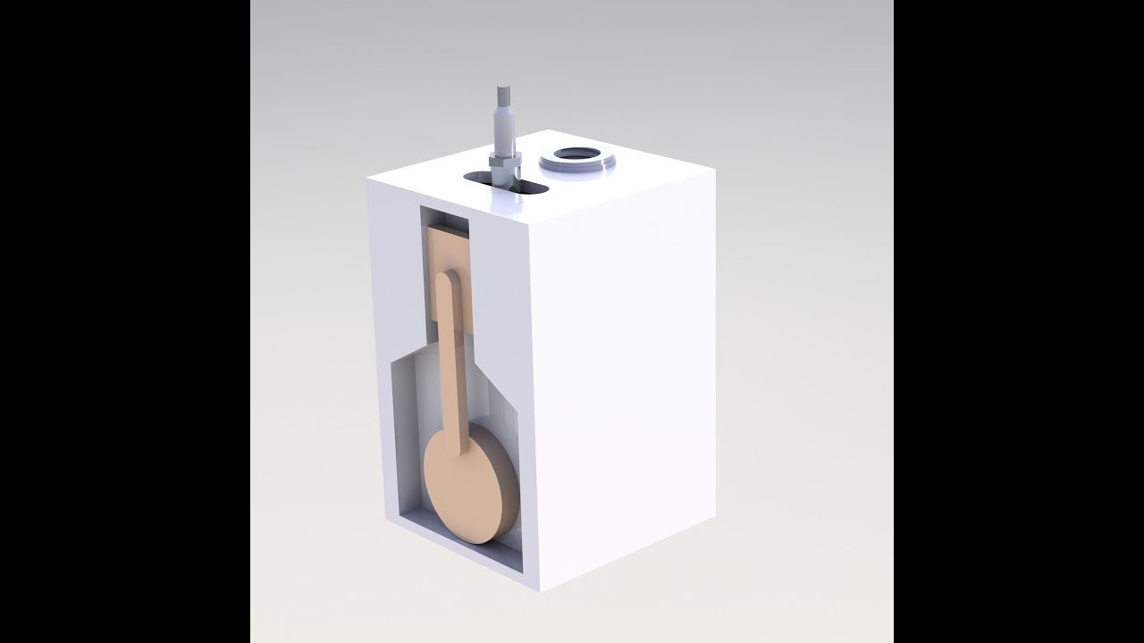
In the section view in Figure 3, you will see how this assembly comes together and what goes into the process.

Figure 3: Section View of Internal Components
Using measurements of the power supply for the motor and the extension cord to power both that and the light bulb socket, I verified that all necessary components will be able to fit within the enclosed volume seen above. To discuss and report back on some of the specifications and constraints I had declared in a previous blog post, I have created a summary below of the successes and failures of those specifications:
Top Five Specifications:
- Volumetric Constraint (4x4x8″): Moderate Failure
- Perhaps this constraint was more of a mistaken estimation, but I slightly exceeded the volume constraint I had listed previously. Currently, the overall volume, including added height for a lightbulb, is 5x5x8″. Thus, my design only slightly exceeds that original specification. I am completely comfortable with a 5×5″ base compared to a 4×4″.
- The piston should not be cylindrical: Success
- This specification was more for the aesthetic cohesiveness of the project. By not having a cylindrical piston, the shapes of the moving objects are less distracting, which is both functional and aesthetic.
- All mating components should not have connections that are visible from a front or top view of the lamp: Success
- All mating components in this project are press-fits. In contrast to the GIF animation in Figure 1, the final product should look more similar to the CAD renderings seen in Figures 2 and 3. I achieved this by oversizing the connecting pin (the same pin used to mate bearings to moving parts) and adding a relief feature to allow for a press-fit.
- Lack of readily visible complex design: Success
- I was able to minimize the number of moving parts seen from a front view of the assembly, which greatly reduces the amount of complexity in this design. In addition to this, the cam that the spark plug goes into in order to flip the switch for the extension cord is also hidden.
- The light and the motor are to be activated by a single switch: Success
- I was able to design a feature that keeps the switch for the extension cord in place, able to be activated by a cam attached to the sparkplug. The cam is attached to the front housing of the assembly and is able to rotate via a bearing. Below is an image that shows a view of the interior interaction between the cam and the switch.
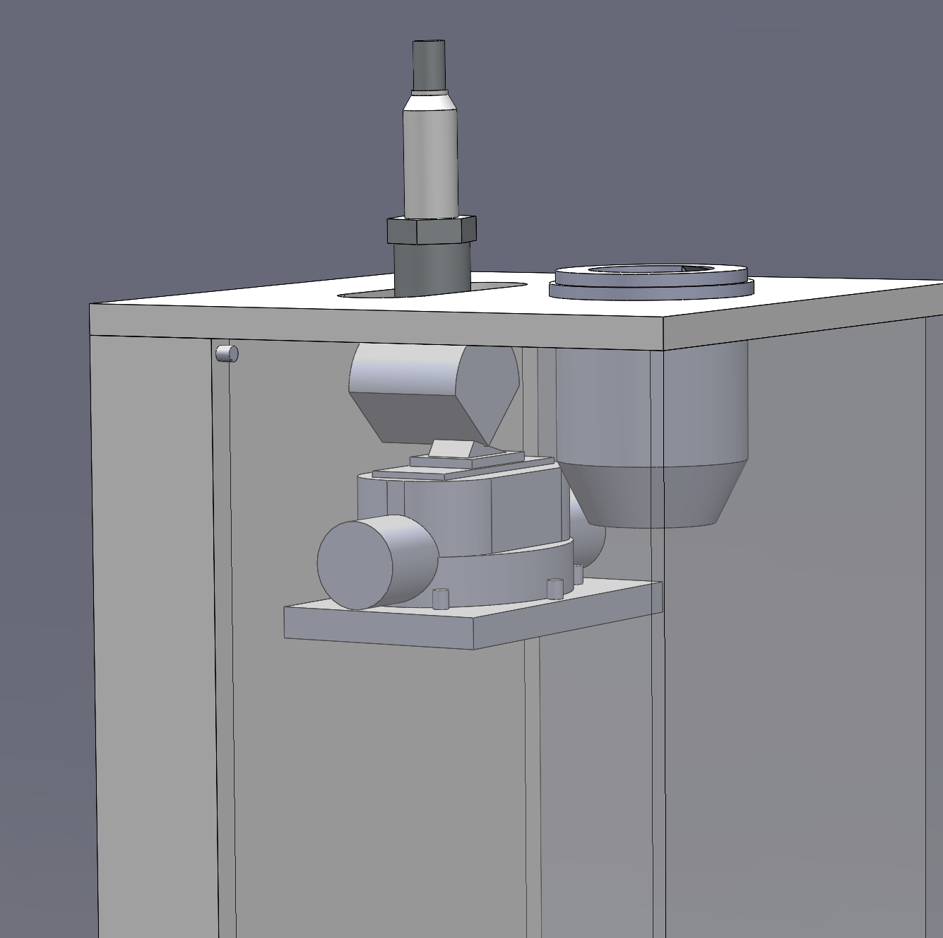
Figure 4: Cam and Switch Interaction.
With those specifications discussed, we can now discuss the constraints:
Top Five Constraints:
- Time: Project to be completed by April 28th: Success*
- I put an asterisk next to success because although I completed the design and testing of electrical features working together, I wasn’t able to actually build the final design. This was disappointing, and even though I set aside a large block of time for 3D printing, I was unable to overcome that, which I am fine with. If I chose to outsource every part to be made, I would have exceeded my cost constraint of $100.
- Electrical Cohesiveness: Success
- As mentioned above, the extension cord was able to power both the light bulb socket and the motor power supply, so this is a success.
- Mobility of Moving Components: Success
- Instead of 3D printing bearings, I decided to use ball bearings from McMaster-Carr, with the exception of one needle bearing used to allow the motor-to-cam interaction. I theorize that this will amount to a less noisy design.
- Modern/Minimalist Aesthetic: Success
- This is probably the constraint that I’m most proud of. It took a significant amount of time to design parts that would not show how they mated together. I also think that even though I did not build my final product, the final renderings do an excellent job of showing how I imagine this would look in real life.
- Cost: Success
- With only having spent just over $40 on materials, I am content with the cost spent. I do wish that it would have been cheaper to manufacture the 3D printed parts via either the idea forge or another vendor, however, I am comfortable saving my money and not exceeding this constraint.
With the what of this project completely covered, I will now discuss how I developed this project.
The How
As stated at the beginning of this report, I did not get the opportunity to build my artifact, but spent a significant amount of time designing, redesigning, simulating, and rendering my project. Below is what my initial plans for a timeline looked like:
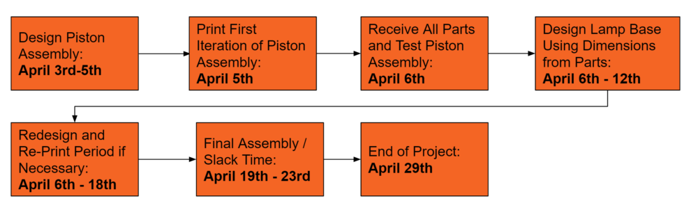
Figure 6: Initial Proposed Schedule
While printing my first iteration of the piston assembly, the extruder motor on my Ender 3 Pro stopped working. I began a print, and the extruder motor would not move at all. After extensive research that lasted about a week, I decided that it would be best for me and the success of my project to decide to put more time into designing the other parts and developing this idea to the point where, if I had a functional printer, I could print all of the parts in a reasonable timeframe. I additionally put hours of thought into how the lamp would assemble. Since this list is extremely long and I do not have the ability to create a video of that assembly, I have attached the assembly directions at the bottom of this post.
Although my project was somewhat derailed by my 3D printer breaking, I was able to still design everything to my specifications and constraints. I was able to put the time that I would’ve taken by 3D printing and iterating and put that towards a more thorough design process. My final schedule is shown below.
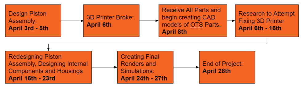
Figure 7: Final Timeline
One of the most difficult sub-assemblies for this design was the spark plug cam assembly to activate the switch for the extension cord. In order to design this, I had to model the switch itself in SolidWorks, design a feature to hold it in place, and then determine how close the cam should be to the switch in order to activate it. Below is an animation of the cam being moved by the sparkplug, showing the interaction between the cam and the switch.
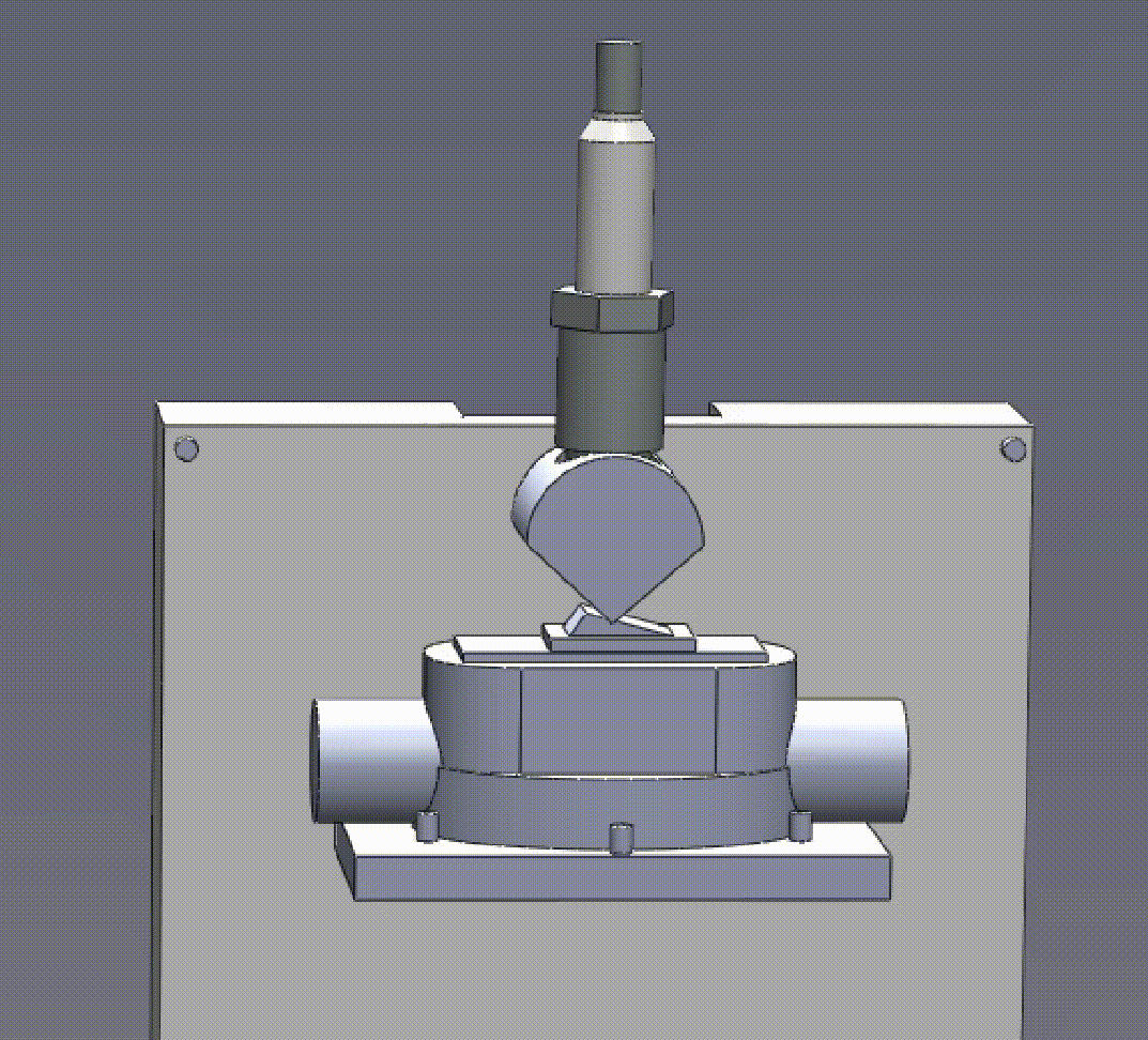
Figure 8: Spark plug cam interacting with the switch.
Additionally, it was difficult to design the motor sub-assembly in a way that would hide the motor and the connecting piece to allow the motor to drive the piston. I ended up using a needle bearing because of the wide inside diameter and relatively closely dimensioned outside diameter.
Functionality aside, I was really excited to see the final renderings of my lamp as I truly believe it achieved the minimalist aesthetic I was going for. I think designing the connections to almost all be press-fits was an excellent idea to make everything merge together. Originally, I was going to have tapped holes to insert M3 screws, followed by placing a cap in each of the counterbored holes to hide the screws.
I then thought, “well what if I don’t use screws at all” and did some research into the sizing of press-fits. I used a textbook that I own, Engineering Drawing and Design, 7th Ed. by Jensen et al, to determine the amount of oversizing to use. This also allows me to have all of the housings machined out of aluminum, metal, or even thick plastic plates, instead of 3D printing. I believe that if I make this in the future, it would be really cool for the housings to be made out of aluminum. Additionally, if I remove the relief features for the bearing inserts, I think the piston assembly could also be made out of metal, Delrin, or another easily machined material.
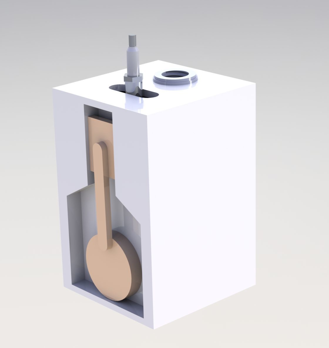
Figure 9: Final CAD Rendering.
Conclusion
This was an extremely fun project to work on, despite the 3D printer issues I had. With my 3D printer breaking, I was able to spend much more time on the design itself, focusing on how to achieve a minimalist aesthetic. I believe this was the most successful aspect of my project as seen in Figure 9. The final rendering is sleek, there are no distracting features or shapes, and the colors are neutral. Additionally, the lamp color would match the color of the piston assembly, which I am happy about. My hope for this project now is to find a manufacturing method to produce these parts and finally assemble what I had worked on for several weeks.
As mentioned in the “how” section of this blog post, I mentioned how I had developed an assembly procedure. This procedure can be found below in Appendix A. Additionally, all images and GIFs in this report have been uniquely designed and developed by myself.
Appendix A: Assembly Instructions:
- Non-Color Specific, Internal Parts:
- Print the adapter between the motor and the cam.
- Print all 24 shaft/pins (0.125″x0.25″).
- Print the spark plug cam.
- Print the motor mount.
- Print the switch holder.
- Orange Filament Parts:
- Print the piston and the cam in the same print.
- Print the connecting rod.
- White Filament Parts:
- Print the front housing.
- Print the top and bottom housings.
- Print the side and back housing.
- Assembly:
- Piston Sub-Assembly:
- Press-fit one bearing and shaft into the piston.
- Press-fit one bearing and shaft into the cam.
- Press-fit two bearings into the connecting arm.
- Press-fit the connecting arm into the shafts coming out of the piston and the cam.
- Front Housing Assembly:
- Press-fit one ball bearing into the 3/8″ hole for the sparkplug cam. Insert shaft for that bearing.
- Press-fit the needle bearing for the motor-cam piece.
- Insert shafts for holding the motor mount and extension cord switch. Attach the switch holder and insert locating pins for holding the switch in place.
- Insert the switch.
- After attaching the cam-to-motor mount to the motor, insert this part into the needle bearing. Follow by attaching the motor mount to the front housing.
- Glue the cam-to-motor mount to the specified location on the cam. Place piston within the slider area on the front of the front housing.
- Insert 4 pins to connect the side and back housing.
- Housings and Sparkplug-Cam:
- Insert all pins as necessary.
- Place front housing on top of bottom housing and press-fit the two housings together. The assembly should be free-standing at this point.
- Insert the sparkplug cam into the ball bearing at the inside of the front housing, such that the cam interacts with the switch.
- Plugin the motor power supply to the extension cord outlet. Place light bulb socket into the top housing and then plug the socket extension into the extension cord outlet.
- Press-fit the side and back housing into the front housing.
- Place top housing on top of the lamp and press-fit into the specified holes.
- Final Touches:
- Insert spark plug through the slot to go into the spark plug cam.
- Insert the light bulb into the socket.
- Power on by flipping the spark plug.
- Piston Sub-Assembly:
2 Comments. Leave new
This is a really cool project! It’s a bummer that your 3D printer stopped working right when you needed it, but you did a really nice job of digitally designing the lamp. It’s also great that you were able to think about some of the more detailed design elements that you may not have dug into had you just built the physical thing from the start. The minimalistic aesthetic looks really nice, but it would be cool to be able to see more of the internal moving components as well. I also really like your choice of lightbulb – it plays well with the industrial vibe. Will you make a physical artifact when your 3D printer is fixed? Nice work!
Yes, absolutely!